EP0333690B1 - Vorrichtung für Hängebühne - Google Patents
Vorrichtung für Hängebühne Download PDFInfo
- Publication number
- EP0333690B1 EP0333690B1 EP89850089A EP89850089A EP0333690B1 EP 0333690 B1 EP0333690 B1 EP 0333690B1 EP 89850089 A EP89850089 A EP 89850089A EP 89850089 A EP89850089 A EP 89850089A EP 0333690 B1 EP0333690 B1 EP 0333690B1
- Authority
- EP
- European Patent Office
- Prior art keywords
- post
- cradle
- platform
- arrangement according
- attachment
- Prior art date
- Legal status (The legal status is an assumption and is not a legal conclusion. Google has not performed a legal analysis and makes no representation as to the accuracy of the status listed.)
- Expired - Lifetime
Links
- 230000005484 gravity Effects 0.000 claims description 7
- XAGFODPZIPBFFR-UHFFFAOYSA-N aluminium Chemical compound [Al] XAGFODPZIPBFFR-UHFFFAOYSA-N 0.000 claims description 4
- 229910052782 aluminium Inorganic materials 0.000 claims description 4
- 239000004411 aluminium Substances 0.000 claims description 4
- 230000003213 activating effect Effects 0.000 claims 1
- 238000006073 displacement reaction Methods 0.000 description 3
- 238000010276 construction Methods 0.000 description 2
- 230000002093 peripheral effect Effects 0.000 description 2
- 230000000087 stabilizing effect Effects 0.000 description 2
- 238000009825 accumulation Methods 0.000 description 1
- 230000004913 activation Effects 0.000 description 1
- 230000003247 decreasing effect Effects 0.000 description 1
- 230000000694 effects Effects 0.000 description 1
- 238000012986 modification Methods 0.000 description 1
- 230000004048 modification Effects 0.000 description 1
Images
Classifications
-
- E—FIXED CONSTRUCTIONS
- E04—BUILDING
- E04G—SCAFFOLDING; FORMS; SHUTTERING; BUILDING IMPLEMENTS OR AIDS, OR THEIR USE; HANDLING BUILDING MATERIALS ON THE SITE; REPAIRING, BREAKING-UP OR OTHER WORK ON EXISTING BUILDINGS
- E04G3/00—Scaffolds essentially supported by building constructions, e.g. adjustable in height
- E04G3/28—Mobile scaffolds; Scaffolds with mobile platforms
- E04G3/30—Mobile scaffolds; Scaffolds with mobile platforms suspended by flexible supporting elements, e.g. cables
Definitions
- Hanging cradles of this kind are often used for working on the external wall surfaces of building structures, and when the cradle is used for this purpose the uppermost part of the line is attached to a holder located adjacent to the roof of the building and the cradle can be raised and lowered along the line, with the aid of a machine intended herefor.
- This shifting of the gravitational centre will take place, for instance, when a person carried by the cradle moves along the platform, from the central region of the cradle to the end or edge regions thereof.
- a qualified technical problem resides in the ability to construct a hanging cradle in a manner such that the ability of the cradle to tilt in response to a lateral shift in the gravitational centre can be reduced with the aid of a long post or arm, which extends vertically upwards from the cradle platform, while providing conditions which will enable a person standing on the platform, with the cradle raised to its upper limit, to carry out work in the immediate vicinity of the attachment point and in certain instances also to work in areas located above the attachment point, and in addition to be able to take stabilizing measures.
- the post or arm shall be of simple design and operates in conjunction with simple journal means, and shall be held torsionally rigid adjacent to the platform while affording the desired vertical return movement of the post relative to the platform.
- a technical problem resides in providing conditions which will enable the post to co-act readily with a spring device so constructed and arranged as to normally hold the post in an upper extended position, and capable of being compressed by an externally applied force so as to displace the post axially downwards, this axial lowering of the post taking place when the upper free part of the post abuts the upper, first attachment and the lifting force is allowed to act on the platform to raise the same, so that the post will again take an upper position when the force ceases with the post being held torsionally rigid to the platform during the whole of this movement.
- Another technical problem in the present context is one of providing simple means for achieving this technical effect while simultaneously creating conditions such that the post will be flexurally rigid and assist in stabilizing the tendency of the cradle to swing or tilt laterally when the gravitational centre shifts.
- a further technical problem is one of providing a hanging cradle which provides the facility of a long flexurally rigid post and therewith a more stable cradle at high working heights, while still enabling work to be carried out adjacent to and above the attachment point when standing solely on the platform.
- a further technical problem resides in the provision of a post or arm which has the form of a straight tube, preferably an aluminium tube, of uniform thickness and which as able to solve the aforesaid problem by being arranged for axial displacement in at least two journals, and also for co-action with one or more simple spring device, which urge the tube against a stop, and with which arrangement the length of tube above the platform can be decreased by downward displacement of the tube, and the cross-sectional shape of the tube is adapted for torsionally rigid connection of the post to the platform.
- the present invention thus relates to an arrangement in lifting cradles of the kind which comprise a platform and a post extending vertically from the platform, as stated in the preamble of claim 1.
- a hanging cradle of this kind is provided with means as stated in the characterizing part of claim 1.
- the advantages primarily afforded by an arrangement constructed in accordance with the invention reside in the possibility of using a rod or tube of uniform thickness, preferably an aluminium tube, so that the upwardly extending post can be given a considerable length and therewith reduce the tilting tendencies of the hanging cradle when the centre of gravity shifts.
- a further advantage is afforded by the fact that the inventive arrangement enables a person, carried by and standing on the working platform of the cradle, to carry out work adjacent to the attachment located above the cradle and even above said attachment, by allowing the rod to run axially through fixed journal devices.
- the invention also affords the advantage of an upper horizontal projection by means of which the line can be located within the central region of the working platform, and therewith requiring a rod cross-section which will enable the rod to be connected to the platform so as to be held torsionally rigid.
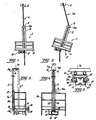
- the present invention relates to an arrangement in hanging cradles, and particularly, but not exclusively, to an arrangement in a hanging cradle 1 which comprises a normally horizontal platform surface 2 and an arm or post 3 which extends upwardly from the platform, said cradle being constructed to work with and hang from a single line 4.
- the platform 2, or support surface forms the bottom of a cradle basket, equipped with a handrail or like safety guard.
- the guide 6 is located on the upper free part 3a of the post 3 and a second attachment 7 is located beneath the platform 2 and therewith also beneath the guide 6.
- the cradle 1 is raised and lowered along the line 4 with the aid of a known device 8, which is effective in changing the length of line 4a extending between the guide 6 and the first attachment 5, the device in this case having the form of a machine (8) which drives the line and which can be switched to rotate in one direction or the other by switch means not shown.
- the machine may be an electrical machine.
- Figure 1 illustrates the attitude taken by the cradle 1 when its centre of gravity acts in the direction of the line 4.
- the present invention overcomes this drawback, by enabling the distance "H” ( Figure 3) between the platform 2 and the attachment 6 at the upper free part 3a of the post 3 to be reduced when the upper free part 3a of said post is in co-action with the first attachment 5, when normal measures are taken to raise the cradle further. This is effected by causing the machine 8 to raise the platform 2 further.
- the post has the form of a rod or tube of uniform thickness.
- the post may have any desired cross-sectional shape, although the illustrated post has the outer cross-sectional shape shown in Figure 5.
- the post 3 is journalled in two journal devices or journals 11 and 12, of which one device 11 is rigidly attached to the uppermost part of the handrail or like guard 1a and the other device is mounted on the lowermost part of the guard.
- the post 3 has on its lowermost part a small projection 3b which will prevent the post from being moved axially upwards to an extent greater than that illustrated in Figure 3. The post 3 can still be moved downwards, however.
- Each of the spring devices consists of a tension spring of known configuration.
- the journals 11 and 12 are mutally identical, and it will be seen from Figure 4 that the device 11 is attached to the guard or handrail 1a at 11a.
- the line 4 is a double-line comprising line runs 4a, 4b each of which co-acts with a respective line pulley 15, 16.
- a single line as used in the present specification does not necessarily mean a line which consists of a single run, but also a line arrangement in which two or more line runs are arranged closely adjacent to one another.
- the cross-sectional shape of the post 3 is illustrated in Figure 5.
- the post of this embodiment is essentially of rectangular cross-section and consists of an extended aluminium profile.
- This profile has two mutually opposing runner surfaces 17, 18 and the distance between the runners is only insignificantly greater than the diameter of a ball bearing 19 mounted on a U-shaped rail 20 in a known manner.
- the rail 20 is attached to the guard or handrail in a known manner.
- the profile also has a further runner surface 21 against which the peripheral surface of a ball bearing (not shown) located beneath the ball bearing 19 will run.
- the profile also presents runner surfaces 17', 18' for a ball bearing 19' and a further runner surface 21' for co-action with the peripheral surface for a further ball bearing (not shown).
- the journal device identified generally by 11 in Figure 5 is identical with the journal 12.
- This arrangement of four bearings in the journal device 11 and four bearings in the journal device 12 will enable the post 3 attached to the cradle to be held torsionally rigid, while still permitting the post to move up and down in the direction of its longitudinal axis.
- the post 3 is arranged externally of a guard 1a forming part of the cradle basket, whereas the guide 6 is located on the extremity of a horizontal projection 10, which extends in over the guard and terminates at a point which corresponds or substantially corresponds to the location of the centre of gravity of the cradle when unloaded.
- the cradle platform 2 may also have arranged on outer surfaces thereof, on either side of the line 4, support wheels which are intended to lie against the surface of the structure to be worked on with the aid of the cradle. This surface is indicated in Figure 3 and is referenced 16, and one wheel 17 is also shown in this Figure.
Landscapes
- Engineering & Computer Science (AREA)
- Architecture (AREA)
- Mechanical Engineering (AREA)
- Civil Engineering (AREA)
- Structural Engineering (AREA)
- Jib Cranes (AREA)
- Load-Engaging Elements For Cranes (AREA)
Claims (10)
- Hängegerüstanordnung (1) einer Art, die folgendes umfaßt: eine Arbeitsbühne (2), eine von der Arbeitsbühne nach oben verlaufende Säule (3), die mit der Arbeitsbühne (2) drehsteif zusammenwirkt und zur Arbeit mit einem Seil (4), einer ersten Befestigung oder Riemenscheibe (5), die mit dem Seil (4), einer am freien oberen Teil der Säule (3) angebrachten Führung oder Riemenscheibe (6) zusammenwirkt , ausgelegt ist, normalerweise eine unter der ersten Befestigung (5) und der Führung (6) angebrachte zweite Befestigung (7) sowie Mittel (8) zum Heben und Senken des Gerüsts durch Änderung des Abstands zwischen der Führung (6) und der ersten Befestigung (5) mittels einer Betätigungsmaschine (8) für das Seil (4), dadurch gekennzeichnet, daß der Abstand zwischen der Bühne (2) und dem oberen freien Teil (3a) der Säule verringert werden kann, wenn der obere freie Teil (3a) mit der ersten Befestigung (5) zusammenwirkt, und daß Mittel (8) für ein weiteres Heben des Gerüsts vorgesehen sind.
- Anordnung nach Anspruch 1, dadurch gekennzeichnet, daß die Säule (3) in Gestalt eines Stabs vorliegt, der zur Ausführung axialer Bewegung in mindestens zwei Zapfen (11, 12) angebracht ist, die in bezug auf die Arbeitsbühne (2) feststehen.
- Anordnung nach Anspruch 2, dadurch gekennzeichnet, daß der Stab (3) röhrenförmig ist und vorzugsweise aus Aluminium besteht.
- Anordnung nach Anspruch 1, 2 oder 3, dadurch gekennzeichnet, daß eine Federvorrichtung (13, 14) zwischen der Säule und der Bühne oder einem anderen starren Teil angebracht ist, die die Säule (3) in einer von der Bühne (2) weggerichteten Stellung hält und dann zusammengedrückt wird, wenn die Säule (3) von einer von außen aufgebrachten Kraft dazu gezwungen wird, sich axial nach unten zu bewegen, wobei die Säule (3) in ihren nach oben verlaufenden Zustand zurückkehrt, wenn die Kraft entfernt wird.
- Anordnung nach Anspruch 1 oder 2, gekennzeichnet durch ein elastisches Element, das mit dem Stab derart zusammenwirkt, daß der Stab in einer oberen Stellung gehalten wird.
- Anordnung nach Anspruch 2, dadurch gekennzeichnet, daß mindestens einer der Zapfen (11, 12) einen Aufbau umfaßt, der eine Mehrzahl von Rollenlagern oder Kugellagern beinhaltet, die gegen den Stab (3) laufen.
- Anordnung nach Anspruch 6, dadurch gekennzeichnet, daß eines der Lager oben neben zwei Lagern angeordnet ist.
- Anordnung nach Anspruch 1, dadurch gekennzeichnet, daß die zweite Befestigung (7) einen unterhalb der Bühne (2) befestigten Antriebsmotor umfaßt, der mit einem Rad oder mehreren Rädern verbunden ist, die das Seil (4) derart betätigen, daß das Gerüst (1) je nach Drehrichtung entweder gehoben oder gesenkt wird.
- Anordnung nach Anspruch 1, dadurch gekennzeichnet, daß die Säule neben einer Sicherheitsvorrichtung oder Haltestange am Gerüst angebracht ist, während sich die Führung am äußeren Ende eines Vorsprungs befindet, der über die Sicherheitsvorrichtung hineinsteht und an einem Punkt endet, der mit der Schwerpunktlinie des Gerüsts zusammenfällt oder im wesentlichen mit ihr zusammenfällt, wenn keine Last auf es wirkt.
- Anordnung nach Anspruch 4, dadurch gekennzeichnet, daß die Anordnung auf beiden Seiten des Stabs jeweils eine Federvorrichtung aufweist.
Priority Applications (1)
| Application Number | Priority Date | Filing Date | Title |
|---|---|---|---|
| AT89850089T ATE92567T1 (de) | 1988-03-17 | 1989-03-16 | Vorrichtung fuer haengebuehne. |
Applications Claiming Priority (4)
| Application Number | Priority Date | Filing Date | Title |
|---|---|---|---|
| SE8800976 | 1988-03-17 | ||
| SE8800976A SE464983B (sv) | 1988-03-17 | 1988-03-17 | Anordning vid haengstaellning |
| SE8804217 | 1988-11-22 | ||
| SE8804217A SE467164B (sv) | 1988-11-22 | 1988-11-22 | Anordning vid haengstaellning |
Publications (3)
| Publication Number | Publication Date |
|---|---|
| EP0333690A2 EP0333690A2 (de) | 1989-09-20 |
| EP0333690A3 EP0333690A3 (en) | 1990-05-16 |
| EP0333690B1 true EP0333690B1 (de) | 1993-08-04 |
Family
ID=26660139
Family Applications (1)
| Application Number | Title | Priority Date | Filing Date |
|---|---|---|---|
| EP89850089A Expired - Lifetime EP0333690B1 (de) | 1988-03-17 | 1989-03-16 | Vorrichtung für Hängebühne |
Country Status (3)
| Country | Link |
|---|---|
| US (1) | US4987971A (de) |
| EP (1) | EP0333690B1 (de) |
| DE (1) | DE68907962D1 (de) |
Families Citing this family (3)
| Publication number | Priority date | Publication date | Assignee | Title |
|---|---|---|---|---|
| GB9422573D0 (en) * | 1994-11-09 | 1995-01-04 | E M & I Safety Systems Ltd | An access platform |
| GB0208601D0 (en) * | 2002-04-15 | 2002-05-22 | E M & I Maritime Ltd | A mobile access system and method |
| US11247886B2 (en) * | 2018-01-11 | 2022-02-15 | Fritel & Associates, L.L.C. | Personnel basket for overhead cranes |
Family Cites Families (11)
| Publication number | Priority date | Publication date | Assignee | Title |
|---|---|---|---|---|
| US2662734A (en) * | 1952-06-13 | 1953-12-15 | Wilberd F Feigenbaum | Swing stage scaffold |
| FR1174851A (fr) * | 1957-05-09 | 1959-03-17 | Siège sellette ascenseur pour travaux sur parois verticales | |
| FR1236286A (fr) * | 1958-09-18 | 1960-07-15 | Spider Staging Inc | Treuil |
| US2998094A (en) * | 1958-09-18 | 1961-08-29 | Spider Staging Inc | Level winding winch mechanism |
| US3464520A (en) * | 1967-11-14 | 1969-09-02 | Leonard A Anderson | Self-operated elevator |
| US3630315A (en) * | 1970-09-08 | 1971-12-28 | Robert A Meyer | Seat scaffold |
| CA975405A (en) * | 1973-03-30 | 1975-09-30 | Arthur J. Leduc | Hoist basket |
| US3967696A (en) * | 1974-07-08 | 1976-07-06 | Donald James Nix | Stage safety stabilizer |
| US4225012A (en) * | 1979-04-06 | 1980-09-30 | International Telephone And Telegraph Corporation | Safety clamp device and apparatus utilizing same |
| US4650036A (en) * | 1985-05-09 | 1987-03-17 | Masako Matsuda | Emergency evacuation apparatus |
| US4602698A (en) * | 1985-05-13 | 1986-07-29 | Grant Walter R | Hunting chair |
-
1989
- 1989-03-16 EP EP89850089A patent/EP0333690B1/de not_active Expired - Lifetime
- 1989-03-16 DE DE8989850089T patent/DE68907962D1/de not_active Expired - Lifetime
- 1989-03-17 US US07/324,655 patent/US4987971A/en not_active Expired - Fee Related
Also Published As
| Publication number | Publication date |
|---|---|
| DE68907962D1 (de) | 1993-09-09 |
| EP0333690A3 (en) | 1990-05-16 |
| EP0333690A2 (de) | 1989-09-20 |
| US4987971A (en) | 1991-01-29 |
Similar Documents
| Publication | Publication Date | Title |
|---|---|---|
| JP6154921B1 (ja) | 風力発電装置におけるブレードのメンテナンス用ゴンドラ装置 | |
| KR20010050406A (ko) | 직선붐 공중작업 플랫폼용 수축가능한 평형추 | |
| EP0333690B1 (de) | Vorrichtung für Hängebühne | |
| CN210127623U (zh) | 一种建筑工程施工用的拉升吊篮 | |
| EP3296251B1 (de) | Höhenzugängliche arbeitsbühne mit horizontal verschiebbarem korb | |
| US3447635A (en) | Elevating platform | |
| CN216428973U (zh) | 一种道路桥隧施工用移动平台 | |
| EP0267888B1 (de) | Hebevorrichtung für Patienten | |
| KR102554166B1 (ko) | 코너용 곤돌라 | |
| CN216336353U (zh) | 一种建筑施工用提升装置 | |
| CN117703050A (zh) | 一种伸缩式造楼设备支撑装置及顶升方法 | |
| JPH0737319B2 (ja) | ゴンドラ懸吊装置 | |
| KR100274505B1 (ko) | 유리 워싱장치 | |
| JP2805588B2 (ja) | 作業用ゴンドラ | |
| CN221242748U (zh) | 一种清洁设备的移动机构 | |
| CN115215252B (zh) | 升降装置和起重机 | |
| CN223738962U (zh) | 一种建筑施工用悬吊防护装置 | |
| CN210947678U (zh) | 一种用铝板钎焊的高空作业吊篮 | |
| CN213477601U (zh) | 装配式建筑可移动外挂施工平台 | |
| KR102890013B1 (ko) | 와이어를 이용한 안전 리프트 | |
| CN217759885U (zh) | 一种采光顶钢结构焊接用软平台搭建装置 | |
| CN219469520U (zh) | 一种建筑施工用物料吊装设备 | |
| CN220504483U (zh) | 一种液压升降脚手架套架导向组件 | |
| CN215047846U (zh) | 一种用于房屋建筑施工的安全升降装置 | |
| KR200186535Y1 (ko) | 비닐하우스의 작업바구니 보조 승강장치 |
Legal Events
| Date | Code | Title | Description |
|---|---|---|---|
| PUAI | Public reference made under article 153(3) epc to a published international application that has entered the european phase |
Free format text: ORIGINAL CODE: 0009012 |
|
| AK | Designated contracting states |
Kind code of ref document: A2 Designated state(s): AT BE CH DE ES FR GB GR IT LI LU NL SE |
|
| PUAL | Search report despatched |
Free format text: ORIGINAL CODE: 0009013 |
|
| AK | Designated contracting states |
Kind code of ref document: A3 Designated state(s): AT BE CH DE ES FR GB GR IT LI LU NL SE |
|
| 17P | Request for examination filed |
Effective date: 19900914 |
|
| 17Q | First examination report despatched |
Effective date: 19910508 |
|
| GRAA | (expected) grant |
Free format text: ORIGINAL CODE: 0009210 |
|
| AK | Designated contracting states |
Kind code of ref document: B1 Designated state(s): AT BE CH DE ES FR GB GR IT LI LU NL SE |
|
| PG25 | Lapsed in a contracting state [announced via postgrant information from national office to epo] |
Ref country code: IT Free format text: LAPSE BECAUSE OF FAILURE TO SUBMIT A TRANSLATION OF THE DESCRIPTION OR TO PAY THE FEE WITHIN THE PRESCRIBED TIME-LIMIT;WARNING: LAPSES OF ITALIAN PATENTS WITH EFFECTIVE DATE BEFORE 2007 MAY HAVE OCCURRED AT ANY TIME BEFORE 2007. THE CORRECT EFFECTIVE DATE MAY BE DIFFERENT FROM THE ONE RECORDED. Effective date: 19930804 Ref country code: CH Effective date: 19930804 Ref country code: GR Free format text: LAPSE BECAUSE OF FAILURE TO SUBMIT A TRANSLATION OF THE DESCRIPTION OR TO PAY THE FEE WITHIN THE PRESCRIBED TIME-LIMIT Effective date: 19930804 Ref country code: NL Effective date: 19930804 Ref country code: SE Effective date: 19930804 Ref country code: AT Effective date: 19930804 Ref country code: FR Effective date: 19930804 Ref country code: ES Free format text: THE PATENT HAS BEEN ANNULLED BY A DECISION OF A NATIONAL AUTHORITY Effective date: 19930804 Ref country code: LI Effective date: 19930804 Ref country code: BE Effective date: 19930804 Ref country code: DE Effective date: 19930804 |
|
| REF | Corresponds to: |
Ref document number: 92567 Country of ref document: AT Date of ref document: 19930815 Kind code of ref document: T |
|
| REF | Corresponds to: |
Ref document number: 68907962 Country of ref document: DE Date of ref document: 19930909 |
|
| REG | Reference to a national code |
Ref country code: CH Ref legal event code: PL |
|
| EN | Fr: translation not filed | ||
| NLV1 | Nl: lapsed or annulled due to failure to fulfill the requirements of art. 29p and 29m of the patents act | ||
| PG25 | Lapsed in a contracting state [announced via postgrant information from national office to epo] |
Ref country code: GB Effective date: 19940316 |
|
| PG25 | Lapsed in a contracting state [announced via postgrant information from national office to epo] |
Ref country code: LU Free format text: LAPSE BECAUSE OF NON-PAYMENT OF DUE FEES Effective date: 19940331 |
|
| PLBE | No opposition filed within time limit |
Free format text: ORIGINAL CODE: 0009261 |
|
| STAA | Information on the status of an ep patent application or granted ep patent |
Free format text: STATUS: NO OPPOSITION FILED WITHIN TIME LIMIT |
|
| 26N | No opposition filed | ||
| GBPC | Gb: european patent ceased through non-payment of renewal fee |
Effective date: 19940316 |