EP0334227A1 - Schnellwechselvorrichtung für drehende Werkzeuge oder Messer - Google Patents
Schnellwechselvorrichtung für drehende Werkzeuge oder Messer Download PDFInfo
- Publication number
- EP0334227A1 EP0334227A1 EP89104784A EP89104784A EP0334227A1 EP 0334227 A1 EP0334227 A1 EP 0334227A1 EP 89104784 A EP89104784 A EP 89104784A EP 89104784 A EP89104784 A EP 89104784A EP 0334227 A1 EP0334227 A1 EP 0334227A1
- Authority
- EP
- European Patent Office
- Prior art keywords
- tool
- retaining element
- blade
- annular retaining
- recess
- Prior art date
- Legal status (The legal status is an assumption and is not a legal conclusion. Google has not performed a legal analysis and makes no representation as to the accuracy of the status listed.)
- Granted
Links
- 238000006073 displacement reaction Methods 0.000 claims description 3
- 238000010276 construction Methods 0.000 description 5
- 238000005520 cutting process Methods 0.000 description 3
- 210000002445 nipple Anatomy 0.000 description 3
- 208000031968 Cadaver Diseases 0.000 description 1
- 230000006835 compression Effects 0.000 description 1
- 238000007906 compression Methods 0.000 description 1
- 230000008878 coupling Effects 0.000 description 1
- 238000010168 coupling process Methods 0.000 description 1
- 238000005859 coupling reaction Methods 0.000 description 1
Images


Classifications
-
- B—PERFORMING OPERATIONS; TRANSPORTING
- B23—MACHINE TOOLS; METAL-WORKING NOT OTHERWISE PROVIDED FOR
- B23D—PLANING; SLOTTING; SHEARING; BROACHING; SAWING; FILING; SCRAPING; LIKE OPERATIONS FOR WORKING METAL BY REMOVING MATERIAL, NOT OTHERWISE PROVIDED FOR
- B23D35/00—Tools for shearing machines or shearing devices; Holders or chucks for shearing tools
- B23D35/008—Means for changing the cutting members
-
- B—PERFORMING OPERATIONS; TRANSPORTING
- B26—HAND CUTTING TOOLS; CUTTING; SEVERING
- B26D—CUTTING; DETAILS COMMON TO MACHINES FOR PERFORATING, PUNCHING, CUTTING-OUT, STAMPING-OUT OR SEVERING
- B26D7/00—Details of apparatus for cutting, cutting-out, stamping-out, punching, perforating, or severing by means other than cutting
- B26D7/26—Means for mounting or adjusting the cutting member; Means for adjusting the stroke of the cutting member
- B26D7/2614—Means for mounting the cutting member
-
- B—PERFORMING OPERATIONS; TRANSPORTING
- B26—HAND CUTTING TOOLS; CUTTING; SEVERING
- B26D—CUTTING; DETAILS COMMON TO MACHINES FOR PERFORATING, PUNCHING, CUTTING-OUT, STAMPING-OUT OR SEVERING
- B26D7/00—Details of apparatus for cutting, cutting-out, stamping-out, punching, perforating, or severing by means other than cutting
- B26D7/26—Means for mounting or adjusting the cutting member; Means for adjusting the stroke of the cutting member
- B26D7/2628—Means for adjusting the position of the cutting member
- B26D7/2642—Means for adjusting the position of the cutting member for slotting cutters
-
- Y—GENERAL TAGGING OF NEW TECHNOLOGICAL DEVELOPMENTS; GENERAL TAGGING OF CROSS-SECTIONAL TECHNOLOGIES SPANNING OVER SEVERAL SECTIONS OF THE IPC; TECHNICAL SUBJECTS COVERED BY FORMER USPC CROSS-REFERENCE ART COLLECTIONS [XRACs] AND DIGESTS
- Y10—TECHNICAL SUBJECTS COVERED BY FORMER USPC
- Y10T—TECHNICAL SUBJECTS COVERED BY FORMER US CLASSIFICATION
- Y10T83/00—Cutting
- Y10T83/465—Cutting motion of tool has component in direction of moving work
- Y10T83/4766—Orbital motion of cutting blade
- Y10T83/4795—Rotary tool
- Y10T83/4798—Segmented disc slitting or slotting tool
-
- Y—GENERAL TAGGING OF NEW TECHNOLOGICAL DEVELOPMENTS; GENERAL TAGGING OF CROSS-SECTIONAL TECHNOLOGIES SPANNING OVER SEVERAL SECTIONS OF THE IPC; TECHNICAL SUBJECTS COVERED BY FORMER USPC CROSS-REFERENCE ART COLLECTIONS [XRACs] AND DIGESTS
- Y10—TECHNICAL SUBJECTS COVERED BY FORMER USPC
- Y10T—TECHNICAL SUBJECTS COVERED BY FORMER US CLASSIFICATION
- Y10T83/00—Cutting
- Y10T83/929—Tool or tool with support
- Y10T83/9372—Rotatable type
- Y10T83/9377—Mounting of tool about rod-type shaft
-
- Y—GENERAL TAGGING OF NEW TECHNOLOGICAL DEVELOPMENTS; GENERAL TAGGING OF CROSS-SECTIONAL TECHNOLOGIES SPANNING OVER SEVERAL SECTIONS OF THE IPC; TECHNICAL SUBJECTS COVERED BY FORMER USPC CROSS-REFERENCE ART COLLECTIONS [XRACs] AND DIGESTS
- Y10—TECHNICAL SUBJECTS COVERED BY FORMER USPC
- Y10T—TECHNICAL SUBJECTS COVERED BY FORMER US CLASSIFICATION
- Y10T83/00—Cutting
- Y10T83/929—Tool or tool with support
- Y10T83/9372—Rotatable type
- Y10T83/9403—Disc type
-
- Y—GENERAL TAGGING OF NEW TECHNOLOGICAL DEVELOPMENTS; GENERAL TAGGING OF CROSS-SECTIONAL TECHNOLOGIES SPANNING OVER SEVERAL SECTIONS OF THE IPC; TECHNICAL SUBJECTS COVERED BY FORMER USPC CROSS-REFERENCE ART COLLECTIONS [XRACs] AND DIGESTS
- Y10—TECHNICAL SUBJECTS COVERED BY FORMER USPC
- Y10T—TECHNICAL SUBJECTS COVERED BY FORMER US CLASSIFICATION
- Y10T83/00—Cutting
- Y10T83/929—Tool or tool with support
- Y10T83/9457—Joint or connection
- Y10T83/9464—For rotary tool
- Y10T83/9469—Adjustable
Definitions
- the present invention relates to a device for rapidly mounting and dismounting tools or blades on a circular device supported by a rotary shaft, several of said tools or blades being spaced circumferentially in the same plane between two parallel annular retaining elements.
- the tools for example cutting tools have the shape of an annular sector and can be generally designated as blades. They cooperate with a counter-tool placed on a shaft parallel to the shaft carrying the circular devices for, for example, cutting slots in a plate material passing between the tools and the counter-tools. These cutting operations are carried out by means of several circular devices spaced laterally on their shaft so as to carry out simultaneous cuts at several places of the sheet material.
- two diametrically opposed tools fixed on a circular device, it is possible to make two cuts by each turn of the shaft, for example a cut at the front and rear edges of the plate material to follow the variation in format of the cuts.
- each pinion engages in the teeth of each inner gear ring and will cause, on command, the rotation thereof.
- a main object of the present invention is therefore to provide a solution allowing the rapid assembly and disassembly of tools or blades carried by a circular device using a simple, efficient and economical construction.
- the invention provides a device for the rapid assembly and disassembly of tools or blades on at least one circular device supported by a rotating shaft, several said tools or blades being spaced circumferentially in the same plane between two parallel annular retaining elements, characterized in that the two annular retaining elements are mounted on the rotary shaft, the second annular retaining element being arranged so that it can be angularly displaced relative to the first annular retaining element, the second retaining element having at least one recess arranged on its circumference and extending radially inwards, said recess having a circumferential opening corresponding to the length of a tool or blade, in that the first annular retaining element has on one of its faces a plurality of bores distributed circumferentially over a first constant radius and intended to receive pins fixed on one of the lateral faces of the tool or blade, in that said first annular retaining element is equipped with an internal toothed crown having on one of s faces a plurality of bores distributed
- the device has the advantage that the assembly and disassembly of the tools or blades does not require any fixing by means of screws. Fixing by means of nipples to be simply inserted into the retaining elements is much faster and can be done without tools.
- the tools are thus enclosed between the two annular retaining elements.
- the attachment of the tools by means of pins can be done for fixed tools and for mobile tools adjustable circumferentially relative to the fixed tools.
- the nipples of these are engaged in the bores carried by the face of the first annular retaining element while, in the case of mobile tools, the nipples of these are engaged in the bores arranged in the face of the crown internal gear.
- the hub 2 of a first annular retaining element 3 is fixedly mounted, using keys, on a rotary shaft.
- a second annular retaining element 4, cooperating with the first, is mounted on the hub 2 and can be turned relative to the first annular retaining element 3 by being guided between two rings 5 and 6 mounted on the hub 2.
- the element retaining ring 3 has a concentric housing 7 relative to the axis of the rotary shaft 1 in which is housed an inner toothed crown 8.
- the concentric housing 7 of the annular retaining element 3 is machined so that the front face of the inner ring gear 8 and the front face of the flange 9 of the annular retaining element 3 are in a common plane 10.
- the internal toothed crown 8 can be driven by means of a pinion not shown so as to vary the circumferential position of the movable tool 14 relative to the stationary tool 15.
- the rotary shaft 1 generally carries several apparatus of the same construction arranged side by side along of the rotary shaft 1.
- a control shaft (not shown) carries a corresponding number of pinions, one per circular device, so as to ensure the simultaneous drive of the internal toothed crowns 8, thus allowing adjustment. e simultaneous of all mobile tools.
- the second annular retaining element 4 has on its inner face a circular groove 18.
- This circular groove 18 is intended to receive either the stud 13 or the stud 16 depending on whether a stationary tool or a mobile tool is used, it is to say that the tool 15 is pivoted or not on itself.
- the two annular retaining elements 3 and 4 can be angularly displaced relative to each other, this due to the fact that the pins 13 or 16, depending on whether the "fixed tool” or “tool” version is used mobile ", will lodge in the circular groove 18.
- FIG. 3 shows the mounting of a movable tool 15 whose pins 13 are introduced into the bores 11 of the inner ring gear 8 while the pins 16 will come, after rotation of the annular retaining element 4 to freely engage in the groove circular 18.
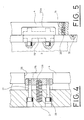
- the annular retaining element 4 With the movable tool 15 in place opposite the recess 25, the annular retaining element 4 will be angularly moved until the recess 25 is in front of a locking body 26 which will engage in said recess 25 and thereby block the annular retaining element 4 relative to the other annular retaining element 3 while ensuring the lateral position of the tool 15, the faces of which will then be in contact with the inner faces of each of said annular retaining elements 3 and 4.
- the locking body 26, the same length as the recess 25, is mounted on the retaining element annular 3 by means of two partially threaded screws 27 screwed into the locking body 26.
- a compression spring 28 is placed between the locking body 26 and the annular retaining element 3.
- the locking body 26 can be pushed in the direction axial inwards, against the action of the spring 28, to release it from the recess 25.
- the locking body 26 is guided by the partially threaded screws 27, the non-threaded part of which moves in bores 29 arranged in the annular retaining element 3.
- Fig. 5 shows a variant of the device.
- the recess in the annular retaining element 4 crosses the latter only partially and has the form of a housing 25a open on the inner face of said annular retaining element 4.
- a tool 14 or 15 can be inserted radially into this housing 25a.
- the annular retaining element 4 is then angularly displaced so that the housing 25a is no longer in front of the tool 15, thus ensuring the lateral position of the latter.
Landscapes
- Engineering & Computer Science (AREA)
- Mechanical Engineering (AREA)
- Life Sciences & Earth Sciences (AREA)
- Forests & Forestry (AREA)
- Nonmetal Cutting Devices (AREA)
- Details Of Cutting Devices (AREA)
- Clamps And Clips (AREA)
- Gripping On Spindles (AREA)
- Food-Manufacturing Devices (AREA)
- Snaps, Bayonet Connections, Set Pins, And Snap Rings (AREA)
- Drilling Tools (AREA)
- Cutting Tools, Boring Holders, And Turrets (AREA)
- Shearing Machines (AREA)
Priority Applications (1)
| Application Number | Priority Date | Filing Date | Title |
|---|---|---|---|
| AT89104784T ATE75989T1 (de) | 1988-03-22 | 1989-03-17 | Schnellwechselvorrichtung fuer drehende werkzeuge oder messer. |
Applications Claiming Priority (2)
| Application Number | Priority Date | Filing Date | Title |
|---|---|---|---|
| FR8804053A FR2628999B1 (fr) | 1988-03-22 | 1988-03-22 | Dispositif pour le montage et le demontage rapide d'outils ou de lames circulaires sur un porte-outil en forme d'arbre |
| FR8804053 | 1988-03-22 |
Publications (2)
| Publication Number | Publication Date |
|---|---|
| EP0334227A1 true EP0334227A1 (de) | 1989-09-27 |
| EP0334227B1 EP0334227B1 (de) | 1992-05-13 |
Family
ID=9364704
Family Applications (1)
| Application Number | Title | Priority Date | Filing Date |
|---|---|---|---|
| EP89104784A Expired - Lifetime EP0334227B1 (de) | 1988-03-22 | 1989-03-17 | Schnellwechselvorrichtung für drehende Werkzeuge oder Messer |
Country Status (8)
| Country | Link |
|---|---|
| US (1) | US4932298A (de) |
| EP (1) | EP0334227B1 (de) |
| JP (1) | JPH0716913B2 (de) |
| AT (1) | ATE75989T1 (de) |
| CA (1) | CA1320041C (de) |
| DE (1) | DE68901480D1 (de) |
| ES (1) | ES2030929T3 (de) |
| FR (1) | FR2628999B1 (de) |
Families Citing this family (9)
| Publication number | Priority date | Publication date | Assignee | Title |
|---|---|---|---|---|
| US5074180A (en) * | 1989-08-18 | 1991-12-24 | Ringspann Gmbh | Clamping system for clamping a cutter roller in axially shiftable position on a shaft |
| US5144874A (en) * | 1991-05-20 | 1992-09-08 | Garrett Jimmy R | Rotary cutter knife |
| IT1281203B1 (it) * | 1995-02-09 | 1998-02-17 | Sasib Spa | Dispositivo per l'esecuzione di tagli in direzione di avanzamento di pezzi di materiale sottile. |
| US5890410A (en) * | 1997-03-19 | 1999-04-06 | Hinojosa; Domingo | Holding assembly for cutting blade |
| US6165543A (en) * | 1998-06-17 | 2000-12-26 | Nec Corporation | Method of making organic EL device and organic EL transfer base plate |
| CH694087A5 (fr) * | 2000-03-30 | 2004-07-15 | Bobst Sa | Dispositif pour rompre de points d'attache reliant deux bords d'une ligne de coupe. |
| CN101163577B (zh) * | 2005-02-25 | 2011-01-19 | 尼克拉斯·彼得森 | 切割压痕轮组件,及对可压缩材料进行切割压痕的方法 |
| SE540174C2 (en) * | 2015-11-25 | 2018-04-24 | Berg Ind Ab | Arrangement for cutting paper board sheets, and machine comprising said arrangement |
| CN112549158A (zh) * | 2020-11-06 | 2021-03-26 | 龙南骏亚精密电路有限公司 | 一种用于电路板钻孔主轴的快速安装机构 |
Citations (3)
| Publication number | Priority date | Publication date | Assignee | Title |
|---|---|---|---|---|
| CH414076A (de) * | 1964-05-20 | 1966-05-31 | Havelco S A | Scheibenschneidmaschine |
| FR2104112A5 (de) * | 1970-08-12 | 1972-04-14 | Simon Ltd Henry | |
| US3985066A (en) * | 1975-05-15 | 1976-10-12 | S&S Corrugated Paper Machinery Co., Inc. | Single point means for slotter adjustment |
Family Cites Families (4)
| Publication number | Priority date | Publication date | Assignee | Title |
|---|---|---|---|---|
| US4003300A (en) * | 1974-09-11 | 1977-01-18 | Molins Machine Company, Inc. | Apparatus having dual slotter shafts |
| US3952637A (en) * | 1975-04-14 | 1976-04-27 | Koppers Company, Inc. | Apparatus for changing the rotary position of a slotter member and for changing the relative position between fixed and movable knives on the slotter member |
| US4502357A (en) * | 1983-07-07 | 1985-03-05 | Hussissian Vahan A | Slotting head |
| JPS62159958A (ja) * | 1986-01-09 | 1987-07-15 | Tamura Electric Works Ltd | 留守番電話装置 |
-
1988
- 1988-03-22 FR FR8804053A patent/FR2628999B1/fr not_active Expired - Fee Related
-
1989
- 1989-03-17 DE DE8989104784T patent/DE68901480D1/de not_active Expired - Lifetime
- 1989-03-17 EP EP89104784A patent/EP0334227B1/de not_active Expired - Lifetime
- 1989-03-17 ES ES198989104784T patent/ES2030929T3/es not_active Expired - Lifetime
- 1989-03-17 AT AT89104784T patent/ATE75989T1/de not_active IP Right Cessation
- 1989-03-21 CA CA000594298A patent/CA1320041C/en not_active Expired - Fee Related
- 1989-03-22 JP JP1070292A patent/JPH0716913B2/ja not_active Expired - Fee Related
- 1989-03-22 US US07/326,999 patent/US4932298A/en not_active Expired - Lifetime
Patent Citations (3)
| Publication number | Priority date | Publication date | Assignee | Title |
|---|---|---|---|---|
| CH414076A (de) * | 1964-05-20 | 1966-05-31 | Havelco S A | Scheibenschneidmaschine |
| FR2104112A5 (de) * | 1970-08-12 | 1972-04-14 | Simon Ltd Henry | |
| US3985066A (en) * | 1975-05-15 | 1976-10-12 | S&S Corrugated Paper Machinery Co., Inc. | Single point means for slotter adjustment |
Also Published As
| Publication number | Publication date |
|---|---|
| FR2628999A1 (fr) | 1989-09-29 |
| EP0334227B1 (de) | 1992-05-13 |
| ES2030929T3 (es) | 1992-11-16 |
| JPH0271996A (ja) | 1990-03-12 |
| CA1320041C (en) | 1993-07-13 |
| US4932298A (en) | 1990-06-12 |
| FR2628999B1 (fr) | 1990-12-07 |
| DE68901480D1 (de) | 1992-06-17 |
| ATE75989T1 (de) | 1992-05-15 |
| JPH0716913B2 (ja) | 1995-03-01 |
Similar Documents
| Publication | Publication Date | Title |
|---|---|---|
| FR2502524A1 (fr) | Outil de tronconnage a pastilles rapportees | |
| FR2516426A1 (fr) | Dispositif de verrouillage d'un organe de selection de mode de fonctionnement pour outils motorises, du type par exemple, perceuse portative | |
| CA1220129A (fr) | Procede et dispositif de tronconnage d'une piece tubulaire de grand diametre en materiau rigide notamment a section ovalisee, telle qu'un tuyau en fonte | |
| EP0334227B1 (de) | Schnellwechselvorrichtung für drehende Werkzeuge oder Messer | |
| CH650431A5 (fr) | Outil de coupe a couteaux amovibles. | |
| FR3033123A1 (fr) | Debroussailleuse a lames superposees tournant l'une par rapport a l'autre | |
| CH693923A5 (fr) | Fraise et porte-fraise. | |
| FR2704790A1 (fr) | Scie-cloche réglable de diamètre variable. | |
| FR2663519A1 (fr) | Appareil a epiler. | |
| FR2713121A1 (fr) | Ensemble de changement rapide de fraise. | |
| FR2903035A1 (fr) | Perfectionnement aux outils d'usinage rotatifs, en particulier de type outil rotatif coupant, apte a optimiser la prise en charge de poussieres et copeaux par un dispositif de captage. | |
| EP1943041A1 (de) | Vorrichtung zur maschinellen bearbeitung des endes eines röhrenförmigen gliedes | |
| FR2868352A1 (fr) | Machine a fendre en buches des troncons allonges de bois | |
| EP0334226B1 (de) | Befestigungsvorrichtung für ein rotierendes Werkzeug | |
| FR2958195A1 (fr) | Appareil pour l'usinage en orbital d'un organe tubulaire | |
| EP0310508A2 (de) | Gestell mit Tisch für eine Handtrenn- oder Handschleifmaschine | |
| EP2571430A1 (de) | Bohrhalter für gelenkpfanne | |
| FR2521466A1 (fr) | Outil de coupe et sa monture | |
| EP3184243A1 (de) | Scheibe zum schleifen oder polieren oder ähnliches für tragbares elektrogerät | |
| EP0234171B1 (de) | Ausdrehkopf | |
| FR2507882A1 (fr) | Instrument rotatif de traitement d'aliments pour appareils dits robots de cuisine | |
| CA2256795A1 (fr) | Appareil pour peler et optionnellement couper des legumes | |
| FR3031688A1 (fr) | Machine a couper ou trancher multi-couteaux | |
| FR2665657A1 (fr) | Decolleteuse electrique portable. | |
| FR2919169A1 (fr) | Dispositif d'entrainement en rotation d'un appareil de traitement des aliments. |
Legal Events
| Date | Code | Title | Description |
|---|---|---|---|
| PUAI | Public reference made under article 153(3) epc to a published international application that has entered the european phase |
Free format text: ORIGINAL CODE: 0009012 |
|
| 17P | Request for examination filed |
Effective date: 19890317 |
|
| AK | Designated contracting states |
Kind code of ref document: A1 Designated state(s): AT BE CH DE ES FR GB IT LI LU NL SE |
|
| 17Q | First examination report despatched |
Effective date: 19911010 |
|
| GRAA | (expected) grant |
Free format text: ORIGINAL CODE: 0009210 |
|
| ITF | It: translation for a ep patent filed | ||
| AK | Designated contracting states |
Kind code of ref document: B1 Designated state(s): AT BE CH DE ES FR GB IT LI LU NL SE |
|
| REF | Corresponds to: |
Ref document number: 75989 Country of ref document: AT Date of ref document: 19920515 Kind code of ref document: T |
|
| REF | Corresponds to: |
Ref document number: 68901480 Country of ref document: DE Date of ref document: 19920617 |
|
| GBT | Gb: translation of ep patent filed (gb section 77(6)(a)/1977) | ||
| REG | Reference to a national code |
Ref country code: ES Ref legal event code: FG2A Ref document number: 2030929 Country of ref document: ES Kind code of ref document: T3 |
|
| PLBE | No opposition filed within time limit |
Free format text: ORIGINAL CODE: 0009261 |
|
| STAA | Information on the status of an ep patent application or granted ep patent |
Free format text: STATUS: NO OPPOSITION FILED WITHIN TIME LIMIT |
|
| 26N | No opposition filed | ||
| EPTA | Lu: last paid annual fee | ||
| EAL | Se: european patent in force in sweden |
Ref document number: 89104784.7 |
|
| REG | Reference to a national code |
Ref country code: GB Ref legal event code: IF02 |
|
| PGFP | Annual fee paid to national office [announced via postgrant information from national office to epo] |
Ref country code: BE Payment date: 20070301 Year of fee payment: 19 |
|
| PGFP | Annual fee paid to national office [announced via postgrant information from national office to epo] |
Ref country code: GB Payment date: 20070305 Year of fee payment: 19 Ref country code: AT Payment date: 20070305 Year of fee payment: 19 Ref country code: CH Payment date: 20070305 Year of fee payment: 19 |
|
| PGFP | Annual fee paid to national office [announced via postgrant information from national office to epo] |
Ref country code: LU Payment date: 20070313 Year of fee payment: 19 |
|
| PGFP | Annual fee paid to national office [announced via postgrant information from national office to epo] |
Ref country code: NL Payment date: 20070315 Year of fee payment: 19 |
|
| PGFP | Annual fee paid to national office [announced via postgrant information from national office to epo] |
Ref country code: IT Payment date: 20080327 Year of fee payment: 20 Ref country code: SE Payment date: 20080306 Year of fee payment: 20 |
|
| PGFP | Annual fee paid to national office [announced via postgrant information from national office to epo] |
Ref country code: DE Payment date: 20080313 Year of fee payment: 20 Ref country code: ES Payment date: 20080418 Year of fee payment: 20 Ref country code: FR Payment date: 20080306 Year of fee payment: 20 |
|
| BERE | Be: lapsed |
Owner name: S.A. *MARTIN Effective date: 20080331 |
|
| REG | Reference to a national code |
Ref country code: CH Ref legal event code: PL |
|
| GBPC | Gb: european patent ceased through non-payment of renewal fee |
Effective date: 20080317 |
|
| PG25 | Lapsed in a contracting state [announced via postgrant information from national office to epo] |
Ref country code: NL Free format text: LAPSE BECAUSE OF NON-PAYMENT OF DUE FEES Effective date: 20081001 Ref country code: AT Free format text: LAPSE BECAUSE OF NON-PAYMENT OF DUE FEES Effective date: 20080317 |
|
| NLV4 | Nl: lapsed or anulled due to non-payment of the annual fee |
Effective date: 20081001 |
|
| PG25 | Lapsed in a contracting state [announced via postgrant information from national office to epo] |
Ref country code: CH Free format text: LAPSE BECAUSE OF NON-PAYMENT OF DUE FEES Effective date: 20080331 Ref country code: LI Free format text: LAPSE BECAUSE OF NON-PAYMENT OF DUE FEES Effective date: 20080331 |
|
| PG25 | Lapsed in a contracting state [announced via postgrant information from national office to epo] |
Ref country code: BE Free format text: LAPSE BECAUSE OF NON-PAYMENT OF DUE FEES Effective date: 20080331 |
|
| REG | Reference to a national code |
Ref country code: ES Ref legal event code: FD2A Effective date: 20090318 |
|
| PG25 | Lapsed in a contracting state [announced via postgrant information from national office to epo] |
Ref country code: GB Free format text: LAPSE BECAUSE OF NON-PAYMENT OF DUE FEES Effective date: 20080317 |
|
| PG25 | Lapsed in a contracting state [announced via postgrant information from national office to epo] |
Ref country code: ES Free format text: LAPSE BECAUSE OF EXPIRATION OF PROTECTION Effective date: 20090318 |
|
| PG25 | Lapsed in a contracting state [announced via postgrant information from national office to epo] |
Ref country code: LU Free format text: LAPSE BECAUSE OF NON-PAYMENT OF DUE FEES Effective date: 20080317 |