EP0334341A2 - Werkzeugüberwachung - Google Patents
Werkzeugüberwachung Download PDFInfo
- Publication number
- EP0334341A2 EP0334341A2 EP89105179A EP89105179A EP0334341A2 EP 0334341 A2 EP0334341 A2 EP 0334341A2 EP 89105179 A EP89105179 A EP 89105179A EP 89105179 A EP89105179 A EP 89105179A EP 0334341 A2 EP0334341 A2 EP 0334341A2
- Authority
- EP
- European Patent Office
- Prior art keywords
- tool
- sensor
- acoustic
- housing
- monitor
- Prior art date
- Legal status (The legal status is an assumption and is not a legal conclusion. Google has not performed a legal analysis and makes no representation as to the accuracy of the status listed.)
- Withdrawn
Links
- 230000035945 sensitivity Effects 0.000 claims abstract description 10
- 238000003754 machining Methods 0.000 claims description 12
- 239000012530 fluid Substances 0.000 claims 3
- 238000004140 cleaning Methods 0.000 claims 1
- 238000001514 detection method Methods 0.000 abstract description 10
- 238000010586 diagram Methods 0.000 description 3
- 238000009434 installation Methods 0.000 description 2
- 230000005540 biological transmission Effects 0.000 description 1
- 238000010276 construction Methods 0.000 description 1
- 238000005553 drilling Methods 0.000 description 1
- 230000002093 peripheral effect Effects 0.000 description 1
- 230000000644 propagated effect Effects 0.000 description 1
Images




Classifications
-
- B—PERFORMING OPERATIONS; TRANSPORTING
- B23—MACHINE TOOLS; METAL-WORKING NOT OTHERWISE PROVIDED FOR
- B23B—TURNING; BORING
- B23B49/00—Measuring or gauging equipment on boring machines for positioning or guiding the drill; Devices for indicating failure of drills during boring; Centering devices for holes to be bored
- B23B49/001—Devices for detecting or indicating failure of drills
Definitions
- This invention relates to a tool monitor for detecting any damage to a tool of a machine tool by utilizing acoustic emissions (hereinafter referred to briefly as AE) generated at the time of occurrence of damage.
- AE acoustic emissions
- a tool such as a drill is often damaged and any such damage must be somehow detected.
- a tool damage it is known, for instance, to install an AE sensor in contact with a machine tool near a work piece or a machine table and on a surface receiving an AE signal so that the damage to the tool may be sensed from the AE signal by the AE sensor.
- a tool monitor in which an AE sensor signal level is not affected by the condition of the installation surface of the AE sensor.
- a tool monitor comprising an AE sensor to be installed without contact with a machine tool in the neighborhood of the tool, and a tool damage detection means adapted to detect any damage to the tool according to the level of the AE signal within a predetermined frequency band as generated at the time of occurrence of the damage.
- the reference numeral 1 represents a spindle of a machine tool and the numeral 2 represents a drill mounted on spindle 1.
- a table 3 Disposed below the drill 2 is a table 3 on which a work piece 4 is set securely in position.
- An AE sensor is disposed facing but without contact with the work piece 4, table 3 or spindle 1.
- the AE sensor can be designed with a curved reception surface which faces the machining zone.
- the AE sensor detects an AE signal in a broad frequency band of, for example, about 1 KHz to 1 MHz and its output signal is fed to a tool damage detector 6 (Fig. 2).
- the AE sensor 5 is connected to a band-pass filter 7 adapted to pass signals at, for example, about 200 KHz out of the signals from AE sensor 5 and its output signal is fed to a detection circuit 9 through an amplifier 8.
- the detection circuit 9 detects the AE signal and converts it to a direct current signal and its output signal is fed to a comparator 10.
- One input terminal of the comparator 10 is set to a predetermined threshold level Vref and generates a damage detection signal when the output signal from detection circuit 9 exceeds the threshold level Vref.
- the AE signal can be detected by an AE sensor disposed without contact with the spindle, table or work piece.
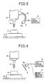
- the tool monitor includes a magnet 11 mounted on a spindle head 15 and an AE sensor 5 attached to spindle head 15 via magnet 11 and a supporting mechanism 12.
- the supporting mechanism 12 is a flexible member which does not conduct the AE signal and which holds the AE sensor 5 with its wave-reception surface 5a facing the machining zone of a drill 2.
- This embodiment also includes a tool damage detection means 6, as shown in Fig. 2, for processing the AE signal from the AE sensor 5.
- the AE sensor is connected to the spindle head 15 through the supporting mechanism 12 so that the AE signal generated in the machining zone can always be obtained from the AE sensor even in the case of a machine tool whose spindle head 15 is shifted and turned.
- AE sensor 5 is disposed apart from a spindle head 15 as in the first embodiment.
- this monitor includes a screen 13 facing a work piece 4 which is disposed in front of the AE sensor 5.
- This screen 13 includes a fine mesh to protect the AE sensor 5 from flying machined chips. In this arrangement, any contact of the AE sensor 5 with the chips is avoided so that the AE signal can be received without noise caused by collision of chips against AE sensor 5.
- This embodiment also includes a tool damage detection means 6 identical to that of the first embodiment.
- chips or dirt can collect on screen 13 which may prevent the AE signal from reaching AE sensor 5.
- a sensor sensitivity reduction detector 14 schematically indicated by a broken line in Fig. 4, can be employed.
- the sensitivity reduction detector 14 is shown in greater detail in Fig. 5.
- a gate signal is generated in a gate signal generator 21 at a predetermined cycle to intermittently drive an oscillator 22 which, in turn, outputs a signal with, for example, a frequency of about 200 KHz tuned to the reception frequency characteristics of the AE sensor 5 so as to drive the AE sensor 5 via a driving circuit 23.
- the AE sensor 5 transmits an AE signal to the screen 13 and detects the reflected wave signal from the screen 13 and feeds it to a detector 25 via an amplifier 24.
- the detector 25 performs an envelope detection of this signal and feeds its output to a comparator 26.
- the comparator 26 when a predetermined threshold level is exceeded, it is determined that the reflected wave signal level has been increased over the threshold, thus indicating an increase in dirt and chips on screen 13 over a desired level and a corresponding reduction in the reception sensitivity of AE sensor 5. Thus, the comparator 26 outputs a signal indicating this decrease in sensor sensitivity.
- the AE sensor 5 is used as an ultrasonic oscillator in this embodiment, it is also possible to use a transmission and a reception oscillator independent of the AE sensor.
- Fig. 6 is a sectional view showing an example of the AE sensor used in the third embodiment.
- the AE sensor includes an inner case 33 mounted within an outer housing 31 through a vibration-proof rubber member 32.
- a sensor device 35 held securely within this inner case 33 is a sensor device 35 supported by a sensor-retaining vibration-proof rubber member 34.
- a preamplifier 36 Connected to the back of the sensor device 35 is a preamplifier 36.
- a circular screen holder 38 is disposed around the peripheral edge of said outer housing 31 and a fine-mesh screen 13 is mounted on holder 38.
- Fig. 7 shows a tool monitor according to the fourth embodiment of this invention.
- an air nozzle 43 communicating with a compressed air source 41 via an air supply line 42 is disposed in the neighborhood of the AE sensor 5.
- air from the air nozzle 43 is directed generally from the AE sensor to the work piece 4 as shown.
- the compressed air source 41, air supply line 42 and air nozzle 43 constitute an air supply means for scattering away the chips from the front of the AE sensor 5.
- a plurality of air nozzles 43 can be provided around the machining zone.
- the outer housing 31 of AE sensor 5 can be connected to air supply line 42 and the inner case 33 can be provided with an air passage connected between supply line 42 and opening 37 so that the air from the air source is ejected from around the inner case 33 towards the screen 13 to thereby prevent contact of chips or dirt with the AE sensor.
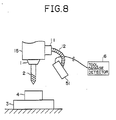
- the spindle head 15 is provided with an AE signal reception unit 51 via a magnet 11 and a supporting mechanism 12 just as in the second embodiment described hereinbefore.
- the AE signal reception unit 51 carries an AE sensor 5 via an elastic securing materal 53 within a rectangular housing 52 having a bottom opening.
- This housing 52 has a reflector 54 in its bottom position. Reflector 54 is adapted to reflect the AE signal and is disposed at an angle of 45 degrees from the bottom plane of the housing.
- the AE sensor 5 is fixed in position with its wave reception surface 5a facing the reflector 54 at an angle of 45 degrees.
- the AE signal from the machining zone is propagated to the AE sensor via the reflector 54 of the AE signal reception unit 51.
- chips, oil, dirt, etc. which are scattered during the machining operation may impinge only on the reflector 54 and, as a practical matter, do not reach the wave reception surface 5a of the AE sensor so that the AE signal can be received without interference by the noise generated on contact of the chips and other matter with the wave reception surface 5a.
- This embodiment also has a tool damage detector 6 which is similar to that of the foregoing embodiments and, therefore, is not described.
- Fig. 10 is a partial section view showing another example of the AE signal reception unit 51.
- a wave propagation duct 55 and the AE sensor 5 is installed within the duct.
- the wave propagation duct 55 is slightly curved so that chips produced in machining will not reach the wave reception surface of the AE sensor 5.
- the AE signal reception unit 51 moves and turns along with the spindle head 15, with the result that AE signals can be always obtained from the machining zone even in the case of a machine tool having a spindle that is shifted and turned.
- reception of AE signals without the influence by chips, dirt, etc. is assured.
Landscapes
- Engineering & Computer Science (AREA)
- Mechanical Engineering (AREA)
- Investigating Or Analyzing Materials By The Use Of Ultrasonic Waves (AREA)
- Machine Tool Sensing Apparatuses (AREA)
Applications Claiming Priority (4)
| Application Number | Priority Date | Filing Date | Title |
|---|---|---|---|
| JP71592/88 | 1988-03-24 | ||
| JP7159288 | 1988-03-24 | ||
| JP310756/88 | 1988-12-07 | ||
| JP63310756A JPH029555A (ja) | 1988-03-24 | 1988-12-07 | 工具損傷検出装置 |
Publications (2)
| Publication Number | Publication Date |
|---|---|
| EP0334341A2 true EP0334341A2 (de) | 1989-09-27 |
| EP0334341A3 EP0334341A3 (de) | 1990-11-07 |
Family
ID=26412703
Family Applications (1)
| Application Number | Title | Priority Date | Filing Date |
|---|---|---|---|
| EP19890105179 Withdrawn EP0334341A3 (de) | 1988-03-24 | 1989-03-22 | Werkzeugüberwachung |
Country Status (3)
| Country | Link |
|---|---|
| US (1) | US5076102A (de) |
| EP (1) | EP0334341A3 (de) |
| JP (1) | JPH029555A (de) |
Cited By (1)
| Publication number | Priority date | Publication date | Assignee | Title |
|---|---|---|---|---|
| EP1779949A1 (de) * | 2005-11-01 | 2007-05-02 | Volvo Lastvagnar Ab | Einrichtung und Verfahren zur Erfassung von Werkzeugbrüchen in Werkzeugmaschinen |
Families Citing this family (14)
| Publication number | Priority date | Publication date | Assignee | Title |
|---|---|---|---|---|
| US5485752A (en) * | 1992-09-25 | 1996-01-23 | Toyoda Koki Kabushiki Kaisha | Apparatus for detecting contact with rotating body |
| JP4804645B2 (ja) * | 2001-05-15 | 2011-11-02 | 株式会社テイエルブイ | 非接触式超音波及び温度測定装置 |
| US6964209B2 (en) * | 2001-05-22 | 2005-11-15 | 4B Elevator Components, Ltd. | Sensor mount attachment device |
| US7117741B2 (en) * | 2004-03-23 | 2006-10-10 | Lasson Technologies, Inc. | Method and device for ultrasonic vibration detection during high-performance machining |
| US7489856B2 (en) * | 2004-06-25 | 2009-02-10 | Nokia Corporation | Electrical device for automatically adjusting operating speed of a tool |
| DE102005037086A1 (de) * | 2005-08-03 | 2007-02-08 | Hauni Maschinenbau Ag | Überwachung eines Leimbilds auf einem Umhüllungsstreifen |
| JP2010271093A (ja) * | 2009-05-20 | 2010-12-02 | Jfe Steel Corp | 缶体のパネリング強度測定方法およびパネリング強度測定装置 |
| DE102010024794A1 (de) * | 2010-06-23 | 2011-12-29 | SMR Patents S.à.r.l. | Verfahren und Vorrichtung zur Kontrolle von Rastverbindungen |
| US9395277B2 (en) * | 2011-12-06 | 2016-07-19 | Kodak Alaris Inc. | Self-adjusting audio detection of medium jam |
| JP6019582B2 (ja) * | 2011-12-27 | 2016-11-02 | 株式会社ジェイテクト | 加工条件良否判定方法とその判定装置 |
| US10571367B1 (en) * | 2014-05-05 | 2020-02-25 | Aaron G. Silverberg | Power tool usage auditor |
| US10295475B2 (en) | 2014-09-05 | 2019-05-21 | Rolls-Royce Corporation | Inspection of machined holes |
| US10228669B2 (en) | 2015-05-27 | 2019-03-12 | Rolls-Royce Corporation | Machine tool monitoring |
| JP2022052946A (ja) * | 2020-09-24 | 2022-04-05 | 株式会社東芝 | 塑性加工異常検出装置及び塑性加工異常検出方法 |
Family Cites Families (15)
| Publication number | Priority date | Publication date | Assignee | Title |
|---|---|---|---|---|
| US3104826A (en) * | 1963-09-24 | morris | ||
| US3956932A (en) * | 1975-01-29 | 1976-05-18 | Nasa | Wind sensor |
| US4036057A (en) * | 1975-04-15 | 1977-07-19 | Acoustic Emission Technology Corporation | Automatic threshold control means and the use thereof |
| US4269065A (en) * | 1978-03-01 | 1981-05-26 | Clark Robert N | Ultrasonic detector apparatus |
| US4274289A (en) * | 1979-08-29 | 1981-06-23 | Amf Incorporated | Transducer positioning system for ultrasonic tire testing apparatus |
| US4326155A (en) * | 1980-06-03 | 1982-04-20 | Griebeler Elmer L | Shockwave probe |
| ATE18705T1 (de) * | 1981-08-20 | 1986-04-15 | De La Rue Syst | Geraet zur feststellung des zustandes eines blattes. |
| US4596953A (en) * | 1982-04-14 | 1986-06-24 | Daidotokushuko Kabushikikaisha | Apparatus for scanning a material for detection of flaws and having material axis deviation detection |
| US4574633A (en) * | 1983-02-04 | 1986-03-11 | Citizen Watch Company Limited | Apparatus for detecting tool damage in automatically controlled machine tool |
| US4495810A (en) * | 1983-04-20 | 1985-01-29 | General Electric Company | Probe mounting system |
| DE3573333D1 (en) * | 1984-05-18 | 1989-11-02 | Omron Tateisi Electronics Co | Tool monitoring system |
| DE3434461A1 (de) * | 1984-09-20 | 1986-03-27 | Roland Electronic Horst Nauditt GmbH, 7538 Keltern | Optoelektronische werkzeugbruchueberwachung |
| JPS61132858A (ja) * | 1984-11-30 | 1986-06-20 | Omron Tateisi Electronics Co | 工具折損検出装置 |
| US4704693A (en) * | 1985-06-28 | 1987-11-03 | General Electric Company | Acoustic tool touch detector with minimized detection delay |
| DE3600466A1 (de) * | 1986-01-10 | 1987-07-16 | Otto Zettl | Spannfutter fuer rotierende werkzeuge |
-
1988
- 1988-12-07 JP JP63310756A patent/JPH029555A/ja active Pending
-
1989
- 1989-03-22 EP EP19890105179 patent/EP0334341A3/de not_active Withdrawn
-
1991
- 1991-01-30 US US07/649,298 patent/US5076102A/en not_active Expired - Fee Related
Cited By (1)
| Publication number | Priority date | Publication date | Assignee | Title |
|---|---|---|---|---|
| EP1779949A1 (de) * | 2005-11-01 | 2007-05-02 | Volvo Lastvagnar Ab | Einrichtung und Verfahren zur Erfassung von Werkzeugbrüchen in Werkzeugmaschinen |
Also Published As
| Publication number | Publication date |
|---|---|
| US5076102A (en) | 1991-12-31 |
| EP0334341A3 (de) | 1990-11-07 |
| JPH029555A (ja) | 1990-01-12 |
Similar Documents
| Publication | Publication Date | Title |
|---|---|---|
| US5076102A (en) | Tool monitor | |
| US4607254A (en) | Flow detector | |
| US5058433A (en) | Workpiece inspection | |
| US5917776A (en) | Means for reducing minimum sensing distance of an ultrasonic proximity sensor | |
| US4558686A (en) | Machining device equipped with blade inspecting means | |
| CN109154521A (zh) | 具有反射体的超声波液位传感器 | |
| US4677595A (en) | Ultrasonic vehicle rangefinder | |
| US5036706A (en) | Sonic web break detector | |
| JPH0615136B2 (ja) | 工作機械における工具の工作物に向かつての送りを制御する方法及び装置 | |
| US20030060920A1 (en) | Detection of vibrations in mechanical systems | |
| US5850184A (en) | Ultrasonic tool confirmation sensor | |
| US7357031B2 (en) | Precision sensor assembly for rotating members in a machine tool | |
| JP7848643B2 (ja) | 超音波装置、及び媒体搬送装置 | |
| JPH03294150A (ja) | 工具異常検出方法 | |
| JPH06114689A (ja) | 印刷配線板外形加工機の工具折損検出装置 | |
| KR100539749B1 (ko) | 초음파 센서의 진동 차폐 장치 | |
| SU1077768A1 (ru) | Устройство дл определени момента касани детали режущим инструментом | |
| JPH03221331A (ja) | ネジ保持状態検出機構 | |
| JPS5828451A (ja) | 工具刃先損傷の検出方法 | |
| JPH045542A (ja) | 工具異常検出方法 | |
| JPH05177512A (ja) | 切削中の表面粗さ判定方法 | |
| JPH03146141A (ja) | 精米機の米粒漏洩検出装置 | |
| JPS5840246A (ja) | 工具刃先損傷の検出方法 | |
| JPS61164761A (ja) | 工具折損検出装置 | |
| JPH066253B2 (ja) | 工具折損検出装置 |
Legal Events
| Date | Code | Title | Description |
|---|---|---|---|
| PUAI | Public reference made under article 153(3) epc to a published international application that has entered the european phase |
Free format text: ORIGINAL CODE: 0009012 |
|
| 17P | Request for examination filed |
Effective date: 19890322 |
|
| AK | Designated contracting states |
Kind code of ref document: A2 Designated state(s): AT BE CH DE ES FR GB GR IT LI NL SE |
|
| PUAL | Search report despatched |
Free format text: ORIGINAL CODE: 0009013 |
|
| AK | Designated contracting states |
Kind code of ref document: A3 Designated state(s): AT BE CH DE ES FR GB GR IT LI NL SE |
|
| 17Q | First examination report despatched |
Effective date: 19910909 |
|
| STAA | Information on the status of an ep patent application or granted ep patent |
Free format text: STATUS: THE APPLICATION IS DEEMED TO BE WITHDRAWN |
|
| 18D | Application deemed to be withdrawn |
Effective date: 19920121 |