EP0336028A1 - Rouleau chauffant pour l'électrophotographie - Google Patents
Rouleau chauffant pour l'électrophotographie Download PDFInfo
- Publication number
- EP0336028A1 EP0336028A1 EP88303032A EP88303032A EP0336028A1 EP 0336028 A1 EP0336028 A1 EP 0336028A1 EP 88303032 A EP88303032 A EP 88303032A EP 88303032 A EP88303032 A EP 88303032A EP 0336028 A1 EP0336028 A1 EP 0336028A1
- Authority
- EP
- European Patent Office
- Prior art keywords
- heat roll
- temperature
- core
- conductive material
- electrophotography
- Prior art date
- Legal status (The legal status is an assumption and is not a legal conclusion. Google has not performed a legal analysis and makes no representation as to the accuracy of the status listed.)
- Granted
Links
- 239000004020 conductor Substances 0.000 claims abstract description 17
- 238000010438 heat treatment Methods 0.000 claims abstract description 11
- 229910001209 Low-carbon steel Inorganic materials 0.000 claims abstract description 8
- 229910052782 aluminium Inorganic materials 0.000 claims abstract description 7
- XAGFODPZIPBFFR-UHFFFAOYSA-N aluminium Chemical compound [Al] XAGFODPZIPBFFR-UHFFFAOYSA-N 0.000 claims abstract description 7
- 229910045601 alloy Inorganic materials 0.000 claims description 4
- 239000000956 alloy Substances 0.000 claims description 4
- 206010037660 Pyrexia Diseases 0.000 claims 1
- 238000009826 distribution Methods 0.000 abstract description 12
- 229910000838 Al alloy Inorganic materials 0.000 abstract description 6
- 230000000694 effects Effects 0.000 abstract description 6
- RYGMFSIKBFXOCR-UHFFFAOYSA-N Copper Chemical compound [Cu] RYGMFSIKBFXOCR-UHFFFAOYSA-N 0.000 abstract description 3
- 229910000881 Cu alloy Inorganic materials 0.000 abstract description 3
- 239000010949 copper Substances 0.000 abstract description 3
- 229910052802 copper Inorganic materials 0.000 abstract description 3
- 230000002093 peripheral effect Effects 0.000 abstract description 2
- 238000000034 method Methods 0.000 description 7
- PNEYBMLMFCGWSK-UHFFFAOYSA-N aluminium oxide Inorganic materials [O-2].[O-2].[O-2].[Al+3].[Al+3] PNEYBMLMFCGWSK-UHFFFAOYSA-N 0.000 description 5
- 239000000919 ceramic Substances 0.000 description 5
- 229910052593 corundum Inorganic materials 0.000 description 3
- 229910001845 yogo sapphire Inorganic materials 0.000 description 3
- CWYNVVGOOAEACU-UHFFFAOYSA-N Fe2+ Chemical compound [Fe+2] CWYNVVGOOAEACU-UHFFFAOYSA-N 0.000 description 2
- 230000000052 comparative effect Effects 0.000 description 2
- 238000010586 diagram Methods 0.000 description 2
- 239000000463 material Substances 0.000 description 2
- 239000010935 stainless steel Substances 0.000 description 2
- 229910001220 stainless steel Inorganic materials 0.000 description 2
- 229910000906 Bronze Inorganic materials 0.000 description 1
- 229910000831 Steel Inorganic materials 0.000 description 1
- 239000004809 Teflon Substances 0.000 description 1
- 229920006362 Teflon® Polymers 0.000 description 1
- 239000000853 adhesive Substances 0.000 description 1
- 230000001070 adhesive effect Effects 0.000 description 1
- 239000010974 bronze Substances 0.000 description 1
- VNNRSPGTAMTISX-UHFFFAOYSA-N chromium nickel Chemical compound [Cr].[Ni] VNNRSPGTAMTISX-UHFFFAOYSA-N 0.000 description 1
- 239000002131 composite material Substances 0.000 description 1
- KUNSUQLRTQLHQQ-UHFFFAOYSA-N copper tin Chemical compound [Cu].[Sn] KUNSUQLRTQLHQQ-UHFFFAOYSA-N 0.000 description 1
- 230000006866 deterioration Effects 0.000 description 1
- 238000004299 exfoliation Methods 0.000 description 1
- 229910052736 halogen Inorganic materials 0.000 description 1
- 150000002367 halogens Chemical class 0.000 description 1
- 239000011810 insulating material Substances 0.000 description 1
- 238000009413 insulation Methods 0.000 description 1
- 238000004519 manufacturing process Methods 0.000 description 1
- 229910001120 nichrome Inorganic materials 0.000 description 1
- 229920002050 silicone resin Polymers 0.000 description 1
- 229910000679 solder Inorganic materials 0.000 description 1
- 239000007921 spray Substances 0.000 description 1
- 239000010959 steel Substances 0.000 description 1
- 229910000859 α-Fe Inorganic materials 0.000 description 1
Images



Classifications
-
- G—PHYSICS
- G03—PHOTOGRAPHY; CINEMATOGRAPHY; ANALOGOUS TECHNIQUES USING WAVES OTHER THAN OPTICAL WAVES; ELECTROGRAPHY; HOLOGRAPHY
- G03G—ELECTROGRAPHY; ELECTROPHOTOGRAPHY; MAGNETOGRAPHY
- G03G15/00—Apparatus for electrographic processes using a charge pattern
- G03G15/20—Apparatus for electrographic processes using a charge pattern for fixing, e.g. by using heat
- G03G15/2003—Apparatus for electrographic processes using a charge pattern for fixing, e.g. by using heat using heat
- G03G15/2014—Apparatus for electrographic processes using a charge pattern for fixing, e.g. by using heat using heat using contact heat
- G03G15/2053—Structural details of heat elements, e.g. structure of roller or belt, eddy current, induction heating
- G03G15/2057—Structural details of heat elements, e.g. structure of roller or belt, eddy current, induction heating relating to the chemical composition of the heat element and layers thereof
Definitions
- the present invention relates to improvements of a heat roll for electrophotography in which a bonding layer, an insulating layer, a resistance layer, and a surface insulating layer are provided sequentially on an outer surface of a core formed into a hollow tabular shape, and heat is generated by energization of the resistance layer so as to fix a toner image on a recording medium.
- a conventionally known heat roll used in an electrophotographic printing system for thermally fixing a toner image transferred onto a recording medium such as copying paper is arranged such that a halogen lamp is provided in a hollow tubular core as a heat source to effect heating.
- a heat roll of this type there are drawbacks in that the rate of power consumption is large, and that a warming-up time required until the start of copying after energization is long.
- its outside diameter cannot be made small since the lamp is provided inside it.
- a direct-heating heat roll is known in which a heating resistor is arranged on the outer surface of the core. Fig.
- Electrode rings 6 are respectively fixed to opposite end portions of the resistance layer 5 and are electrically connected to the resistance layer 5.
- a feeder brush 7 is disposed such as to slidably abut against the outer periphery of each of the electrode rings 6.
- a surface insulating layer 8 is disposed on the outer periphery of the resistance layer 5 to electrically protect the insulating layer 5 and prevent the insulating layer 5 from becoming damaged by external force.
- a ceramic is used for the insulating layer 8 and the resistance layer 5. Incidentally, in cases where the core is formed of an insulating material, the bonding layer 3 and the insulating layer 4 may not be provided.
- a ceramic is used for the insulating layer or the resistance layer, as for the material of the core, it is necessary to use one having a coefficient of thermal expansion which is close to that of the ceramic (generally, 5 to 10 x 10 ⁇ 6/°C). If an aluminum alloy which has a large coefficient of thermal expansion is used as the core, cracks occur in the ceramic owing to repetition of thermal load during production or usage thereof, resulting in deterioration of its electrical properties and breakage of the resistor. In terms of economic efficiency, a ferrous alloy (e.g. mild steel, ferrite-based stainless steel, or martensite-based stainless steel) is most desirable. In addition, there are cases where an insulating ceramic formed of alumina or the like is used.
- a ferrous alloy e.g. mild steel, ferrite-based stainless steel, or martensite-based stainless steel
- an object of the present invention is to provide a heat roll for electrophotography which is capable of alleviating effects which are attributable to a difference in the coefficients of thermal expansion and of accelerating a rise in the temperature of the heat roll up to a predetermined temperature, thereby overcoming the above-described drawbacks of the prior art.
- a heat roll for electrophotography having a heating resistor, wherein a bonding layer, an insulating layer, a resistance layer, and a surface insulating layer are sequentially provided on an outer surface of a hollow cylindrical core, and a bearing member for fitting with a bearing is fitted at each opposite end of the heat roll.
- a pipe or a round bar formed of aluminum, an aluminum alloy, copper, a copper alloy, or the like which has a greater coefficient of thermal conductivity than that of mild steel is disposed inside the core.
- a gap of 0.2 mm or more is preferably provided between the inner surface of the core and the outer surface of a member formed of a high-temperature conductive material so as to alleviate effects that are attributable to a difference in the coefficients of thermal expansion during a temperature rise.
- an arrangement is preferably provided in such a manner as to substantially prevent the axial movement of the pipe or the round bar. The above-described arrangements produce the effect of preventing the exfoliation of the insulating film, the resistance film, etc.
- the high-temperature conductive material is provided inside the heat roll, there is an advantage of making the temperature uniform. Furthermore, if the gap of 0.2 mm or more is provided, the temperature rise up to a predetermined temperature of the heat roll is accelerated as compared with a case where a smaller gap is provided.
- Fig. 1 is a cross-sectional view of a heat roll in accordance with the present invention.
- a pipe 1 is made of a high-temperature conductive material such as aluminum and has a thickness of, for instance, 2 to 3 mm.
- the material may be an aluminum alloy, copper, a copper alloy, or the like. If it is necessary, a round bar may be used in place of the pipe 1.
- a core 2 made of mild steel is formed into a hollow tubular shape, and a gap of 0.2 mm or more is provided between the core 2 and the pipe 1.
- An outer surface of this core are sequentially coated with a bonding layer 3 made of Ni-Al-Mo with a thickness of 25 ⁇ m, an insulating layer 4 made of Al2O3 with a thickness of 300 ⁇ m or thereabout, a resistance layer 5, i.e., a heating resistor, made of Al2O3 + NiCr with a thickness of 70 ⁇ m or thereabout, and a surface insulating layer 8, i.e., an insulating film, made of Al2O3 with a thickness of 100 ⁇ m or thereabout.
- An electrode ring 6 made of a conductive material such as aluminum bronze is provided at each opposite end of the resistance layer 5 such as to project therefrom, and a feeder brush 7 is provided thereon such as to be slidable.
- an outer peripheral surface of the surface insulating layer 8 is coated with Teflon with a thickness of approximately 30 ⁇ m, while the end surface portions of the insulating layer 4 that are outside the electrode rings 6 are provided with insulation by means of silicone resin.
- the heat roll is capable of demonstrating its function.
- a pipe made of aluminum (A 5056) and having an outside diameter of 36.4 mm, an inside diameter of 33.8 mm, and a length of 350 mm was inserted into a conventional heat roll using a core made of mild steel and having an outside diameter of 40 mm, an inside diameter of 37.2 mm, and a length of 330 mm between electrodes in such a manner as to substantially correspond with the distance between the electrodes.
- a comparison was made between the temperature distribution in this case and that of a conventional structure in which the pipe was not provided. The results are shown in Fig. 2.
- the dotted lines indicate temperature distributions obtained when the temperature of the heat roll in accordance with the invention became stable and immediately after 100 sheets of A-4 size paper were continuously fed.
- solid lines indicate temperature distributions in the case of a conventional heat roll which was not provided with the high-temperature conductive material.
- the present invention displays a large effect in improving the temperature distribution, and contributes greatly to the improvement of the fixing performance.
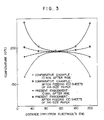
- a round bar made of an aluminum alloy (A 5056) and having an outside diameter of 11.8 mm was inserted into a conventional heat roll using a core made of mild steel and having an outside diameter of 15 mm, an inside diameter of 12.6 mm, and a length of 220 mm between electrodes in such a manner as to substantially correspond with the distance between the electrodes.
- a comparison was made between the temperature distribution in this case and that of a conventional structure in which the round bar was not provided.
- the results are shown in Fig. 3.
- the dotted lines indicate temperature distributions obtained when the temperature of the heat roll in accordance with the invention became stable and immediately after 100 sheets of A-4 size paper were continuously fed.
- solid lines indicate temperature distributions in the case of a conventional heat roll which was not provided with the high-temperature conductive material.
- the present invention enables a substantial improvement in the temperature distribution.
- a round bar made of an aluminum alloy (A 5056) and having an outside diameter of 16.8 mm was inserted into a conventional heat roll having an outside diameter of 20.0 mm, an inside diameter of 17.0 mm, and a length of 220 mm between electrodes in such a manner as to substantially correspond with the distance between the electrodes, and a test was conducted in the same way as Example 2. Consequently, results similar to those of Example 2 were obtained.
- the inner high-temperature conductive material may be extended to the end portions of the roll, or a composite pipe may be used.
Landscapes
- Physics & Mathematics (AREA)
- General Physics & Mathematics (AREA)
- Fixing For Electrophotography (AREA)
- Control Of Resistance Heating (AREA)
- Rolls And Other Rotary Bodies (AREA)
Priority Applications (1)
| Application Number | Priority Date | Filing Date | Title |
|---|---|---|---|
| DE8888303032T DE3876980T2 (de) | 1986-10-23 | 1988-04-06 | Beheizbare rolle fuer die elektrofotografie. |
Applications Claiming Priority (1)
| Application Number | Priority Date | Filing Date | Title |
|---|---|---|---|
| JP61252241A JPS63106682A (ja) | 1986-10-23 | 1986-10-23 | 電子写真用ヒ−トロ−ル |
Publications (2)
| Publication Number | Publication Date |
|---|---|
| EP0336028A1 true EP0336028A1 (fr) | 1989-10-11 |
| EP0336028B1 EP0336028B1 (fr) | 1992-12-23 |
Family
ID=17234475
Family Applications (1)
| Application Number | Title | Priority Date | Filing Date |
|---|---|---|---|
| EP88303032A Expired EP0336028B1 (fr) | 1986-10-23 | 1988-04-06 | Rouleau chauffant pour l'électrophotographie |
Country Status (4)
| Country | Link |
|---|---|
| US (1) | US4888464A (fr) |
| EP (1) | EP0336028B1 (fr) |
| JP (1) | JPS63106682A (fr) |
| DE (1) | DE3876980T2 (fr) |
Cited By (1)
| Publication number | Priority date | Publication date | Assignee | Title |
|---|---|---|---|---|
| GB2302841A (en) * | 1995-07-04 | 1997-02-05 | Samsung Electronics Co Ltd | Fixing rollers for electrophotography |
Families Citing this family (26)
| Publication number | Priority date | Publication date | Assignee | Title |
|---|---|---|---|---|
| JPS63106682A (ja) * | 1986-10-23 | 1988-05-11 | Hitachi Metals Ltd | 電子写真用ヒ−トロ−ル |
| US5270777A (en) * | 1987-12-18 | 1993-12-14 | Canon Kabushiki Kaisha | Fixing apparatus having heat conducting member inside a fixing roller |
| JPH01161389A (ja) * | 1987-12-18 | 1989-06-26 | Canon Inc | 定着ローラ |
| JP2762710B2 (ja) | 1990-06-25 | 1998-06-04 | 住友金属工業株式会社 | 熱クラウン抑制ハースロール |
| FI101556B1 (fi) * | 1990-10-08 | 1998-07-15 | Yamauchi Corp | Paperikoneen puristustela |
| WO1992019809A1 (fr) * | 1991-05-03 | 1992-11-12 | Sulzer-Escher Wyss Gmbh | Rouleau a souplesse variable et son utilisation |
| US5173736A (en) * | 1991-09-06 | 1992-12-22 | Xerox Corporation | Apparatus and method for fusing marking particles onto a support member |
| US5153411A (en) * | 1992-02-28 | 1992-10-06 | Eastman Kodak Company | Fuser roller having surface-temperature reducing member |
| JP3102132B2 (ja) * | 1992-03-31 | 2000-10-23 | 住友金属工業株式会社 | ヒートクラウン抑制炉内ロール |
| EP0578971B1 (fr) * | 1992-06-22 | 1995-09-27 | Walzen Irle GmbH | Rouleau pour calandre à chauffage électrique |
| US5609553A (en) * | 1992-11-09 | 1997-03-11 | American Roller Company | Ceramic roller for ESA printing and coating |
| US5616263A (en) * | 1992-11-09 | 1997-04-01 | American Roller Company | Ceramic heater roller |
| US5420395A (en) * | 1992-11-09 | 1995-05-30 | American Roller Company | Ceramic heater roller with zone heating |
| US6069346A (en) * | 1993-01-12 | 2000-05-30 | American Roller Company | Ceramic heater roller with ground shield and fault detection |
| EP0813632B1 (fr) * | 1995-05-09 | 1998-11-11 | Eduard Küsters Maschinenfabrik GmbH & Co. KG | Rouleau chauffant |
| US5722025A (en) * | 1995-10-24 | 1998-02-24 | Minolta Co., Ltd. | Fixing device |
| JP3387328B2 (ja) * | 1996-09-03 | 2003-03-17 | ミノルタ株式会社 | 定着装置 |
| DE19635845C1 (de) * | 1996-09-04 | 1998-06-10 | Voith Sulzer Finishing Gmbh | Kalanderwalze mit einem Bezug aus elastischem Kunststoff |
| TW422895B (en) * | 1997-10-28 | 2001-02-21 | Sms Scholoemann Siemag Aktieng | Current roller for electrolytic stratification device for strip |
| US6137087A (en) * | 1997-12-26 | 2000-10-24 | Brother Kogyo Kabushiki Kaisha | Thermal roller for thermal fixing device |
| US6122480A (en) * | 1999-09-27 | 2000-09-19 | Xerox Corporation | Metallic core rapid warm-up fuser roller |
| DE10085449T1 (de) * | 2000-03-15 | 2003-01-30 | Fujitsu Ltd | Fixiervorrichtung |
| KR100388997B1 (ko) * | 2001-02-22 | 2003-06-25 | 삼성전자주식회사 | 전자사진 방식 인쇄기의 가열롤러 조립체 |
| MXPA04008898A (es) * | 2002-03-13 | 2005-06-20 | Watlow Electric Mfg | Dispositivo calentador de canal caliente y su metodo de fabricacion. |
| EP2290469A1 (fr) * | 2009-08-20 | 2011-03-02 | Samsung Electronics Co., Ltd. | Dispositif de fusion incluant une couche de chauffage résistante et appareil de formation d'images incluant le dispositif de fusion |
| US20110070006A1 (en) * | 2009-09-22 | 2011-03-24 | Kabushiki Kaisha Toshiba | Temperature equalizing roller and fixing device |
Citations (3)
| Publication number | Priority date | Publication date | Assignee | Title |
|---|---|---|---|---|
| EP0240730A1 (fr) * | 1986-03-07 | 1987-10-14 | Hitachi Metals, Ltd. | Rouleau à chauffage directe pour la fixation par fusion d'images par agent de contraste |
| EP0261511A2 (fr) * | 1986-09-13 | 1988-03-30 | Canon Kabushiki Kaisha | Elément rotatif élastique et appareil de fixage utilisant cet élément |
| JPS63106682A (ja) * | 1986-10-23 | 1988-05-11 | Hitachi Metals Ltd | 電子写真用ヒ−トロ−ル |
Family Cites Families (8)
| Publication number | Priority date | Publication date | Assignee | Title |
|---|---|---|---|---|
| US4395109A (en) * | 1979-06-11 | 1983-07-26 | Tokyo Shibaura Denki Kabushiki Kaisha | Fixing device for electronic duplicator machine |
| JPS56158359A (en) * | 1980-05-12 | 1981-12-07 | Canon Inc | Fixing roller |
| JPS58169168A (ja) * | 1982-03-31 | 1983-10-05 | Copyer Co Ltd | ヒ−トロ−ル |
| JPS58198071A (ja) * | 1982-05-14 | 1983-11-17 | Ricoh Co Ltd | 加熱定着装置 |
| JPS58203471A (ja) * | 1982-05-21 | 1983-11-26 | Hitachi Metals Ltd | ヒ−トロ−ル定着装置 |
| JPS59155873A (ja) * | 1983-02-24 | 1984-09-05 | Hitachi Metals Ltd | 加熱定着装置 |
| US4714819A (en) * | 1985-07-17 | 1987-12-22 | Hitachi Metals, Ltd. | Directly heating fixing apparatus having current collecting bearings |
| US4801968A (en) * | 1986-03-18 | 1989-01-31 | Kabushiki Kaisha Toshiba | Fixing device including a heat roller having a device for heating a region of the roller corresponding to the width of an image forming medium |
-
1986
- 1986-10-23 JP JP61252241A patent/JPS63106682A/ja active Pending
-
1988
- 1988-04-05 US US07/177,982 patent/US4888464A/en not_active Expired - Fee Related
- 1988-04-06 EP EP88303032A patent/EP0336028B1/fr not_active Expired
- 1988-04-06 DE DE8888303032T patent/DE3876980T2/de not_active Expired - Fee Related
Patent Citations (3)
| Publication number | Priority date | Publication date | Assignee | Title |
|---|---|---|---|---|
| EP0240730A1 (fr) * | 1986-03-07 | 1987-10-14 | Hitachi Metals, Ltd. | Rouleau à chauffage directe pour la fixation par fusion d'images par agent de contraste |
| EP0261511A2 (fr) * | 1986-09-13 | 1988-03-30 | Canon Kabushiki Kaisha | Elément rotatif élastique et appareil de fixage utilisant cet élément |
| JPS63106682A (ja) * | 1986-10-23 | 1988-05-11 | Hitachi Metals Ltd | 電子写真用ヒ−トロ−ル |
Non-Patent Citations (1)
| Title |
|---|
| PATENT ABSTRACTS OF JAPAN, vol. 9, no. 9 (P-327)[1732], 16th January 1985; & JP-A-59 155 873 (HITACHI KINZOKU K.K.) 05-09-1984 * |
Cited By (2)
| Publication number | Priority date | Publication date | Assignee | Title |
|---|---|---|---|---|
| GB2302841A (en) * | 1995-07-04 | 1997-02-05 | Samsung Electronics Co Ltd | Fixing rollers for electrophotography |
| GB2302841B (en) * | 1995-07-04 | 1997-09-17 | Samsung Electronics Co Ltd | Heating rollers for electrophotographic apparatus |
Also Published As
| Publication number | Publication date |
|---|---|
| EP0336028B1 (fr) | 1992-12-23 |
| DE3876980D1 (de) | 1993-02-04 |
| US4888464A (en) | 1989-12-19 |
| DE3876980T2 (de) | 1993-04-29 |
| JPS63106682A (ja) | 1988-05-11 |
Similar Documents
| Publication | Publication Date | Title |
|---|---|---|
| EP0336028A1 (fr) | Rouleau chauffant pour l'électrophotographie | |
| KR940001086B1 (ko) | 직접 가열식 토우너상 정착 롤 | |
| KR940001087B1 (ko) | 직접 가열식 토우너상 정착롤러 | |
| EP0262833B1 (fr) | Rouleau thermique de fixage pour utilisation dans une machine à copier et méthode en vue de sa fabrication | |
| US4874927A (en) | Heating roll for fixing toner | |
| JPH061397B2 (ja) | コロナ装置 | |
| US5377070A (en) | Charging apparatus for photoreceptor | |
| CN1360232A (zh) | 电子照相成像装置的定影辊组件 | |
| KR920006988B1 (ko) | 전자사진용 가열 롤 | |
| EP0903646B1 (fr) | Elément chauffant en céramique pour le fixage d'images de toner | |
| JPH06128623A (ja) | 加熱ロール | |
| JP3281750B2 (ja) | 円筒状ヒータ及び定着用ヒートローラ | |
| JPH07302010A (ja) | 定着用加熱ローラ | |
| JPS62251780A (ja) | 電子写真用ヒ−トロ−ル | |
| JP3441325B2 (ja) | 定着用ヒートローラ及びその製造方法 | |
| JP2652162B2 (ja) | 熱定着ローラの製造方法 | |
| JP3281749B2 (ja) | 定着用ヒートローラ | |
| JPH10221984A (ja) | 定着器用セラミックスヒーター及び加熱定着装置 | |
| JPH06175528A (ja) | 熱定着装置 | |
| JPH08278716A (ja) | 通電型定着ロール及びこの定着ロールの給電装置 | |
| JPH1140320A (ja) | 加熱ローラ | |
| JPS63146375A (ja) | ロ−ルヒ−タ | |
| JPS6385676A (ja) | 電子写真用ヒ−トロ−ル | |
| JPH0658580B2 (ja) | 加熱定着ロ−ル | |
| JPH06180541A (ja) | 画像形成装置用熱定着ローラーおよび画像形成装置 |
Legal Events
| Date | Code | Title | Description |
|---|---|---|---|
| PUAI | Public reference made under article 153(3) epc to a published international application that has entered the european phase |
Free format text: ORIGINAL CODE: 0009012 |
|
| AK | Designated contracting states |
Kind code of ref document: A1 Designated state(s): DE FR GB IT |
|
| 17P | Request for examination filed |
Effective date: 19891208 |
|
| 17Q | First examination report despatched |
Effective date: 19911104 |
|
| GRAA | (expected) grant |
Free format text: ORIGINAL CODE: 0009210 |
|
| AK | Designated contracting states |
Kind code of ref document: B1 Designated state(s): DE FR GB IT |
|
| PG25 | Lapsed in a contracting state [announced via postgrant information from national office to epo] |
Ref country code: IT Free format text: LAPSE BECAUSE OF FAILURE TO SUBMIT A TRANSLATION OF THE DESCRIPTION OR TO PAY THE FEE WITHIN THE PRE;WARNING: LAPSES OF ITALIAN PATENTS WITH EFFECTIVE DATE BEFORE 2007 MAY HAVE OCCURRED AT ANY TIME BEFORE 2007. THE CORRECT EFFECTIVE DATE MAY BE DIFFERENT FROM THE ONE RECORDED.SCRIBED TIME-LIMIT Effective date: 19921223 Ref country code: FR Effective date: 19921223 |
|
| REF | Corresponds to: |
Ref document number: 3876980 Country of ref document: DE Date of ref document: 19930204 |
|
| PGFP | Annual fee paid to national office [announced via postgrant information from national office to epo] |
Ref country code: DE Payment date: 19930326 Year of fee payment: 6 |
|
| PG25 | Lapsed in a contracting state [announced via postgrant information from national office to epo] |
Ref country code: GB Effective date: 19930406 |
|
| EN | Fr: translation not filed | ||
| PLBE | No opposition filed within time limit |
Free format text: ORIGINAL CODE: 0009261 |
|
| STAA | Information on the status of an ep patent application or granted ep patent |
Free format text: STATUS: NO OPPOSITION FILED WITHIN TIME LIMIT |
|
| GBPC | Gb: european patent ceased through non-payment of renewal fee |
Effective date: 19930406 |
|
| 26N | No opposition filed | ||
| PG25 | Lapsed in a contracting state [announced via postgrant information from national office to epo] |
Ref country code: DE Effective date: 19950103 |