EP0336455A2 - Epurateur d'air - Google Patents
Epurateur d'air Download PDFInfo
- Publication number
- EP0336455A2 EP0336455A2 EP89110273A EP89110273A EP0336455A2 EP 0336455 A2 EP0336455 A2 EP 0336455A2 EP 89110273 A EP89110273 A EP 89110273A EP 89110273 A EP89110273 A EP 89110273A EP 0336455 A2 EP0336455 A2 EP 0336455A2
- Authority
- EP
- European Patent Office
- Prior art keywords
- fan
- air
- shaped channel
- cleaning system
- casing
- Prior art date
- Legal status (The legal status is an assumption and is not a legal conclusion. Google has not performed a legal analysis and makes no representation as to the accuracy of the status listed.)
- Granted
Links
- 238000004140 cleaning Methods 0.000 claims abstract description 25
- 238000007789 sealing Methods 0.000 claims abstract description 12
- 239000007788 liquid Substances 0.000 claims abstract description 9
- 230000002265 prevention Effects 0.000 claims description 7
- 239000006096 absorbing agent Substances 0.000 claims description 5
- 238000005192 partition Methods 0.000 description 7
- 239000004033 plastic Substances 0.000 description 6
- 229920003023 plastic Polymers 0.000 description 6
- 229910052782 aluminium Inorganic materials 0.000 description 3
- XAGFODPZIPBFFR-UHFFFAOYSA-N aluminium Chemical compound [Al] XAGFODPZIPBFFR-UHFFFAOYSA-N 0.000 description 3
- 238000011045 prefiltration Methods 0.000 description 3
- 230000003068 static effect Effects 0.000 description 3
- 238000009827 uniform distribution Methods 0.000 description 3
- 238000009423 ventilation Methods 0.000 description 3
- XEEYBQQBJWHFJM-UHFFFAOYSA-N Iron Chemical compound [Fe] XEEYBQQBJWHFJM-UHFFFAOYSA-N 0.000 description 2
- 238000009826 distribution Methods 0.000 description 2
- 238000007689 inspection Methods 0.000 description 2
- 230000001105 regulatory effect Effects 0.000 description 2
- MQIUGAXCHLFZKX-UHFFFAOYSA-N Di-n-octyl phthalate Natural products CCCCCCCCOC(=O)C1=CC=CC=C1C(=O)OCCCCCCCC MQIUGAXCHLFZKX-UHFFFAOYSA-N 0.000 description 1
- 229920005830 Polyurethane Foam Polymers 0.000 description 1
- 238000004887 air purification Methods 0.000 description 1
- BJQHLKABXJIVAM-UHFFFAOYSA-N bis(2-ethylhexyl) phthalate Chemical compound CCCCC(CC)COC(=O)C1=CC=CC=C1C(=O)OCC(CC)CCCC BJQHLKABXJIVAM-UHFFFAOYSA-N 0.000 description 1
- 230000008859 change Effects 0.000 description 1
- YACLQRRMGMJLJV-UHFFFAOYSA-N chloroprene Chemical compound ClC(=C)C=C YACLQRRMGMJLJV-UHFFFAOYSA-N 0.000 description 1
- 150000001875 compounds Chemical class 0.000 description 1
- 239000011491 glass wool Substances 0.000 description 1
- 238000009434 installation Methods 0.000 description 1
- 229910052742 iron Inorganic materials 0.000 description 1
- 238000012423 maintenance Methods 0.000 description 1
- 238000004519 manufacturing process Methods 0.000 description 1
- 229910052751 metal Inorganic materials 0.000 description 1
- 239000002184 metal Substances 0.000 description 1
- 238000012986 modification Methods 0.000 description 1
- 230000004048 modification Effects 0.000 description 1
- 239000002245 particle Substances 0.000 description 1
- 239000002984 plastic foam Substances 0.000 description 1
- 229920006327 polystyrene foam Polymers 0.000 description 1
- 239000011496 polyurethane foam Substances 0.000 description 1
- 230000009467 reduction Effects 0.000 description 1
- 230000008439 repair process Effects 0.000 description 1
- 239000000565 sealant Substances 0.000 description 1
- 239000004065 semiconductor Substances 0.000 description 1
- 125000006850 spacer group Chemical group 0.000 description 1
- 229920003002 synthetic resin Polymers 0.000 description 1
- 239000000057 synthetic resin Substances 0.000 description 1
Images




Classifications
-
- B—PERFORMING OPERATIONS; TRANSPORTING
- B01—PHYSICAL OR CHEMICAL PROCESSES OR APPARATUS IN GENERAL
- B01D—SEPARATION
- B01D46/00—Filters or filtering processes specially modified for separating dispersed particles from gases or vapours
- B01D46/0002—Casings; Housings; Frame constructions
- B01D46/0013—Modules
-
- F—MECHANICAL ENGINEERING; LIGHTING; HEATING; WEAPONS; BLASTING
- F24—HEATING; RANGES; VENTILATING
- F24F—AIR-CONDITIONING; AIR-HUMIDIFICATION; VENTILATION; USE OF AIR CURRENTS FOR SCREENING
- F24F8/00—Treatment, e.g. purification, of air supplied to human living or working spaces otherwise than by heating, cooling, humidifying or drying
- F24F8/10—Treatment, e.g. purification, of air supplied to human living or working spaces otherwise than by heating, cooling, humidifying or drying by separation, e.g. by filtering
- F24F8/108—Treatment, e.g. purification, of air supplied to human living or working spaces otherwise than by heating, cooling, humidifying or drying by separation, e.g. by filtering using dry filter elements
-
- B—PERFORMING OPERATIONS; TRANSPORTING
- B01—PHYSICAL OR CHEMICAL PROCESSES OR APPARATUS IN GENERAL
- B01D—SEPARATION
- B01D46/00—Filters or filtering processes specially modified for separating dispersed particles from gases or vapours
- B01D46/10—Particle separators, e.g. dust precipitators, using filter plates, sheets or pads having plane surfaces
-
- B—PERFORMING OPERATIONS; TRANSPORTING
- B01—PHYSICAL OR CHEMICAL PROCESSES OR APPARATUS IN GENERAL
- B01D—SEPARATION
- B01D46/00—Filters or filtering processes specially modified for separating dispersed particles from gases or vapours
- B01D46/42—Auxiliary equipment or operation thereof
- B01D46/4236—Reducing noise or vibration emissions
-
- F—MECHANICAL ENGINEERING; LIGHTING; HEATING; WEAPONS; BLASTING
- F24—HEATING; RANGES; VENTILATING
- F24F—AIR-CONDITIONING; AIR-HUMIDIFICATION; VENTILATION; USE OF AIR CURRENTS FOR SCREENING
- F24F8/00—Treatment, e.g. purification, of air supplied to human living or working spaces otherwise than by heating, cooling, humidifying or drying
- F24F8/10—Treatment, e.g. purification, of air supplied to human living or working spaces otherwise than by heating, cooling, humidifying or drying by separation, e.g. by filtering
-
- B—PERFORMING OPERATIONS; TRANSPORTING
- B01—PHYSICAL OR CHEMICAL PROCESSES OR APPARATUS IN GENERAL
- B01D—SEPARATION
- B01D2273/00—Operation of filters specially adapted for separating dispersed particles from gases or vapours
- B01D2273/30—Means for generating a circulation of a fluid in a filtration system, e.g. using a pump or a fan
Definitions
- This invention relates to a thin lightweight noiseless air cleaner having a high collection efficiency and an air cleaning system using the same.
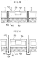
- Air purification has been acomplished by, for example, an air cleaning system such as the one shown in Figure 13 , which is composed of a plurality of filter units 100 , each of which is fixed on supporters 400 from a ceiling (not shown). Spacers 500 and caulking compounds 600 must be positioned in the space between the filter units 100 , making its installation complicated. The resulting sealing system is not enough to prevent a certain amount of air leakage.
- these units 100 may be installedon a ceiling by supporters 400 , each of which has a rectangular frame 101 .
- a gasket 601 such as a chloroprene sponge, is positioned between the filter frame 102 and the rectangular frame 101 , air leakage therefrom cannot be avoided. Furthermore even the airtight connection 105 between the air filter module 103 and the fan module 104 in each unit 100 cannot prevent all air leakage.
- the filter module 103 and the fan module 104 constituting the above-mentioned filter unit 100 are large and heavy, so that the filter unit 100 is correspondingly bulky and heavy as a whole thereby. Subsequently, the unit is noisy, difficult to install, inspect and repair. Replacement of parts such as the fan, filter, etc., are also difficult due to the size and weight.
- the thin lightweight air cleaner of this invention which overcomes the above-discussed disadvantages and other numerous drawbacks of the prior art, comprises a thin lightweight fan module having a fan, a casing containing said fan therein and a housing containing said casing therein; a thin lightweight air filter module having an air filter; and an air flow moderator disposed between said fan module and said air filter module.
- the casing is, in a preferred embodiment, eccentrically positioned within said housing of the fan module to create a large space in front of the outlet of said fan casing.
- the two each adjacent housings in which the fan casings face each other are, in a preferred embodiment, separated by a partition in such a manner that the end portion of the outlet of the casing in the housing is connected by said partition to the end portion of the outlet of the other casing, thereby regulating the direction of each of the air flows from said fan casings.
- the housing is, in a preferred embodiment, provided with vibration and noise absorbers.
- the fan is a propeller-type fan or a sirocco fan.
- the fan is, in a preferred embodiment, provided with a resonance prevention device at its back.
- the resonance prevention device is, in a preferred embodiment, a flywheel.
- the thin lightweight air cleaner system of this invention which overcomes the above-discussed disadvantages and other numerous drawbacks of the prior art, comprises
- the air filter module is thin and lightweight.
- the fan module is, likewise, thin and lightweight.
- the fan is a propeller-type fan or a sirocco fan.
- the housing is, in a preferred embodiment, provided with vibration and noise absorbers.
- the fan is, in a preferred embodiment, provided with a resonance prevention device at its back.
- the invention described herein makes possible the objects of (1) providing an air cleaner which has a high collection efficiency and an excellent ventilation ability; (2) providing a noiseless air cleaner; (3) providing an air cleaner, which is thin and lightweight; (4) providing an air cleaner which produces a uniform rate of air flow; (5) providing a small-sized air cleaner which can be installed in a small space; (6) providing an air cleaning system which is composed of the above-mentioned air cleaner and in which complete airtightness can be maintained; (7) providing an air cleaning system wherein the fan module and/or the filter module can be readily exchanged for another without damaging the airtightness between both modules; (8) providing an air cleaning system which is readily installed and repaired due to the use of a thin lightweight fan and filter modules; both of which are combined with each other by a simple sealing system; (9) providing an air cleaning system which can be readily subjected to inspection and/or maintenance because of its simple structure and simple sealing system; and (10) providing a system which is energysaving.
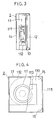
- FIGS 1 , 2 and 3 show an air cleaner 1 of this invention, which comprises a fan module 11 having a sirocco fan 111 , a casing 112 containing the fan 111 therein and a housing 114 containing the casing 112 therein; and an air filter module 12 having an air filter 121 .
- the thickness of the fan 111 i.e., the thickness of the fan module 11
- the filter 121 has a collection efficiency of 99.97 % with respect to dioctylphthalate particles of a size of 0.3 ⁇ m in a monodisperse system.
- An example of the filter 121 is an HEPA (High Efficiency Particulate Air) filter.
- the thickness of the filter module 12 containing such an HEPA filter is, for example, as thin as 100 mm or less, while that of a conventional filter module is 150 mm.
- a prefilter 14 can be positioned at the back of the fan 111 as desired.
- a guide vane 15 is positioned at each corner of the housing 114 to avoid turbulence from air discharged from the outlet 113 of the fan casing 112 as it collides with the wall 115 of the housing 114 , forming a turbulent flow.
- the guide vane 15 can be a plastic board, etc., but is not limited thereto.
- the air flow from the outlet 113 of the fan casing 112 is not uniform with respect to dynamic pressure thereof in the whole region of the outlet 113 , because the rate of the air flow within the circular duct within the casing 112 is greater along the inner diameter of the duct than along the outer diameter thereof. While the air flow, having an ununiform dynamic pressure, reaches the filter 121 , passing through the significantly long path between the fan casing 112 and the housing 114 , the dynamic pressure is gradually reduced to a static pressure.
- a moderator 13 such as a plastic board, etc. is positioned between the fan module 11 and the filter module 12 .
- the dynamic pressure is reduced to a static pressure.
- the air flow having a reduced dynamic pressure collides with the whole back face of the filter 121 and passes therethrough with a uniform distribution flow rate.
- Figure 4 shows another air cleaner 2 , in which the casing 112 of the fan 111 is eccentrically positioned within the housing 114 of the fan module 11 to create a large space 110 in front of the outlet 113 of the casing 112 .
- the casing 112 of the fan 111 is eccentrically positioned within the housing 114 of the fan module 11 to create a large space 110 in front of the outlet 113 of the casing 112 .
- its dynamic pressure is reduced forming a gentle flow, which, then, comes into the path between the moderator 13 and the filter module 12 to create an even more gently flow.
- thi significantly gentle air flow is fed into the back face of the filter 121 .
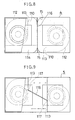
- FIGS 5 , 6 and 7 show another air cleaner 3 according to this invention, in which a pair of fan casings 112 are disposed facing each other with respect to their outlets 113 .
- Each of the fan casings 112 is positioned in each of the two adjacent housings 114 which are divided by a partition 116 serving to prevent an interference of the air flow from the outlets 113 of the fan casings 112 and create a low level of noise from the air cleaner 3 .
- the noise produced by the air cleaner 3 provided with the partition 116 according to this invention was 50 dB(A), while that from an air cleaner having no partition was as high as 55 dB(A).
- Guide vanes 15 which are positioned at the corner of the housing 114 , are effective to avoid an interference phenomenon deriving from the air discharged from the fan casings 112 .
- the partition 116 and the guide vane 15 may be made of plastics, etc., but are not limited thereto.
- This air cleaner 3 is also provided with a moderator 13 such as a plastic board, etc., which is positioned between the fan module 11 and the filter module 12 , resulting in the reduced dynamic pressure of the air flow from the fan 111 for the same reasons as in the above-mentioned cleaner 1 .
- a moderator 13 such as a plastic board, etc.
- each of the fan casings 112 may be eccentrically positioned within the housing 114 to create a large space 110 before the outlet 113 of the fan casing 112 , thereby allowing for the reduction of the dynamic pressure of the air flow from the outlet 113 of the fan casing 112 and resulting in a gentle flow having a static pressure. Then, the gentle flow comes into the path between the moderator 13 and the filter module 12 , becoming even more gentle, and the resulting significantly gentle flow collides uniformly with the whole face of the filter 121 and passes through the filter 121 .
- the partition 116 may be positioned in such a manner to connect the end portion 117 of the outlet 113 of the fan casing 112 to the end portion 117 of the outlet 113 of the other casing 112 .
- the air flow from each of the fans 111 reaches the filter 121 through a different path, that is, the air flow from the fan casing 112 is fed into the filter 121 , passing through the path around the other casing 112 .
- FIG. 10 and 11 Another air cleaner 6 according to this invention is shown in Figures 10 and 11 , which comprises a fan module 61 having a propeller-type fan 611 , a casing 612 of the fan 611 and a housing 614 containing the fan casing 612 therein, and an air filter module 62 having an air filter 621 .
- a moderator 63 is positioned between the fan module 61 and the filter module 62 .
- the space between the fan casing 612 and the housing 614 is partly or wholly filled with a vibration absorber and/or a noise absorber 66 made of a glass wool and/or a plastic foam such as a polyurethane foam, a polystyrene foam, etc. to reduce vibration and noise from the fan 611 .
- the fan 611 is a thin compact propeller fan, it can operate at a high speed, as compared with a conventional multiblade type-fan, thereby attaining a high ventilation efficiency and an excellent air-flow rate distribution.
- the filter 621 in this cleaner 6 is the same as that used in the above-mentioned cleaner 1 .
- a prefilter 64 may be positioned at the back of the fan casing 612 as desired.
- Regulators 65 made of an involute- or paraboloid-shaped aluminum or plastic board, etc. are disposed from around the outlet 613 of the casing 612 to the ends of the back of the filter module 62 , thereby preventing turbulence of the air flow from the outlet 613 of the fan casing 612 and guiding the air flow to the back of the filter 621 .
- the ventilation efficiency of the fan 611 and the uniform distribution of the flow rate of the air from the fan 611 to the filter 621 can be maintained at a high level. The occurance of noise can be also reduced.
- the moderator 63 between the fan module 61 and the filter module 62 serves to make the air-flow rate distribution more uniform.
- the moderator 63 is made of a porous plastic or aluminum board, etc. having a plurality of openings of a diameter of, for example, 2.5 mm comprising 30 % of the surface area of the filter. Upon passing through the moderator 63 , the air flow becomes streamlined as it flows downward.
- a thin-type diffuser can be used.
- the rotation number of each of the fans 611 varies according to a change in the voltage and/or loading thereby causing a rotation resonance which results in beats, vibrations and noise of the fan 611 .
- a resonance prevention device 67 such as a flywheel is mounted to the back of the fan 611 .
- the resonance prevention device 67 rotates together with the fan 611 , maintaining a stable rotation rate due to its inertia force so that surging due to noise interference can be reduced thereby attaining a decrease in a vibration and noise from the fan 611 .
- Figure 12 shows an air cleaning system 7 , which comprises (1) a latticework of interconnected H-shaped channels 70 having their openings 71 directed upwardly and a sealing liquid 72 positioned therein; (2) a plurality of air filter modules 62 each of which has a surrounding frame 73 containing a continuous U-shaped channel 74 , said U-shaped channel 74 having an upwardly directed opening 75 and a sealing liquid 72 positioned therein and said upwardly directed opening 75 of the U-shaped channel 74 receiving the lower rim 701 of said H-shaped channel 70 ; and (3) a plurality of fan modules 61 , each of which has a surrounding frame 68 containing a continuous vertically disposed extension 671 which rests in the upwardly directed opening 71 of the H-shaped channel 70 .
- This air cleaning system 7 further comprises a supporter 76, the end of which is connected to a portion such as a ceiling on which this cleaning system 7 should be installed and the other end of which is connected to a cover 77 by the use of a fastening means 78 such as a screw through the H-shaped channel 70 , thereby mounting this air cleaning system 7 horizontally on a ceiling, etc..
- the cover 77 also serves to keep the H-shaped channel 70 and the U-shaped channel 74 from sight.
- the fan module 61 is the same as that used in the air cleaner 6 shown in Figures 10 and 11 , or the fan module 11 which is used for the air cleaner 1 shown in Figure 1 .
- the filter module 62 maybe the same as that used in the air cleaner 1 shown in Figure 2 or the air cleaner 6 shown in Figure 11 .
- the H-shaped channel 70 , the surrounding frames 68 and 73 of the fan module 61 and the filter module 62 respectively, and the continuous U-shaped channel 74 all are made of a metal such as aluminum, iron, etc., or a venner or a synthetic resin, but are no limited thereto.
- the sealing liquid 72 positioned in the openings 71 and 75 is a non-volatile sealant, preferablly having excellent adhesiveness and a long pot life, examples of which are modified-urethane derivatives and silicon derivatives.
- a purified air can be created as follows:
- the discharged air from the fan casing 612 is fed into the porous moderator 63 without causing turbulence due to the regulator 65 .
- the dynamic pressure of the air flow is significantly reduced during passage through the porous moderator 63 , forming a streamlined downward flow which has a uniform distribution flow rate, when it reaches the back of the filter 621 .
- the air is cleaned by the filter 621 , attaining purified air in the room in which this cleaning system 7 is installed. Since the filter module 62 is also airtightly isolated from the outside by the H-shaped channel 70 , untreated air from the outside cannot come into the room.
- a non-porous board can be positioned between the fan module 61 and the filter module 62 .
- This air cleaning system 7 can be readily disassembled by loosing the fastening means 78 and removing in turn the cover 77 , the filter module 62 and the fan module 61 . After the removal of the filter module 62 , the fan module 61 can be subjected to inspection from inside the room.
Landscapes
- Chemical & Material Sciences (AREA)
- Engineering & Computer Science (AREA)
- Combustion & Propulsion (AREA)
- Mechanical Engineering (AREA)
- General Engineering & Computer Science (AREA)
- Chemical Kinetics & Catalysis (AREA)
- Filtering Of Dispersed Particles In Gases (AREA)
Priority Applications (1)
| Application Number | Priority Date | Filing Date | Title |
|---|---|---|---|
| EP89110273A EP0336455B1 (fr) | 1983-12-16 | 1984-12-14 | Epurateur d'air |
Applications Claiming Priority (9)
| Application Number | Priority Date | Filing Date | Title |
|---|---|---|---|
| JP23754583A JPS60129115A (ja) | 1983-12-16 | 1983-12-16 | 空気清浄装置 |
| JP237545/83 | 1983-12-16 | ||
| JP240565/83 | 1983-12-19 | ||
| JP24056583A JPS60132614A (ja) | 1983-12-19 | 1983-12-19 | 空気清浄装置 |
| JP65885/84 | 1984-05-04 | ||
| JP6588584U JPS60176226U (ja) | 1984-05-04 | 1984-05-04 | エアフイルタ−装置 |
| JP12232384A JPS61426A (ja) | 1984-06-14 | 1984-06-14 | 空気濾過装置 |
| JP122323/84 | 1984-06-14 | ||
| EP89110273A EP0336455B1 (fr) | 1983-12-16 | 1984-12-14 | Epurateur d'air |
Related Parent Applications (1)
| Application Number | Title | Priority Date | Filing Date |
|---|---|---|---|
| EP84308738.8 Division | 1984-12-14 |
Publications (3)
| Publication Number | Publication Date |
|---|---|
| EP0336455A2 true EP0336455A2 (fr) | 1989-10-11 |
| EP0336455A3 EP0336455A3 (en) | 1989-12-13 |
| EP0336455B1 EP0336455B1 (fr) | 1991-05-15 |
Family
ID=27513672
Family Applications (1)
| Application Number | Title | Priority Date | Filing Date |
|---|---|---|---|
| EP89110273A Expired EP0336455B1 (fr) | 1983-12-16 | 1984-12-14 | Epurateur d'air |
Country Status (1)
| Country | Link |
|---|---|
| EP (1) | EP0336455B1 (fr) |
Family Cites Families (3)
| Publication number | Priority date | Publication date | Assignee | Title |
|---|---|---|---|---|
| US3486311A (en) * | 1967-12-22 | 1969-12-30 | Flanders Filters | Filter bank assembly |
| DE2835104A1 (de) * | 1978-08-10 | 1980-02-21 | Seier Helmut Gmbh | Spannvorrichtung fuer eine filteranordnung |
| US4344784A (en) * | 1981-02-27 | 1982-08-17 | Dexon, Inc. | Filter assembly for clean air rooms and work stations |
-
1984
- 1984-12-14 EP EP89110273A patent/EP0336455B1/fr not_active Expired
Also Published As
| Publication number | Publication date |
|---|---|
| EP0336455A3 (en) | 1989-12-13 |
| EP0336455B1 (fr) | 1991-05-15 |
Similar Documents
| Publication | Publication Date | Title |
|---|---|---|
| US4790863A (en) | Air cleaner | |
| US5470363A (en) | Air blower and filter assemblies | |
| EP1019659B1 (fr) | Procede et appareil pour minimiser le bruit provenant d'une unite de filtrage a soufflerie | |
| US4427427A (en) | Vertical laminar flow filter module | |
| US4178159A (en) | Clean room filter assembly | |
| GB2157765A (en) | For use in clean air environments | |
| US6315525B1 (en) | Multi-purpose clean air fan and fan motor mount assembly | |
| US3465666A (en) | Cleanroom filtering method | |
| EP0510946A2 (fr) | Appareil d'alimentation en air | |
| EP0336455A2 (fr) | Epurateur d'air | |
| US20050092544A1 (en) | Fan unit air flow control | |
| JPH06281194A (ja) | 送風装置 | |
| CA2377819C (fr) | Systeme de filtration modulaire pour salle blanche | |
| JP3264553B2 (ja) | 送風装置 | |
| CN204943692U (zh) | 一种空气净化加湿器 | |
| KR0173766B1 (ko) | 국부청정실에 공급하는 정화된 난류량이 적은 공기흐름 발생장치 | |
| JP2564286B2 (ja) | 空気清浄装置 | |
| CN211837018U (zh) | 新型送风口 | |
| JP2000084326A (ja) | ケミカルフィルタと塵埃除去フィルタとを備えた空気清浄化装置とその利用設備 | |
| CN210535348U (zh) | 一种制氧站生产用降噪装置 | |
| JPS61426A (ja) | 空気濾過装置 | |
| RU27948U1 (ru) | Вентилятор-воздухоочиститель | |
| CN221036074U (zh) | 一种洁净室的送风装置 | |
| KR20210129518A (ko) | 클린룸용 공조필터박스 | |
| KR200151098Y1 (ko) | 장비 부착용 공기 청정장치 |
Legal Events
| Date | Code | Title | Description |
|---|---|---|---|
| PUAI | Public reference made under article 153(3) epc to a published international application that has entered the european phase |
Free format text: ORIGINAL CODE: 0009012 |
|
| 17P | Request for examination filed |
Effective date: 19890627 |
|
| AC | Divisional application: reference to earlier application |
Ref document number: 147143 Country of ref document: EP |
|
| AK | Designated contracting states |
Kind code of ref document: A2 Designated state(s): CH DE FR GB LI |
|
| PUAL | Search report despatched |
Free format text: ORIGINAL CODE: 0009013 |
|
| AK | Designated contracting states |
Kind code of ref document: A3 Designated state(s): CH DE FR GB LI |
|
| 17Q | First examination report despatched |
Effective date: 19900426 |
|
| GRAA | (expected) grant |
Free format text: ORIGINAL CODE: 0009210 |
|
| AC | Divisional application: reference to earlier application |
Ref document number: 147143 Country of ref document: EP |
|
| AK | Designated contracting states |
Kind code of ref document: B1 Designated state(s): CH DE FR GB LI |
|
| REF | Corresponds to: |
Ref document number: 3484603 Country of ref document: DE Date of ref document: 19910620 |
|
| ET | Fr: translation filed | ||
| PLBE | No opposition filed within time limit |
Free format text: ORIGINAL CODE: 0009261 |
|
| STAA | Information on the status of an ep patent application or granted ep patent |
Free format text: STATUS: NO OPPOSITION FILED WITHIN TIME LIMIT |
|
| 26N | No opposition filed | ||
| PGFP | Annual fee paid to national office [announced via postgrant information from national office to epo] |
Ref country code: GB Payment date: 19981201 Year of fee payment: 15 |
|
| PGFP | Annual fee paid to national office [announced via postgrant information from national office to epo] |
Ref country code: FR Payment date: 19981216 Year of fee payment: 15 Ref country code: CH Payment date: 19981216 Year of fee payment: 15 |
|
| PGFP | Annual fee paid to national office [announced via postgrant information from national office to epo] |
Ref country code: DE Payment date: 19981221 Year of fee payment: 15 |
|
| PG25 | Lapsed in a contracting state [announced via postgrant information from national office to epo] |
Ref country code: GB Free format text: LAPSE BECAUSE OF NON-PAYMENT OF DUE FEES Effective date: 19991214 |
|
| PG25 | Lapsed in a contracting state [announced via postgrant information from national office to epo] |
Ref country code: LI Free format text: LAPSE BECAUSE OF NON-PAYMENT OF DUE FEES Effective date: 19991231 Ref country code: CH Free format text: LAPSE BECAUSE OF NON-PAYMENT OF DUE FEES Effective date: 19991231 |
|
| GBPC | Gb: european patent ceased through non-payment of renewal fee |
Effective date: 19991214 |
|
| PG25 | Lapsed in a contracting state [announced via postgrant information from national office to epo] |
Ref country code: FR Free format text: LAPSE BECAUSE OF NON-PAYMENT OF DUE FEES Effective date: 20000831 |
|
| PG25 | Lapsed in a contracting state [announced via postgrant information from national office to epo] |
Ref country code: DE Free format text: LAPSE BECAUSE OF NON-PAYMENT OF DUE FEES Effective date: 20001003 |
|
| REG | Reference to a national code |
Ref country code: FR Ref legal event code: ST |