EP0510946A2 - Appareil d'alimentation en air - Google Patents
Appareil d'alimentation en air Download PDFInfo
- Publication number
- EP0510946A2 EP0510946A2 EP92303613A EP92303613A EP0510946A2 EP 0510946 A2 EP0510946 A2 EP 0510946A2 EP 92303613 A EP92303613 A EP 92303613A EP 92303613 A EP92303613 A EP 92303613A EP 0510946 A2 EP0510946 A2 EP 0510946A2
- Authority
- EP
- European Patent Office
- Prior art keywords
- air
- duct
- control unit
- flow
- supplying apparatus
- Prior art date
- Legal status (The legal status is an assumption and is not a legal conclusion. Google has not performed a legal analysis and makes no representation as to the accuracy of the status listed.)
- Ceased
Links
Images


Classifications
-
- F—MECHANICAL ENGINEERING; LIGHTING; HEATING; WEAPONS; BLASTING
- F24—HEATING; RANGES; VENTILATING
- F24F—AIR-CONDITIONING; AIR-HUMIDIFICATION; VENTILATION; USE OF AIR CURRENTS FOR SCREENING
- F24F13/00—Details common to, or for air-conditioning, air-humidification, ventilation or use of air currents for screening
- F24F13/02—Ducting arrangements
- F24F13/06—Outlets for directing or distributing air into rooms or spaces, e.g. ceiling air diffuser
- F24F13/068—Outlets for directing or distributing air into rooms or spaces, e.g. ceiling air diffuser formed as perforated walls, ceilings or floors
-
- F—MECHANICAL ENGINEERING; LIGHTING; HEATING; WEAPONS; BLASTING
- F24—HEATING; RANGES; VENTILATING
- F24F—AIR-CONDITIONING; AIR-HUMIDIFICATION; VENTILATION; USE OF AIR CURRENTS FOR SCREENING
- F24F7/00—Ventilation
- F24F7/04—Ventilation with ducting systems, e.g. by double walls; with natural circulation
- F24F7/06—Ventilation with ducting systems, e.g. by double walls; with natural circulation with forced air circulation, e.g. by fan positioning of a ventilator in or against a conduit
- F24F7/08—Ventilation with ducting systems, e.g. by double walls; with natural circulation with forced air circulation, e.g. by fan positioning of a ventilator in or against a conduit with separate ducts for supplied and exhausted air with provisions for reversal of the input and output systems
-
- F—MECHANICAL ENGINEERING; LIGHTING; HEATING; WEAPONS; BLASTING
- F24—HEATING; RANGES; VENTILATING
- F24F—AIR-CONDITIONING; AIR-HUMIDIFICATION; VENTILATION; USE OF AIR CURRENTS FOR SCREENING
- F24F3/00—Air-conditioning systems in which conditioned primary air is supplied from one or more central stations to distributing units in the rooms or spaces where it may receive secondary treatment; Apparatus specially designed for such systems
- F24F3/12—Air-conditioning systems in which conditioned primary air is supplied from one or more central stations to distributing units in the rooms or spaces where it may receive secondary treatment; Apparatus specially designed for such systems characterised by the treatment of the air otherwise than by heating and cooling
- F24F3/16—Air-conditioning systems in which conditioned primary air is supplied from one or more central stations to distributing units in the rooms or spaces where it may receive secondary treatment; Apparatus specially designed for such systems characterised by the treatment of the air otherwise than by heating and cooling by purification, e.g. by filtering; by sterilisation; by ozonisation
- F24F3/167—Clean rooms, i.e. enclosed spaces in which a uniform flow of filtered air is distributed
Definitions
- the present invention relates to air supplying apparatus which condition air in terms of cleanliness, temperature and humidity and which supply the controlled (conditioned) air into a room.
- Air supplying apparatus are used for the purpose of supplying clean air, or clean air with controlled temperature and humidity into rooms which are in need of such conditioned air.
- Rooms requiring conditioned air include, e.g., rooms in which semiconductors, electronic devices and precision devices are produced, rooms in which pharmaceutical products or foodstuffs are produced, hospital operating rooms, and so forth. (Such rooms will be generally referred to as "clean rooms”, hereafter).
- An air cleaning system which is one-type of such air supplying apparatus, has an air recirculating blow- erand a filter which are disposed outside a room, and air supply pipes installed in the ceiling wall and side walls of the room.
- the supply pipes have outlet openings which open in the surfaces of such walls, so that filtered air blown by the blower is supplied into the room through the outlet openings.
- This type of system can supply air over a wide area in the room at a sufficiently large flow rate, but requires much cost and labor to install the air supply pipes, which must be embedded in the ceiling and side walls of the room and which open through the inner surfaces of the ceiling and side walls.
- introduction of this system to a room of an existing building requires a long construction period, as well as a huge cost.
- An air cleaning unit has been known in which an air recirculating blower and a filter are assembled together in a casing which is provided at its top and bottom ends with a clean air discharge opening and a room air suction opening respectively. It is possible to clean the air in a room with such an air cleaning unit.
- This unit can supply clean air only to limited portions of the room, and is unable to recirculate air at a sufficiently large rate to clean an entire room. With such air cleaning units, therefore, it is not possible to clean the air in a room to a desired extent.
- Japanese Laid-Open Patent No. 59-44538 proposes an improved air cleaning unit which employs a columnar structure equipped with an air suction opening and an air recirculating blower.
- a duct of a specific cross-sectional shape is provided on the upper side of this columnar structure so as to extend along the lower surface of a ceiling.
- Air outlets are provided in the duct.
- a plurality of such air cleaning units are used in a room having a large volume. In this known air cleaning unit, however, no specific consideration has been given to the pattern of distribution of the air discharged from the air outlets.
- the cleaned air cannot be supplied uniformly over the entire area of the room, which undesirably results in local concentrations or thinning of the controlled air, causing the cleanliness of the air in the room to be locally degraded, or the temperature and/or humidity to be deviated from the target level at local regions in the room.
- This type of air cleaning unit also poses a problem in that a considerably high level of noise is generated during its operation from, for example, the motor and blades of the blower. Consequently, noise limits are often exceeded in rooms where silence must be kept, e.g., hospital operating rooms. This problem is serious particularly when a plurality of such air cleaning units are used to cover a large space in a large room having a large internal volume.
- an object of the present invention is to provide an air supplying apparatus which is capable of uniformly discharging air from its air outlets at a reduced level of noise as compared with known air cleaning systems or units.
- an air supplying apparatus comprising: an air control unit for discharging air conditioned to a desired state; and an air discharging duct connected to an air outlet of the air control unit so as to receive the conditioned air from the air control unit through an opening which opens in a direction different from the direction of flow ofairthrough the aircontrol unit, the airdischarge duct being formed from at least one perforated sheet having a multiplicity of air outlet apertures.
- Fig. 1 is a schematic illustration of an air supplying apparatus according to one embodiment of the present invention installed in a clean room 1
- the air supplying apparatus include an air control unit 3, and an air outlet duct 8 which is connected to extend in a direction different from the direction of the flow of air through the air control unit 3 and which distributes the cleaned air into the room 1. That is, in Fig. 1, air flows in the vertical direction through air control unit 3, while air flows in the horizontal direction through air outlet duct 8.
- the air control unit 3 includes an air inlet unit 21, a blower 4, a high-efficiency particulate air filter 5 capable of removing dust and other contaminants from the air, a cooler 9 for cooling the air, a heater 10 for heating the air and a humidifier 11 for controlling the humidity of the air.
- the various components can be operated with blower 4 individually or in combination.
- the air outlet duct 8 connected to the air control unit 3 is adapted to deflect the air flowing through the air control unit 3, such that the air flows, for example, in parallel with the ceiling 2 of the room.
- the portions of the air outlet duct 8 other than the portion contacting the ceiling 2 are made of one or more perforated sheets 6, e.g., one or more punched metal sheets, having a multiplicity of pores serving as air outlet apertures 7.
- the air outlet apparatus 7 are evenly distributed ove the entire surface of perforated sheet 6.
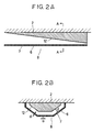
- the air outlet duct 8 has a cross-sectional shape similar to that of a ship's hull as shown in Fig. 2B and is elongated so as to extend along the ceiling as shown in Fig. 2A.
- the cross-sectional shape of air outlet duct 8 shown in Fig. 2B is only illustrative; the air outlet duct can have any other suitable cross-sectional shape such as, for example, a rectangular, semi-circular or inverse trapezoidal form, provided that the duct can uniformly supply air over as wide an -area as possible in the room.
- the cross-sectional area of the space inside air outlet duct 8, a which is available as the air passage, is progressively decreased from the upstream end region 13 (inlet) towards the downstream end region 14 as viewed in the direction of the flow of air.
- the cross-sectional area of the air outlet duct is progressively decreased from upstream end 13 towards downstream end 14 linearly or in a stepped manner.
- a flow passage adjusting member 12 can be installed in the air outlet duct so as to progressively decrease the cross-sectional area of the passage, as shown in Fig. 1 and 2A.
- the total head of the air in duct 8 which is the sum of the dynamic pressure v 2 /2 and the static pressure, is substantially equal over the entire region of the duct, and the rate of discharge of the air depends mainly on the static pressure in the duct.
- the static pressure is lower at the upstream side 13 where the flow velocity is large due to large air flow rate as compared with the downstream portion 14 where the flow velocity is small due to small air flow rate.
- a substantially equal flow velocity v of air is obtained both at the upstream portion 13 and the downstream portion 14, so that a substantially uniform static pressure and, hence, a substantially uniform distribution of air discharge rate can be obtained over the entire length of duct 8.
- the distance f of the clearance between the perforated plate 6 forming the duct 8 and the opposing surface of the flow passage adjusting member 12 is maintained substantially constant across each cross-sectional portion of duct 8, so that a substantially equal air discharge rate can be obtained in all directions at each cross-section of duct 8.
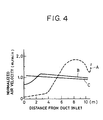
- Fig. 4 is a diagram showing the distribution of velocity of the air discharged from duct 8 in relation to the distance from the duct inlet, i.e., the upstream end 13 of duct 8.
- Curve A shows the flow velocity distribution as obtained when the cross-sectional area of the flow passage in the duct is constant over the entire length of duct 8
- curve B shows the flow velocity as observed when the cross-sectional area of the flow passage is progressively decreased towards the downstream end 14 of duct 8. It will be seen that the progressive reduction of the cross-sectional area of the flow passage greatly contributes to the realization of uniform distribution of air discharge rates.
- a test was conducted in which the time required for the air in the clean room 1 of Fig. 1 to be cleaned to a cleanliness degree of class 100 (Federal Standard 2090) was measured for both a duct having a constant cross-sectional area of the flow passage, and a duct having a progressively decreasing cross-sectional area of flow passage.
- the time required for cleaning to class 100 was measured to be 30 minutes when the duct having a constant cross-sectional area flow passage was used, and 10 minutes when the duct having a progressively decreasing cross-sectional area flow passage was used. It is thus possible to shorten the time required for cleaning the air in a room, by evenly distributing the cleaned air throughout the space in the room.
- Fig. 3A is a schematic side elevational view of the flow adjusting device 15, while Fig. 3B is a schematic overhead view of the same.
- the flow adjusting device 15 is disposed at the air inlet of duct 8 which is installed in the clean room 1 shown in Fig. 1.
- the flow adjusting device 15 includes vertical blades 16 and horizontal blades 17, both having an airfoil cross-section and being movably mounted so as to enable the direction of the flowing air to be adjusted both vertically and horizontally. Blades 16 and 17 are supported by respective shafts through friction. The level of friction is large enough to hold the blades in position against the pressure of the flowing air but is small enough to permit an easy rotation of the blades on the shafts by manual force.
- the user can adjust the directions of blades 16 and 17 so as to adjust the direction of the air entering duct 8, thereby minimizing local concentration of cleaned air in the clean room.
- a certain degree of offset or local concentration can occur in the flow of air emerging from filter 5 and entering duct 8.
- the flow velocity of air may not be uniform in a cross-sectional plane at the inlet of duct 8. Therefore, a nonuniform distribution of air discharge rate may be undesirably created in the inlet or upstream portion 13 of duct 8, as shown by the curve B in Fig. 4.
- This problem can be overcome by the provision of the flow adjusting device 15 which employs two types of blades 16, 17 for adjusting the flow of air both in the vertical and horizontal directions so as to develop a substantially uniform distribution of the air flow rate at the entrance of duct 8. It is therefore possible to obtain a substantially uniform distribution of air discharge rate in the upstream portion 13 of the duct 8.
- curve C shows the air discharge rate distribution as observed when both the flow passage adjusting member 12 and the flow adjusting device 15 are simultaneously used. It will be seen that a further uniform air discharge rate distribution is attained by the combined use of the flow passage adjusting member 12 (flow passage cross-section adjusting member) and the flow adjusting device 15 (flow direction adjusting device). Consequently, the cleaned air can be distributed throughout the space in the clean room with a greater degree of uniformity, thus offering a remarkable effect of cleaning air in the clean room.
- portions of the air outlet duct 8 other than the portion contacting ceiling 2 of the clean room are composed of one or more perforated sheets 6 (made from, for example, punched metal) each having a multiplicity of air outlet apertures 7.
- the diameter, a, of each air outlet aperture is determined in relation to the thickness, d, of the perforated sheet 6 so as to meet the condition of d/a a 1. This condition ensures that the flow of the air is stabilized in each outlet aperture 7 so as to enable the air to be discharged in the direction of the axis of each aperture (i.e., in Fig. 1 straight down).
- the diameter, a does not meet the above-described condition, i.e., when the condition is such that d/a ⁇ 1, the flow of air exiting from each aperture inevitably has a flow com- ponentdirected in the longitudinal direction of the duct 8. Consequently, the cleaned air discharged from outlet apertures 7 formed in the bottom wall of duct 8 are undesirably directed obliquely downward rather than being directed vertically, resulting in lack of uniformity in the distribution of the discharged air.
- the air supplying apparatus shown in Fig. 5 installed in a clean room, has an air control unit 3 for discharging air which has been controlled to a desired degree of cleanliness, temperature and humidity, a joint duct 18 which is connected to the outlet end of the air control unit 3 and an air outlet duct 8 which is connected to the downstream end of the joint duct 18.
- the joint duct 18 can be connected to any desired side of the air control unit 3, depending on the geometrical form and size of the room. When the clean room has a large internal volume, it is possible to use two of these apparatus, such that the two apparatus are disposed to oppose each other.
- the air flowing through the air control unit 3 is introduced into the joint duct 18, through an opening which opens in a direction different from the direction of flow of the air through the air control unit 3.
- the air then enters the air outlet duct 8 through an opening which opens in a direction different from the direction of flow of air through the joint duct 18.
- the air discharged from the air control unit 3 is repeatedly deflected as the air passes through the openings which are directed in different directions.
- the cross-sectional area of the air passage changes as the air flows from the air control unit 3 into the joint duct 18 and then into the outlet duct 8. Consequently, the noise energy propagating through the air is extinguished as a result of conversion from kinetic energy into thermal energy. Consequently, the level of noise is lowered each time the flow of air is deflected, whereby the noise level is lowered in the clean room.
- the second embodiment of the air supplying apparatus of the present invention includes an air control unit 3, a joint duct 18 connected to the outlet end of air control unit 3 and an air outlet duct 8 connected to the downstream end of joint duct 18.
- a tabular member 19 protrudes from a wall of joint duct 18 so as to project into the air passage.
- Tabular member 19 functions as a baffle plate which deflects air. Consequently, the air flowing through joint duct 18 experiences changes in the cross-sectional area of the flow passage, as well as flowing direction, so that the noise energy propagated through the flow of air is converted into Thermal energy, thus attaining a remarkable reduction in the noise level within the clean room.
- a further reduction in the noise level can be attained by lining the walls of the joint duct 18 with a sound absorbing material 20 which is, in this embodiment, an aluminum wool mat of about 25 mm thick.
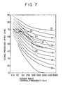
- Fig. 7 shows the measurements of sound pressure levels as measured at the center of a room at a level about 1.2 m above the floor surface, when the blower motor4 in the air control unit 3 was operated at a frequency of about 50 Hz.
- the measurement was conducted through octave band analysis.
- the abscissa represents the central frequency (Hz) of the octave band, while the ordinate axis represents the sound pressure level.
- a solid-line curve 22 shows the values measured with a conventional air supplying apparatus. In this case, peaks of sound pressure were observed at almost all central frequency bands. The maximum sound pressure level was 61dB (A). The NC value in the 125 Hz band exceeds 60.
- a chain-line curve 23 shows the sound pressure levels as observed with the air supplying apparatus of the invention incorporating the joint duct 18.
- a two- dot-and-dash line 24 shows the sound pressure levels as observed when the joint duct 19 is provided with the tabular member 19 serving as a baffle plate.
- a one-dot-and-dash line curve 25 indicates the sound pressure levels as observed when the joint duct 18 is equipped both with the tabular member 19 and the sound absorbing lining 20. It will be seen that the noise level in the clean room can be appreciably reduced by using the air supplying apparatus of the present invention.
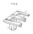
- Fig. 8 shows a modification of the air supplying apparatus in which three ducts 8 are connected to a single air control unit.
- any desired number of air discharge ducts e.g., two, four or more, may be connected to the air control unit 3.
- the number of air discharge ducts 8, as well as the directions in which these ducts extend, maybe determined in accordance with the shape of the room.
- an air outlet duct is connected to an air control unit so as to guide the air in a direction different from the direction of flow of the air through the air control unit.
- the cross-sectional area of the air passage defined in the air outlet duct is progressively reduced towards the downstream end of the air outlet duct.
- the duct is formed from one ore more perforated sheets having a multiplicity of air outlet apertures, the diameter of which is controlled in relation to the thickness of the perforated sheet.
- a joint duct is connected between the air control unit and the air outlet duct so as to realize a repeated change in the flowing direction of the cleaned air.
- the air supplying apparatus of the present invention can create a uniform distribution of cleaned air throughout a clean room, while reducing the level of the noise, as well as the cost required for installation.
Landscapes
- Engineering & Computer Science (AREA)
- Chemical & Material Sciences (AREA)
- Combustion & Propulsion (AREA)
- Mechanical Engineering (AREA)
- General Engineering & Computer Science (AREA)
- Ventilation (AREA)
- Air-Flow Control Members (AREA)
- Duct Arrangements (AREA)
Applications Claiming Priority (6)
| Application Number | Priority Date | Filing Date | Title |
|---|---|---|---|
| JP9190191 | 1991-04-23 | ||
| JP91901/91 | 1991-04-23 | ||
| JP298648/91 | 1991-11-14 | ||
| JP29864891 | 1991-11-14 | ||
| JP310586/91 | 1991-11-26 | ||
| JP3310586A JPH05141756A (ja) | 1991-11-26 | 1991-11-26 | 空気供給装置 |
Publications (2)
| Publication Number | Publication Date |
|---|---|
| EP0510946A2 true EP0510946A2 (fr) | 1992-10-28 |
| EP0510946A3 EP0510946A3 (en) | 1993-07-07 |
Family
ID=27306869
Family Applications (1)
| Application Number | Title | Priority Date | Filing Date |
|---|---|---|---|
| EP19920303613 Ceased EP0510946A3 (en) | 1991-04-23 | 1992-04-22 | Air supplying apparatus |
Country Status (4)
| Country | Link |
|---|---|
| US (1) | US5232401A (fr) |
| EP (1) | EP0510946A3 (fr) |
| KR (1) | KR920020145A (fr) |
| CA (1) | CA2066949A1 (fr) |
Cited By (1)
| Publication number | Priority date | Publication date | Assignee | Title |
|---|---|---|---|---|
| EP0899519B1 (fr) * | 1997-07-24 | 2000-05-17 | Marco Zambolin | Conduit de transport et de distribution d'air |
Families Citing this family (14)
| Publication number | Priority date | Publication date | Assignee | Title |
|---|---|---|---|---|
| JPH0926176A (ja) * | 1995-07-07 | 1997-01-28 | Canon Inc | 処理システムとこれを用いたデバイス生産方法 |
| US6632260B1 (en) | 1999-04-28 | 2003-10-14 | Stratotech Corporation | Adjustable clean-air flow environment |
| EP1258182A4 (fr) | 2000-02-18 | 2008-12-17 | Rtkl Associates Inc | Dispositif d'extraction de chaleur pour un bati d'ordinateur |
| US6557357B2 (en) | 2000-02-18 | 2003-05-06 | Toc Technology, Llc | Computer rack heat extraction device |
| US6412292B2 (en) | 2000-05-09 | 2002-07-02 | Toc Technology, Llc | Computer rack heat extraction device |
| US6574970B2 (en) | 2000-02-18 | 2003-06-10 | Toc Technology, Llc | Computer room air flow method and apparatus |
| FR2824626B1 (fr) * | 2001-05-14 | 2004-04-16 | Pierre Bridenne | Procede et dispositif pour diffuser un flux de protection a l'egard d'une ambiance environnante |
| US6668565B1 (en) | 2002-04-12 | 2003-12-30 | American Power Conversion | Rack-mounted equipment cooling |
| US7046514B2 (en) | 2003-03-19 | 2006-05-16 | American Power Conversion Corporation | Data center cooling |
| US6859366B2 (en) * | 2003-03-19 | 2005-02-22 | American Power Conversion | Data center cooling system |
| US7259963B2 (en) * | 2004-12-29 | 2007-08-21 | American Power Conversion Corp. | Rack height cooling |
| US7841199B2 (en) * | 2005-05-17 | 2010-11-30 | American Power Conversion Corporation | Cold aisle isolation |
| NL1037249C2 (nl) * | 2009-09-03 | 2011-03-08 | Qrisp B V | Inrichting en werkwijze voor het aan ten minste een te koelen locatie toevoeren van een gekoelde luchtstroom. |
| WO2021257945A1 (fr) * | 2020-06-18 | 2021-12-23 | Airdaptive Llc | Appareil, système et procédé permettant d'empêcher la propagation de contaminants atmosphériques |
Family Cites Families (17)
| Publication number | Priority date | Publication date | Assignee | Title |
|---|---|---|---|---|
| US2239508A (en) * | 1938-12-15 | 1941-04-22 | Burgess Battery Co | Air-distributing apparatus for ventilating systems |
| US3170385A (en) * | 1961-10-18 | 1965-02-23 | New Castle Products Inc | Air screen structure components and method of operation |
| DE1427897C3 (de) * | 1961-12-22 | 1975-03-20 | Hoestemberghe & Kluetsch Gmbh, 6630 Saarlouis | Kühlbett für vierkantiges Walzgut |
| US3251289A (en) * | 1963-04-10 | 1966-05-17 | Armstrong Cork Co | Wedge-shaped plenum chamber |
| US3332334A (en) * | 1965-08-09 | 1967-07-25 | Melzer Herman | Air curtain apparatus |
| US3387551A (en) * | 1966-07-22 | 1968-06-11 | Pittsburgh Plate Glass Co | Air curtain for observation window |
| GB1204594A (en) * | 1967-02-14 | 1970-09-09 | Karl Heinz Steigerwald | Device for ventilating or air-conditioning a room or cabin |
| US3719136A (en) * | 1970-09-21 | 1973-03-06 | Nat Defence | Method and means for providing a clean area |
| US3726203A (en) * | 1971-06-23 | 1973-04-10 | Svenska Flaektfabriken Ab | Device for maintenance of a dustfree, bacteria-free zone in a room |
| US3744724A (en) * | 1972-03-24 | 1973-07-10 | Sulzer Ag | Air distributing channel |
| FR2350556A1 (fr) * | 1976-05-04 | 1977-12-02 | Segic | Element prefabrique de ventilation et de climatisation |
| US4700688A (en) * | 1979-03-08 | 1987-10-20 | Cambridge Engineering, Inc. | Ventilating hood |
| JPS5944538A (ja) * | 1982-09-06 | 1984-03-13 | Shoji Hirayama | クリ−ンル−ム用クリ−ンユニツトおよびクリ−ンル−ムシステム |
| US4854224A (en) * | 1983-06-21 | 1989-08-08 | Shoji Hirayama | Air cleaning apparatus and construction of clean room with the same |
| US4738188A (en) * | 1984-02-25 | 1988-04-19 | Nishida Tekko Corporation | Room air circulating apparatus |
| DE3604422A1 (de) * | 1986-02-13 | 1987-08-20 | Kessler & Luch Gmbh | Vorrichtung zum saeubern kontaminierter oberflaechen mittels stroemender luft |
| DE4016078C1 (fr) * | 1990-02-23 | 1991-03-21 | Dieter 8035 Stockdorf De Hodeck |
-
1992
- 1992-04-20 US US07/871,109 patent/US5232401A/en not_active Expired - Fee Related
- 1992-04-22 EP EP19920303613 patent/EP0510946A3/en not_active Ceased
- 1992-04-23 CA CA002066949A patent/CA2066949A1/fr not_active Abandoned
- 1992-04-23 KR KR1019920006871A patent/KR920020145A/ko not_active Ceased
Cited By (1)
| Publication number | Priority date | Publication date | Assignee | Title |
|---|---|---|---|---|
| EP0899519B1 (fr) * | 1997-07-24 | 2000-05-17 | Marco Zambolin | Conduit de transport et de distribution d'air |
Also Published As
| Publication number | Publication date |
|---|---|
| US5232401A (en) | 1993-08-03 |
| EP0510946A3 (en) | 1993-07-07 |
| CA2066949A1 (fr) | 1992-10-24 |
| KR920020145A (ko) | 1992-11-20 |
Similar Documents
| Publication | Publication Date | Title |
|---|---|---|
| US5232401A (en) | Air supplying apparatus | |
| US10775074B2 (en) | Sound attenuating air handler panel apparatus and method | |
| US6290266B1 (en) | Suction elbow provided with built-in guide blades | |
| US6213867B1 (en) | Venturi type air distribution system | |
| US4316406A (en) | Flow-distributing device and an air-intake screen provided with such a device | |
| US5107687A (en) | Air conditioning system | |
| US5518451A (en) | Clean room system | |
| US5313803A (en) | Air conditioning system for human-occupied spaces | |
| US3367257A (en) | Air control for white room | |
| US3750839A (en) | Air distribution apparatus | |
| AU575448B2 (en) | Gaseous fluid distribution devices | |
| JPS6231258B2 (fr) | ||
| US6623353B1 (en) | Venturi type air distribution system | |
| US3059564A (en) | Low noise air distributor | |
| US3714884A (en) | Device for ventilation systems in spaces | |
| CN100436836C (zh) | 使鼓风机过滤器装置的噪音最小化的装置 | |
| JPH0666439A (ja) | クリーンルーム及びエアサプライユニット | |
| JP3907608B2 (ja) | フィルターユニット | |
| EP1398575B1 (fr) | Appareil pour minimiser le bruit provenant d'une unite de ventilateur | |
| EP1637815B1 (fr) | Dispositif d'alimentation en air | |
| JP4514860B2 (ja) | 床吹出し型空調設備 | |
| JPH0828920A (ja) | クリーンルーム用空気清浄化装置 | |
| EP0354949B1 (fr) | Unite de diffusion d'air | |
| JP3670825B2 (ja) | 空調用吹出しグリル | |
| US3361049A (en) | Elongated rotatable parallel double jet diffuser |
Legal Events
| Date | Code | Title | Description |
|---|---|---|---|
| PUAI | Public reference made under article 153(3) epc to a published international application that has entered the european phase |
Free format text: ORIGINAL CODE: 0009012 |
|
| AK | Designated contracting states |
Kind code of ref document: A2 Designated state(s): DE FR GB IT |
|
| PUAL | Search report despatched |
Free format text: ORIGINAL CODE: 0009013 |
|
| AK | Designated contracting states |
Kind code of ref document: A3 Designated state(s): DE FR GB IT |
|
| 17P | Request for examination filed |
Effective date: 19930823 |
|
| 17Q | First examination report despatched |
Effective date: 19940620 |
|
| GRAG | Despatch of communication of intention to grant |
Free format text: ORIGINAL CODE: EPIDOS AGRA |
|
| STAA | Information on the status of an ep patent application or granted ep patent |
Free format text: STATUS: THE APPLICATION HAS BEEN REFUSED |
|
| 18R | Application refused |
Effective date: 19960922 |