EP0336620A2 - Appareillage pour détruire les calcus - Google Patents
Appareillage pour détruire les calcus Download PDFInfo
- Publication number
- EP0336620A2 EP0336620A2 EP89302970A EP89302970A EP0336620A2 EP 0336620 A2 EP0336620 A2 EP 0336620A2 EP 89302970 A EP89302970 A EP 89302970A EP 89302970 A EP89302970 A EP 89302970A EP 0336620 A2 EP0336620 A2 EP 0336620A2
- Authority
- EP
- European Patent Office
- Prior art keywords
- destroying
- energy
- calculus
- generating
- period
- Prior art date
- Legal status (The legal status is an assumption and is not a legal conclusion. Google has not performed a legal analysis and makes no representation as to the accuracy of the status listed.)
- Granted
Links
Images

Classifications
-
- A—HUMAN NECESSITIES
- A61—MEDICAL OR VETERINARY SCIENCE; HYGIENE
- A61B—DIAGNOSIS; SURGERY; IDENTIFICATION
- A61B17/00—Surgical instruments, devices or methods
- A61B17/22—Implements for squeezing-off ulcers or the like on inner organs of the body; Implements for scraping-out cavities of body organs, e.g. bones; for invasive removal or destruction of calculus using mechanical vibrations; for removing obstructions in blood vessels, not otherwise provided for
- A61B17/225—Implements for squeezing-off ulcers or the like on inner organs of the body; Implements for scraping-out cavities of body organs, e.g. bones; for invasive removal or destruction of calculus using mechanical vibrations; for removing obstructions in blood vessels, not otherwise provided for for extracorporeal shock wave lithotripsy [ESWL], e.g. by using ultrasonic waves
-
- A—HUMAN NECESSITIES
- A61—MEDICAL OR VETERINARY SCIENCE; HYGIENE
- A61B—DIAGNOSIS; SURGERY; IDENTIFICATION
- A61B17/00—Surgical instruments, devices or methods
- A61B2017/00017—Electrical control of surgical instruments
- A61B2017/00137—Details of operation mode
- A61B2017/00154—Details of operation mode pulsed
- A61B2017/00172—Pulse trains, bursts, intermittent continuous operation
-
- A—HUMAN NECESSITIES
- A61—MEDICAL OR VETERINARY SCIENCE; HYGIENE
- A61B—DIAGNOSIS; SURGERY; IDENTIFICATION
- A61B17/00—Surgical instruments, devices or methods
- A61B2017/00681—Aspects not otherwise provided for
- A61B2017/00694—Aspects not otherwise provided for with means correcting for movement of or for synchronisation with the body
- A61B2017/00699—Aspects not otherwise provided for with means correcting for movement of or for synchronisation with the body correcting for movement caused by respiration, e.g. by triggering
-
- A—HUMAN NECESSITIES
- A63—SPORTS; GAMES; AMUSEMENTS
- A63F—CARD, BOARD, OR ROULETTE GAMES; INDOOR GAMES USING SMALL MOVING PLAYING BODIES; VIDEO GAMES; GAMES NOT OTHERWISE PROVIDED FOR
- A63F9/00—Games not otherwise provided for
- A63F9/001—Games or toys connected to, or combined with, other objects; Objects with a second use as a toy or game
- A63F2009/0049—Objects with a second use as toy or game
- A63F2009/0064—Items relating to health or medical instruments
Definitions
- the present invention relates to an apparatus for destroying calculuses of the type in which a calculus in a human body is disintegrated with the destroying energy externally applied.
- a known apparatus for destroying calculuses is com severelyposed of destroying energy generator for generating destroying energy such as focused shock wave and focused ultrasonic wave, and an image processor for detecting a calculus existing in a human body and executing an appropriate processing for the purpose of breaking the detected calculus.
- destroying energy generator for generating destroying energy such as focused shock wave and focused ultrasonic wave
- an image processor for detecting a calculus existing in a human body and executing an appropriate processing for the purpose of breaking the detected calculus.
- it searches and detects a calculus in a human body, positions a focal point of an destroying energy at the detected calculus, and emits the destroying energy to the calculus to disintegrate.
- the calculus can perfectly be disintegrated with the destroying energy of one time application. Normally the energy is repeatedly applied to the calculus. Meanwhile, the human body respires, causing a motion in the body.
- the focal point of the radiated energy is set at the calculus location, the calculus location, with quantsing of the motion, will displace from the focal point. Consequently, the radiation hits another part in the body, which is located off the affected part, calculus. This possibly hurts another part of the body.
- a measure for the above problem is disclosed in Japanese Patent Disclosure No. 63-158049.
- a period of an end portion in an expiration duration is detected. During this period, the affected part is little displaced from the focal point of the radiation as set.
- the expiration end period is used for the positioning of the focus of the radiation at the affected part, and the generation of drive pulses for radiating the destroying energy that repetitively appear at a preset rate (repetitive frequency).
- the calculus is disintegrated only during that period.
- the rate is, for example, 2Hz, viz., the destroying energy is radiated every 0.5 sec., a number of drive pulses that is required to disintegrate the calculus can be obtained during the expiration end period.
- the rate is lower than 2Hz, for example, 0.5Hz, that is, if the pulse is generated every 2 sec., a number of drive pulses generated during the expiration end period is insufficient for obtaining the radiated energy enough to disintegrate the calculus. It is assumed that a number of breathings is 12 per minutes, a time of one breathings is 5 sec., an expiration duration is 3 sec., and the expiration end period is 2 sec. In this instance, if the rate is 0.5Hz, an extreme case may occur in which all pulses required for integrating the calculus are not generated during the expiration end period of 2 sec. Particularly, when the start time point of the expiration end period is not coincident with a time point of generating the first drive pulse, a number of pulses occurring during that period is reduced.
- an object of the present invention is to provide an apparatus for destroying calculuses which is capable of effectively generating drive pulses for destroying energy within a predetermined period regardless of the preset rate for generating the drive pulses, and hence is free from the another-part hurting problem caused by the mishitting of the destroying energy.
- an apparatus for destroying calculuses comprising means for generating focused destroying energy, means for positioning a focus of the destroying energy at a location of calculus in a human body, means for detecting a radiation period of the destroying energy, means for generating a first drive pulse to drive the destroying energy radiation at a time point coincident with a start point of the radiation period, the first drive pulse generating means being coupled with the radiation period detecting means; and means for generating during the radiation period, a train of drive pulses to repeatedly generate destroying energy at a predetermined rate, succeeding to the generation of the first drive pulse.
- a first drive pulse is generated at a start point of a predetermined period, and succeedingly a train of pulses is generated within the same period.
- An effective number of drive pulses can be secured during the predetermined period regardless of the rate. Therefore, the problem that the destroying energy mishits another part located off the affected part, calculus and adversely affects there is successfully solved. Additionally, a speedy treatment can be realized.
- Fig. 1 shows an arrangement of an apparatus for destroying calculuses according to an embodiment of the present invention.
- an ellipsoidal reflector 3 is so arranged that its focus is positioned at a calculus 2 in a human body 1.
- charges stored in a discharge power source 4 are discharged through a spank gap 5 located at a first focus point of the ellipsoidal reflector 3.
- a shock wave energy generated there is reflected by the ellipsoidal reflector 3, and is projected to the calculus 2 as a second focus of the ellipsoidal reflector.
- the focus of the ellipsoidal reflector 3 is positioned at a location of the calculus 2 in the human body 1, while seeing a display screen of a display unit 7 which presents the information of the innards of the human body as detected by an X-ray detector 6.
- An X-ray tube 8 and the detector 6 are disposed oppositely with the human body 1 intervening therebetween.
- An operator moves the human body 1 while seeing the display, and when the calculus 2 is positioned at the center of the display, the human body 1 is fixed.
- the display unit 7 is so arranged that the center of the display screen indicates the second focus of the ellipsoidal reflector 3. Accordingly, when the center of the display coincides with the calculus displayed, the destroying energy is radiated toward the calculus, to destroy the calculus.
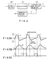
- An expiration end period detector 9 detects a expiration end period from a breathing period of the human body 1.
- a motion of the human body due to his breathing, viz., a movement of the calculus, is relatively small during the expiration end period. During this period, therefore, the positioning of the calculus to the focus is performed and the timing of generating an shock wave energy is decided, as already stated.
- a flow meter 100 measures a respiratory flow caused by a breathing, through a transducer (not shown) attached to a patient.
- a waveform of respiratory flow as denoted as A is illustrated in Fig. 3A.
- (+) indicates a variation of the inspiratory flow
- (-) indicates a variation of the expiratory flow.
- the result of respiratory flow measurement is supplied to a respiratory volumen calculator 101 which integrates the waveform A to obtain a waveform B representing an amount of respiratory volume in Fig. 3B.
- An expiration end period detector 102 compares a signal of the waveform B with a signal representative of a threshold value D (Fig. 3B), which is set by a threshold value setting circuit 103. A period that the waveform B is smaller than the threshold value D is produced in terms of an expiration period end signal C.
- An expiration end period in a breathing of a patient is detected by the expiration end period detector 9.
- the display unit 10 presents the expiration end period in the form of a periodic tone or an illumination to a patient.
- An operator positions a calculus of a patient at the second focus of the ellipsoidal reflector 3, viz, the center of a display screen of the display unit 7. This is done while he seeing an X-ray image on the display, and hearing the periodic tone or seeing the illuminating representing the expiration end period. The positioning thus obtained is correct during the expiration end period even when the calculus location is moved by his breathing.
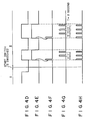
- a rate setting circuit 11 is first operated to set a frequency at 0.5Hz, for example. This figure indicates a low rate, and that shock wave energy is radiated every 2 sec. Then, a start switch 12 is switched over from position I to position II. Reference is made to Figs. 4D to 4H. At the position I, the enable terminal and clear terminal of a pulse generator 13, and the input terminal of a monostable multivibrator 14 are coupled with ground. In this state, the pulse generator 13 is free from the calculus disintegrating operation. When the switch 12 is turned to the position II manually or automatically, all the above terminals are connected to the expiration end period detector 9.
- the multivibrator 14 When a expiration end period (the positive portion of the waveform C in Fig. 3C) is detected, the multivibrator 14 generates a first pulse (F) as shown in Fig. 4F.
- This pulse (F) is applied as a first pulse of pulses (H) (Fig. 4H) to a controller 16, by way of an OR gate 15.
- the pulse generator 13 is enabled, to generate pulses (G) (Fig. 4G) recurring at the rate (0.5Hz, appearing every 2 sec.) as already set by the rate setting circuit 11.
- the pulses (G) also pass the OR gate 15 and, succeeding to the pulse (F), go in the form of the pulses (H) to the controller 16.
- the above operation is performed during the expiration end period.
- the pulse generator 13 When this period terminates, the pulse generator 13 is disabled, and a counter for the pulse outputting is also cleared, and waits for the next expiration end period.
- a possibly longest train of pulses (H) is applied at the set rate to the controller 16.
- the discharge power source 4 causes the discharge power source 4 to discharge the stored charges through the spark gap 5.
- the resultant shock wave energy is applied to the affected part, calculus, and disintegrates it.
- the operator confirms by using the display unit 7 that the calculus is disintegrated, and returns the switch 12 to the position I.
- the treatment operation by using the apparatus for destroying calculuses according to this invention ends.
- a combination of the monostable multivibrator 14, pulse generator 13, and OR gate 15 is used for forming the pulse train of the set rate. If required, a train of pulses appearing at the start point of the expiration end period may be formed by a combination of a microcomputer and a timer.
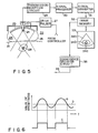
- an applicator 22 is used in contact with the surface of a human body 21.
- a disintegrating transducer 23 for breaking a calculus and imaging ultrasonic probe 24 for imaging the calculus are disposed as shown.
- the imaging ultrasonic probe 24 is located at the center of the disintegrating transducer 23.
- the applicator 22 is hermetically sealed by a membrane 25.
- the applicator 22 thus formed is filled with a liquid of an appropriate acoustic impedance, for example, water 26.
- the disintegrating transducer 23 is coupled with a drive pulser 27 by way of a cable.
- the drive pulser 27 is driven with a control signal derived from a controller (not shown), to radiate a focused ultrasonic energy into the human body 21.
- the imaging ultrasonic probe 24 is excited so as to make a sector scan, for example.
- An echo signal resulting from the sector scan is applied to a transmission/reception circuit 29.
- the output signal from the circuit 29 is applied to a signal processor 30 where it is amplitude detected.
- the detected signal is applied in the form of a digital video signal to a converting system 31.
- the output signal from the converting system 31 is temporarily stored in an image memory 32, and is applied to a TV monitor 33.
- the image memory 32 displays an acoustic domain image 34a in a sector fashion, an image 34b including a kidney, calculus, etc., and a focal marker 34c representing a focus of the ultrasonic energy transmitted from the disintegrating transducer 23.
- the sector image (B-mode image) 34a on the TV monitor presents a calculus in the human body.
- the calculus image has a high acoustic impedance, and therefore reflects the ultrasonic wave applied in a high intensity.
- the result is that the image 34a is brighter than its peripheral organic image.
- the focal marker 34c is fixed on the monitor screen. The reason for this is that the disintegrating transducer 23 and imaging ultrasonic probe 24 are fixedly disposed as shown. Therefore, to position the calculus image 34b at the focal marker 34, all one has to do is to move the applicator 22 so that both are coincident with each other in position.
- a coincidence decision circuit 35 works out a value of brightness of the acoustic domain image (B-mode image) contained in the focal marker 34c region, which is stored in the image memory 32, and outputs a coincidence-degree signal 36 every 5 sec., for example. More exactly, the coincident decision circuit 35 searches value of brightness B in excess of a predetermined value of brightness D and produces the values B in the form of the coincidence degree signal C. The duration of the signal C is used as the expiration end period. During this period, the disintegrating transducer is allowed to radiate the ultrasonic wave toward the calculus. The ultrasonic wave radiated, therefore, exactly hits the affected part, without hurting the tissue near the calculus in the human body.
Landscapes
- Health & Medical Sciences (AREA)
- Surgery (AREA)
- Life Sciences & Earth Sciences (AREA)
- Heart & Thoracic Surgery (AREA)
- Nuclear Medicine, Radiotherapy & Molecular Imaging (AREA)
- Vascular Medicine (AREA)
- Engineering & Computer Science (AREA)
- Biomedical Technology (AREA)
- Orthopedic Medicine & Surgery (AREA)
- Medical Informatics (AREA)
- Molecular Biology (AREA)
- Animal Behavior & Ethology (AREA)
- General Health & Medical Sciences (AREA)
- Public Health (AREA)
- Veterinary Medicine (AREA)
- Surgical Instruments (AREA)
Applications Claiming Priority (2)
| Application Number | Priority Date | Filing Date | Title |
|---|---|---|---|
| JP63076096A JPH01250240A (ja) | 1988-03-31 | 1988-03-31 | 結石破砕装置 |
| JP76096/88 | 1988-03-31 |
Publications (3)
| Publication Number | Publication Date |
|---|---|
| EP0336620A2 true EP0336620A2 (fr) | 1989-10-11 |
| EP0336620A3 EP0336620A3 (en) | 1990-04-25 |
| EP0336620B1 EP0336620B1 (fr) | 1993-12-29 |
Family
ID=13595322
Family Applications (1)
| Application Number | Title | Priority Date | Filing Date |
|---|---|---|---|
| EP89302970A Expired - Lifetime EP0336620B1 (fr) | 1988-03-31 | 1989-03-23 | Appareillage pour détruire les calcus |
Country Status (4)
| Country | Link |
|---|---|
| US (1) | US5054469A (fr) |
| EP (1) | EP0336620B1 (fr) |
| JP (1) | JPH01250240A (fr) |
| DE (1) | DE68911724T2 (fr) |
Cited By (11)
| Publication number | Priority date | Publication date | Assignee | Title |
|---|---|---|---|---|
| WO1999043260A1 (fr) * | 1998-02-25 | 1999-09-02 | St. Jude Children's Research Hospital | Moyen de modulation sensible a la respiration et appareil et procedes utilisant ce systeme |
| US7077820B1 (en) | 2002-10-21 | 2006-07-18 | Advanced Medical Optics, Inc. | Enhanced microburst ultrasonic power delivery system and method |
| US7169123B2 (en) | 1997-01-22 | 2007-01-30 | Advanced Medical Optics, Inc. | Control of pulse duty cycle based upon footswitch displacement |
| US7316664B2 (en) | 2002-10-21 | 2008-01-08 | Advanced Medical Optics, Inc. | Modulated pulsed ultrasonic power delivery system and method |
| US7485106B2 (en) | 1997-01-22 | 2009-02-03 | Advanced Medical Optics, Inc. | Micro-burst ultrasonic power delivery |
| CN1891170B (zh) * | 2005-07-04 | 2010-08-11 | 西门子公司 | 冲击波系统 |
| US7785336B2 (en) | 2006-08-01 | 2010-08-31 | Abbott Medical Optics Inc. | Vacuum sense control for phaco pulse shaping |
| US7846126B2 (en) | 2003-07-14 | 2010-12-07 | Abbott Medical Optics, Inc. | System and method for modulated surgical procedure irrigation and aspiration |
| US8945162B2 (en) | 2002-10-21 | 2015-02-03 | Abbott Medical Optics Inc. | System and method for pulsed ultrasonic power delivery employing cavitational effects |
| US9050627B2 (en) | 2011-09-02 | 2015-06-09 | Abbott Medical Optics Inc. | Systems and methods for ultrasonic power measurement and control of phacoemulsification systems |
| US11877953B2 (en) | 2019-12-26 | 2024-01-23 | Johnson & Johnson Surgical Vision, Inc. | Phacoemulsification apparatus |
Families Citing this family (4)
| Publication number | Priority date | Publication date | Assignee | Title |
|---|---|---|---|---|
| SE465600B (sv) * | 1989-03-21 | 1991-10-07 | Hans Wiksell | Trigganordning foer utloesande av chockvaag |
| DE4241161C2 (de) * | 1992-12-07 | 1995-04-13 | Siemens Ag | Akustische Therapieeinrichtung |
| JP5032226B2 (ja) * | 2007-07-05 | 2012-09-26 | 株式会社東芝 | 超音波治療装置 |
| CN113081244B (zh) * | 2021-05-14 | 2023-10-20 | 邦士医疗科技股份有限公司 | 一种体内结石粉碎仪 |
Family Cites Families (10)
| Publication number | Priority date | Publication date | Assignee | Title |
|---|---|---|---|---|
| US3735755A (en) * | 1971-06-28 | 1973-05-29 | Interscience Research Inst | Noninvasive surgery method and apparatus |
| US4315514A (en) * | 1980-05-08 | 1982-02-16 | William Drewes | Method and apparatus for selective cell destruction |
| US4368410A (en) * | 1980-10-14 | 1983-01-11 | Dynawave Corporation | Ultrasound therapy device |
| DE3146628C2 (de) * | 1981-11-25 | 1991-03-28 | Dornier System Gmbh, 7990 Friedrichshafen | Auslösevorrichtung für Stoßwellen zu therapeutischen Zwecken |
| US4620546A (en) * | 1984-06-30 | 1986-11-04 | Kabushiki Kaisha Toshiba | Ultrasound hyperthermia apparatus |
| JPS61209643A (ja) * | 1985-03-15 | 1986-09-17 | 株式会社東芝 | 超音波診断治療装置 |
| US4763652A (en) * | 1986-04-16 | 1988-08-16 | Northgate Research, Inc. | Aiming system for kidney stone disintegrator |
| EP0244730B1 (fr) * | 1986-05-09 | 1990-07-04 | Siemens Aktiengesellschaft | Dispositif destiné à la désintégration de concréments présents dans le corps d'un être vivant |
| US4803995A (en) * | 1986-06-27 | 1989-02-14 | Kabushiki Kaisha Toshiba | Ultrasonic lithotrity apparatus |
| DE3621935C2 (de) * | 1986-06-30 | 1996-12-12 | Siemens Ag | Lithotripter mit einer körperfunktionsgesteuerten Auslöseeinrichtung |
-
1988
- 1988-03-31 JP JP63076096A patent/JPH01250240A/ja active Pending
-
1989
- 1989-03-23 EP EP89302970A patent/EP0336620B1/fr not_active Expired - Lifetime
- 1989-03-23 US US07/327,821 patent/US5054469A/en not_active Expired - Lifetime
- 1989-03-23 DE DE89302970T patent/DE68911724T2/de not_active Expired - Fee Related
Cited By (25)
| Publication number | Priority date | Publication date | Assignee | Title |
|---|---|---|---|---|
| US9788998B2 (en) | 1997-01-22 | 2017-10-17 | Abbott Medical Optics Inc. | Control of pulse duty cycle based upon footswitch displacement |
| US8876747B2 (en) | 1997-01-22 | 2014-11-04 | Abbott Medical Optics Inc. | Micro-burst ultrasonic power delivery |
| US7169123B2 (en) | 1997-01-22 | 2007-01-30 | Advanced Medical Optics, Inc. | Control of pulse duty cycle based upon footswitch displacement |
| US7485106B2 (en) | 1997-01-22 | 2009-02-03 | Advanced Medical Optics, Inc. | Micro-burst ultrasonic power delivery |
| US8195286B2 (en) | 1997-01-22 | 2012-06-05 | Abbott Medical Optics Inc. | Control of pulse duty cycle based upon footswitch displacement |
| US6298260B1 (en) | 1998-02-25 | 2001-10-02 | St. Jude Children's Research Hospital | Respiration responsive gating means and apparatus and methods using the same |
| WO1999043260A1 (fr) * | 1998-02-25 | 1999-09-02 | St. Jude Children's Research Hospital | Moyen de modulation sensible a la respiration et appareil et procedes utilisant ce systeme |
| US7316664B2 (en) | 2002-10-21 | 2008-01-08 | Advanced Medical Optics, Inc. | Modulated pulsed ultrasonic power delivery system and method |
| US10245179B2 (en) | 2002-10-21 | 2019-04-02 | Johnson & Johnson Surgical Vision, Inc. | System and method for pulsed ultrasonic power delivery employing cavitation effects |
| US9707127B2 (en) | 2002-10-21 | 2017-07-18 | Abbott Medical Optics Inc. | Modulated pulsed ultrasonic power delivery system and method |
| US10765557B2 (en) | 2002-10-21 | 2020-09-08 | Johnson & Johnson Surgical Vision, Inc. | Modulated pulsed ultrasonic power delivery system and method |
| US9642745B2 (en) | 2002-10-21 | 2017-05-09 | Abbott Medical Optics Inc. | Modulated pulsed ultrasonic power delivery system and method |
| US8852138B2 (en) | 2002-10-21 | 2014-10-07 | Abbott Medical Optics Inc. | Modulated pulsed ultrasound power delivery system and method |
| US7077820B1 (en) | 2002-10-21 | 2006-07-18 | Advanced Medical Optics, Inc. | Enhanced microburst ultrasonic power delivery system and method |
| US8887735B2 (en) | 2002-10-21 | 2014-11-18 | Abbott Medical Optics Inc. | Modulated pulsed ultrasonic power delivery system and method |
| US8945162B2 (en) | 2002-10-21 | 2015-02-03 | Abbott Medical Optics Inc. | System and method for pulsed ultrasonic power delivery employing cavitational effects |
| US9545334B2 (en) | 2003-07-14 | 2017-01-17 | Abbott Medical Optics, Inc. | System and method for modulated surgical procedure irrigation and aspiration |
| US8814821B2 (en) | 2003-07-14 | 2014-08-26 | Abbott Medical Optics Inc. | System and method for modulated surgical procedure irrigation and aspiration |
| US7846126B2 (en) | 2003-07-14 | 2010-12-07 | Abbott Medical Optics, Inc. | System and method for modulated surgical procedure irrigation and aspiration |
| CN1891170B (zh) * | 2005-07-04 | 2010-08-11 | 西门子公司 | 冲击波系统 |
| US9226849B2 (en) | 2006-08-01 | 2016-01-05 | Abbott Medical Optics Inc. | Vacuum sense control for phaco pulse shaping |
| US8034067B2 (en) * | 2006-08-01 | 2011-10-11 | Abbott Medical Optics Inc. | Vacuum sense control for phaco pulse shaping |
| US7785336B2 (en) | 2006-08-01 | 2010-08-31 | Abbott Medical Optics Inc. | Vacuum sense control for phaco pulse shaping |
| US9050627B2 (en) | 2011-09-02 | 2015-06-09 | Abbott Medical Optics Inc. | Systems and methods for ultrasonic power measurement and control of phacoemulsification systems |
| US11877953B2 (en) | 2019-12-26 | 2024-01-23 | Johnson & Johnson Surgical Vision, Inc. | Phacoemulsification apparatus |
Also Published As
| Publication number | Publication date |
|---|---|
| EP0336620B1 (fr) | 1993-12-29 |
| DE68911724D1 (de) | 1994-02-10 |
| JPH01250240A (ja) | 1989-10-05 |
| DE68911724T2 (de) | 1994-04-28 |
| EP0336620A3 (en) | 1990-04-25 |
| US5054469A (en) | 1991-10-08 |
Similar Documents
| Publication | Publication Date | Title |
|---|---|---|
| EP0336620B1 (fr) | Appareillage pour détruire les calcus | |
| US5448994A (en) | Apparatus for performing medical treatment by using electroacoustic transducer element | |
| US5358466A (en) | Apparatus for destroying a calculus | |
| US4962754A (en) | Shock wave treatment apparatus | |
| US5311869A (en) | Method and apparatus for ultrasonic wave treatment in which medical progress may be evaluated | |
| EP0734742A3 (fr) | Appareillage à ultrasons thérapeutique | |
| EP0377901A1 (fr) | Appareil de traitement par ondes de choc | |
| US5005580A (en) | Destroying wave treatment apparatus | |
| EP0391378A2 (fr) | Appareil de lithotripsie à ondes de chocs utilisant des ondes ultrasoniques | |
| JPH02104343A (ja) | 超音波治療装置 | |
| JP2950582B2 (ja) | 結石破砕装置 | |
| US20040186397A1 (en) | Lithotripsy apparatus with an electromagnetic shockwave source triggered by evaluation of an ultrasound B-image | |
| JP3145084B2 (ja) | 超音波治療装置 | |
| JPS63288148A (ja) | 超音波治療装置 | |
| JP3015440B2 (ja) | 衝撃波治療装置及び温熱治療装置 | |
| JP3142535B2 (ja) | 超音波治療装置 | |
| JPH06189973A (ja) | 結石破砕装置 | |
| JP2850415B2 (ja) | 結石破砕装置 | |
| JPH01299545A (ja) | 衝撃波治療装置 | |
| JP2530019B2 (ja) | 衝撃波治療装置 | |
| JPS63158049A (ja) | 結石破砕装置 | |
| JPH0438944A (ja) | 衝撃波治療装置及び温熱治療装置 | |
| JPH02140154A (ja) | 衝撃波治療装置 | |
| JPH0710262B2 (ja) | 超音波治療装置 | |
| JP2002045365A (ja) | 超音波治療装置 |
Legal Events
| Date | Code | Title | Description |
|---|---|---|---|
| PUAI | Public reference made under article 153(3) epc to a published international application that has entered the european phase |
Free format text: ORIGINAL CODE: 0009012 |
|
| 17P | Request for examination filed |
Effective date: 19890412 |
|
| AK | Designated contracting states |
Kind code of ref document: A2 Designated state(s): DE FR |
|
| PUAL | Search report despatched |
Free format text: ORIGINAL CODE: 0009013 |
|
| AK | Designated contracting states |
Kind code of ref document: A3 Designated state(s): DE FR |
|
| 17Q | First examination report despatched |
Effective date: 19920616 |
|
| GRAA | (expected) grant |
Free format text: ORIGINAL CODE: 0009210 |
|
| AK | Designated contracting states |
Kind code of ref document: B1 Designated state(s): DE FR |
|
| REF | Corresponds to: |
Ref document number: 68911724 Country of ref document: DE Date of ref document: 19940210 |
|
| ET | Fr: translation filed | ||
| PLBE | No opposition filed within time limit |
Free format text: ORIGINAL CODE: 0009261 |
|
| STAA | Information on the status of an ep patent application or granted ep patent |
Free format text: STATUS: NO OPPOSITION FILED WITHIN TIME LIMIT |
|
| 26N | No opposition filed | ||
| PGFP | Annual fee paid to national office [announced via postgrant information from national office to epo] |
Ref country code: DE Payment date: 19991231 Year of fee payment: 12 |
|
| PG25 | Lapsed in a contracting state [announced via postgrant information from national office to epo] |
Ref country code: DE Free format text: LAPSE BECAUSE OF NON-PAYMENT OF DUE FEES Effective date: 20020101 |
|
| PGFP | Annual fee paid to national office [announced via postgrant information from national office to epo] |
Ref country code: FR Payment date: 20080311 Year of fee payment: 20 |