EP0336627A2 - Elastisches Lager - Google Patents
Elastisches Lager Download PDFInfo
- Publication number
- EP0336627A2 EP0336627A2 EP89303035A EP89303035A EP0336627A2 EP 0336627 A2 EP0336627 A2 EP 0336627A2 EP 89303035 A EP89303035 A EP 89303035A EP 89303035 A EP89303035 A EP 89303035A EP 0336627 A2 EP0336627 A2 EP 0336627A2
- Authority
- EP
- European Patent Office
- Prior art keywords
- tubular body
- resilient mounting
- elastomeric material
- buffer member
- buffer
- Prior art date
- Legal status (The legal status is an assumption and is not a legal conclusion. Google has not performed a legal analysis and makes no representation as to the accuracy of the status listed.)
- Granted
Links
Images

Classifications
-
- F—MECHANICAL ENGINEERING; LIGHTING; HEATING; WEAPONS; BLASTING
- F16—ENGINEERING ELEMENTS AND UNITS; GENERAL MEASURES FOR PRODUCING AND MAINTAINING EFFECTIVE FUNCTIONING OF MACHINES OR INSTALLATIONS; THERMAL INSULATION IN GENERAL
- F16F—SPRINGS; SHOCK-ABSORBERS; MEANS FOR DAMPING VIBRATION
- F16F1/00—Springs
- F16F1/36—Springs made of rubber or other material having high internal friction, e.g. thermoplastic elastomers
- F16F1/371—Springs made of rubber or other material having high internal friction, e.g. thermoplastic elastomers characterised by inserts or auxiliary extension or exterior elements, e.g. for rigidification
-
- B—PERFORMING OPERATIONS; TRANSPORTING
- B60—VEHICLES IN GENERAL
- B60K—ARRANGEMENT OR MOUNTING OF PROPULSION UNITS OR OF TRANSMISSIONS IN VEHICLES; ARRANGEMENT OR MOUNTING OF PLURAL DIVERSE PRIME-MOVERS IN VEHICLES; AUXILIARY DRIVES FOR VEHICLES; INSTRUMENTATION OR DASHBOARDS FOR VEHICLES; ARRANGEMENTS IN CONNECTION WITH COOLING, AIR INTAKE, GAS EXHAUST OR FUEL SUPPLY OF PROPULSION UNITS IN VEHICLES
- B60K5/00—Arrangement or mounting of internal-combustion or jet-propulsion units
- B60K5/12—Arrangement of engine supports
- B60K5/1291—Supports comprising stoppers
-
- F—MECHANICAL ENGINEERING; LIGHTING; HEATING; WEAPONS; BLASTING
- F16—ENGINEERING ELEMENTS AND UNITS; GENERAL MEASURES FOR PRODUCING AND MAINTAINING EFFECTIVE FUNCTIONING OF MACHINES OR INSTALLATIONS; THERMAL INSULATION IN GENERAL
- F16F—SPRINGS; SHOCK-ABSORBERS; MEANS FOR DAMPING VIBRATION
- F16F1/00—Springs
- F16F1/36—Springs made of rubber or other material having high internal friction, e.g. thermoplastic elastomers
- F16F1/42—Springs made of rubber or other material having high internal friction, e.g. thermoplastic elastomers characterised by the mode of stressing
- F16F1/52—Springs made of rubber or other material having high internal friction, e.g. thermoplastic elastomers characterised by the mode of stressing loaded in combined stresses
- F16F1/54—Springs made of rubber or other material having high internal friction, e.g. thermoplastic elastomers characterised by the mode of stressing loaded in combined stresses loaded in compression and shear
-
- B—PERFORMING OPERATIONS; TRANSPORTING
- B60—VEHICLES IN GENERAL
- B60G—VEHICLE SUSPENSION ARRANGEMENTS
- B60G2202/00—Indexing codes relating to the type of spring, damper or actuator
- B60G2202/10—Type of spring
- B60G2202/14—Plastic spring, e.g. rubber
- B60G2202/143—Plastic spring, e.g. rubber subjected to compression
-
- B—PERFORMING OPERATIONS; TRANSPORTING
- B60—VEHICLES IN GENERAL
- B60G—VEHICLE SUSPENSION ARRANGEMENTS
- B60G2204/00—Indexing codes related to suspensions per se or to auxiliary parts
- B60G2204/10—Mounting of suspension elements
- B60G2204/12—Mounting of springs or dampers
- B60G2204/125—Mounting of rubber type springs
-
- B—PERFORMING OPERATIONS; TRANSPORTING
- B60—VEHICLES IN GENERAL
- B60G—VEHICLE SUSPENSION ARRANGEMENTS
- B60G2204/00—Indexing codes related to suspensions per se or to auxiliary parts
- B60G2204/40—Auxiliary suspension parts; Adjustment of suspensions
- B60G2204/45—Stops limiting travel
- B60G2204/4504—Stops limiting travel using cable or band to prevent extension
-
- F—MECHANICAL ENGINEERING; LIGHTING; HEATING; WEAPONS; BLASTING
- F16—ENGINEERING ELEMENTS AND UNITS; GENERAL MEASURES FOR PRODUCING AND MAINTAINING EFFECTIVE FUNCTIONING OF MACHINES OR INSTALLATIONS; THERMAL INSULATION IN GENERAL
- F16F—SPRINGS; SHOCK-ABSORBERS; MEANS FOR DAMPING VIBRATION
- F16F2236/00—Mode of stressing of basic spring or damper elements or devices incorporating such elements
- F16F2236/12—Mode of stressing of basic spring or damper elements or devices incorporating such elements loaded in combined stresses
- F16F2236/123—Mode of stressing of basic spring or damper elements or devices incorporating such elements loaded in combined stresses loaded in compression and shear
Definitions
- This invention relates to a resilient mounting and to an assembly of two components resiliently interconnected by the resilient mounting of the invention.
- the invention is directed in particular, though not exclusively, to a resilient mounting able to withstand high compression load with low deflection in a first, longitudinal direction and to exhibit a relatively low stiffness in a second, transverse direction perpendicular to said first direction.
- the mounting is orientated with the first, longitudinal direction lying vertically and with the second, transverse direction therefore lying horizontally.
- the present invention provides a resilient mounting comprising a resilient component comprising a substantially tubular body of elastomeric material located between and bonded to generally planar confronting surfaces of a pair of end members, said body of elastomeric material being reinforced by an embedded annular reinforcement element of generally planar form arranged to lie between and substantially parallel with said confronting surfaces of the end members, a buffer member located within the internal cavity defined by the tubular body and secured to one of said end members, and a layer of elastomeric material provided between at least the reinforcement element and buffer member to prevent direct contact between said element and member when the mounting is subject to transverse load.
- the elastomeric material of the tubular body may extend over the inner edge of the annular reinforcement element, and if an end member is also of annular form the elastomeric material may extend over the inner edge of that member.
- the elastomeric material therefore is able to act as a cushion layer and prevent the buffer member provided within the internal cavity of the tubular body from coming into direct contact with the reinforcement element or an annular end member when the mounting is subjected to transverse loading.
- a layer of elastomeric material is provided to prevent direct contact between the buffer member and annular reinforcement element. If the buffer member extends through an annular end member in an arrangement in which it is normally spaced therefrom in the absence of applied load, a layer of elastomeric material, which may be the same as a layer between the buffer member and reinforcement element, may be provided to prevent direct contact between the buffer member and end member.
- Said layer of elastomeric material may be comprised by a sleeve of elastomeric material carried by the buffer member but preferably it is comprised by the elastomeric material of the tubular body arranged to extend over an inner edge of the reinforcement member and/or an annular end member.
- the buffer member may be comprised by attachment means, such as a bolt, provided for example for attachment of one of the end members to one of two components to be interconnected by the resilient mounting of the present invention.
- the attachment means is comprised by a bolt of stepped diameter, a first portion of larger diameter being arranged in the internal cavity and a second portion of reduced diameter extending through a central aperture in one of the end members and being screw-threaded over part of its length to facilitate attachment to one of two components to be interconnected.
- An annular shoulder defined by a step in diameter between the first and second portions may be arranged to engage the periphery of the central aperture in said one of the end members whereby said end member may be clamped to said one of the two components by the attachment means.
- the attachment means may be comprised by an essentially equivalent arrangement of, say, a conventional bolt of substantially uniform diameter surrounded over part of its length by a rigid sleeve.
- the other of the end members also may be apertured so that the bolt or other attachment means may extend therethrough with a head portion lying outside the internal cavity.
- an inner face of the head portion may be used to act as an axial stop to limit axial extension of the resilient mounting in said first direction.
- the inner face of the head portion may confront the other of said end members or one of the interconnected components; one of the confronting surfaces of the head portion and end member or interconnected component may be provided with a cushion layer of elastomeric material to prevent direct contact of said confronting surfaces.
- the tubular body of elastomeric material may be provided with more than one embedded reinforcement element.
- the or each reinforcement element typically is an annular steel plate but other materials such as glass or woven fabric may be employed.
- the or each reinforcement element has a cross-sectional shape and dimensions corresponding to those of the adjacent elastomeric material in which it is embedded apart from its inner edge which must be spaced from the internal cavity of the tubular body so that the elastomeric material may extend over said inner edge to act as a cushion layer.
- the tubular body of elastomeric material will be of a cylindrical form having substantially cylindrically shaped inner and outer surfaces; in this case any buffer member provided within the internal cavity of the tubular body also may have a cylindrical shape.
- the resulting resilient mounting, and an assembly incorporating said resilient mounting will have substantially uniform load deflection characteristics in all transverse directions.
- the elastomeric material of the tubular body may depart from an internal cylindrical shape - it may for example be oval in cross-section.
- the buffer surface of any buffer member provided within the internal cavity also may depart from a cylindrical shape depending on the internal profile of the tubular elastomeric body and whether or not a uniform extent of unbuffered deflection is to be allowed in all transverse directions.
- the end members may be formed from a substantially rigid metallic material but other materials such as plastics may be employed.
- a component part 10 (shown in Figure 1) of a resilient mounting comprises an upper rigid metal end member 11, a lower rigid metal end member 12 and a cylindrical tubular body 13 of elastomeric material, such as natural rubber, bonded between confronting surfaces 14,15 of said end members.
- the upper end member is of an annular form having an outer diameter corresponding to the outer diameter of the tubular body 13. It has an internal diameter significantly less than the internal diameter of the tubular body, in particular in the order of one half that of the internal diameter of the tubular body, for the purpose described below.
- the lower end member has a profiled outer shape as shown in Figure 2 and which comprises a pair of flanged regions 16 each having an aperture 17 to facilitate attachment of that end member to one of two components to be interconnected by the resilient mounting.
- the lower end member has a central aperture 18 the diameter of which is slightly greater than that of the internal diameter of the tubular body as shown in Figure 1.
- the material of the plate surrounding the aperture is turned upwards as also shown in Figure 1 so that the inner edge of the plate is wholly embedded in the elastomeric material.
- a cushioning layer of elastomeric material lies between the radially inner edge of the plate 12 and the bore of the tubular body 13.
- the tubular body 13 has embedded therein, midway between its ends, a single annular metal reinforcing plate 19.
- the outer diameter of the plate corresponds substantially with the outer diameter of the tubular body 13 but the internal diameter of the annular plate is greater than the internal diameter of the body whereby the inner edge of the plate is covered by a cushioning layer 20 of the elastomeric material of the body 13 without the internal surface of that body needing to depart from a straight profile as considered in the longitudinal cross-section of Figure 1.
- the end members 11,12 of the component part 10 are disposed generally horizontally and connected respectively to two components, an engine support bracket 21 and a vehicle cross member 22 to be interconnected by the mounting.
- the lower member 12 is bolted directly to the cross member 22 by means of bolts (not shown) extending through the apertures 17.
- the upper member 11 is secured to the engine support bracket 21 by an attachment component which in combination with the component part 10 forms the resilient mounting.
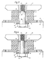
- the attachment component is in the form of a specially profiled bolt 23 which in the mounting additionally serves as an overload buffer.
- the bolt 23 has a first body portion 24 which lies within the internal cavity 25 of the tubular body 13 and extends downwards therefrom, as viewed in Figure 3, through the lower plate aperture 18 and a corresponding aperture 26 in the vehicle cross member 22.
- the diameter of the portion 24 lies substantially mid-way between the internal diameter of the upper plate 11 and the internal diameter of the tubular body 13.
- a second body portion 27 extends upwardly from the first portion 24, as viewed in Figure 3, and is screw-threaded for engagement with the engine support bracket 21.
- the second body portion is a close fit in the aperture of the upper member 11, and the shoulder region 28 at the step in diameter between the first and second portions 24,27 engages a shim 32 which bears against the portion of the face 14 surrounding the aperture; in consequence the shoulder region serves to clamp the upper member 11 to the engine support bracket 21.
- a head portion 29 extends from the lower end of the first body portion 24 of the bolt and a washer 30 secured to the head portion, for example by welding, supports an annular rubber buffer 31.
- the buffer 31 is positioned so as to be spaced slightly from a confronting surface of the vehicle cross member 22 when in an unloaded condition as shown in Figure 3. In the event of the resilient mounting being subject to a tensile loading the buffer 31 acts as an axial buffer which engages the cross member before damaging tensile loads are experienced by the tubular elastomeric body 13.
- the upper member 11 of Figure 3 may be spaced from member 21 by the base portion of an inverted cup having a downwardly and outwardly extending skirt portion depending from that base portion to act as an oil shield and protect the elastomeric material from possible contamination.
- a resilient mounting comprises a component part 10 as shown in Figure 1 arranged in combination with a buffer member 40 of modified form.
- the buffer member 40 corresponds with that shown in Figure 3 except that the metal portion 24 of buffer 21 is replaced by a metal portion 41 of smaller diameter, and is surrounded by a steel sleeve 42.
- the outer diameter of the sleeve 42 corresponds with the outer diameter of the portion 24.
Landscapes
- Engineering & Computer Science (AREA)
- General Engineering & Computer Science (AREA)
- Mechanical Engineering (AREA)
- Chemical & Material Sciences (AREA)
- Combustion & Propulsion (AREA)
- Transportation (AREA)
- Health & Medical Sciences (AREA)
- Child & Adolescent Psychology (AREA)
- Springs (AREA)
- Vibration Prevention Devices (AREA)
Applications Claiming Priority (4)
| Application Number | Priority Date | Filing Date | Title |
|---|---|---|---|
| GB8807658 | 1988-03-31 | ||
| GB888807658A GB8807658D0 (en) | 1988-03-31 | 1988-03-31 | Improvement in & relating to resilient mounting |
| GB8811198 | 1988-05-11 | ||
| GB888811198A GB8811198D0 (en) | 1988-05-11 | 1988-05-11 | Improvements in & relating to resilient mounting |
Publications (3)
| Publication Number | Publication Date |
|---|---|
| EP0336627A2 true EP0336627A2 (de) | 1989-10-11 |
| EP0336627A3 EP0336627A3 (en) | 1990-09-19 |
| EP0336627B1 EP0336627B1 (de) | 1994-08-03 |
Family
ID=26293714
Family Applications (1)
| Application Number | Title | Priority Date | Filing Date |
|---|---|---|---|
| EP89303035A Expired - Lifetime EP0336627B1 (de) | 1988-03-31 | 1989-03-28 | Elastisches Lager |
Country Status (5)
| Country | Link |
|---|---|
| US (1) | US4995598A (de) |
| EP (1) | EP0336627B1 (de) |
| CA (1) | CA1312587C (de) |
| DE (1) | DE68917183T2 (de) |
| GB (1) | GB2216984B (de) |
Cited By (3)
| Publication number | Priority date | Publication date | Assignee | Title |
|---|---|---|---|---|
| US7204744B2 (en) | 2002-10-18 | 2007-04-17 | Robert Bosch Gmbh | Hand-operated machine-tool comprising a vibration-damping rotary handle |
| US8522894B2 (en) | 2000-06-15 | 2013-09-03 | Robert Bosch Gmbh | Hand machine tool comprising at least one handle |
| EP2878851A1 (de) * | 2013-11-29 | 2015-06-03 | Jörn GmbH | Druckfeder mit Überlastungsschutz, insbesondere zwischen einem Blattfederende und einem Achskörper eines Lastkraftwagens |
Families Citing this family (38)
| Publication number | Priority date | Publication date | Assignee | Title |
|---|---|---|---|---|
| JP2687233B2 (ja) * | 1989-02-10 | 1997-12-08 | キヤノン株式会社 | シート送り装置 |
| JPH05324821A (ja) * | 1990-04-24 | 1993-12-10 | Sony Corp | 高解像度映像及び図形表示装置 |
| DE4119605C1 (de) * | 1991-06-14 | 1992-11-26 | Stop-Choc Schwingungstechnik Gmbh & Co Kg, 7253 Renningen, De | |
| DE4125249C2 (de) * | 1991-07-31 | 1994-03-03 | Freudenberg Carl Fa | Elastische Befestigungsvorrichtung zur Verbindung eines Ansaugrohres mit einer Verbrennungskraftmaschine |
| SE500084C2 (sv) * | 1992-07-06 | 1994-04-11 | Trelleborg Ind Ab | Eftergivligt, kraftöverförande fjäderelement |
| US5471770A (en) * | 1993-10-05 | 1995-12-05 | F&B Enterprises, Inc. | Rubberized wear pad assembly and method of making same |
| US5611157A (en) * | 1993-10-05 | 1997-03-18 | F & B Enterprises, Inc. | Wear pad assembly |
| GB9325147D0 (en) * | 1993-12-08 | 1994-02-09 | Dunlop Ltd | Elastomeric mounting |
| GB2308172B (en) * | 1995-12-15 | 1998-04-01 | Dunlop Ltd | Spring |
| US5800563A (en) * | 1995-12-22 | 1998-09-01 | Ohio Willow Wood Company | Impact reducing prosthetic pylon |
| US5676356A (en) * | 1996-05-30 | 1997-10-14 | The Boler Company | Flexible bolster |
| CA2281694C (en) * | 1996-12-17 | 2005-08-09 | Btr Industries Limited | Reinforced elastomeric spring |
| CN1090724C (zh) * | 1996-12-17 | 2002-09-11 | Btr工业有限公司 | 弹簧 |
| US5860382A (en) * | 1996-12-18 | 1999-01-19 | Hobdy; Miles A. | Turret bearing structure for vessels |
| US6026910A (en) * | 1998-01-13 | 2000-02-22 | Chicago Pneumatic Tool Company | Power tool and vibration isolator therefor |
| DE69908290T2 (de) * | 1998-06-15 | 2004-05-06 | Hitachi Construction Machinery Co., Ltd. | Baumaschine mit einem fahrerhaus |
| US6176548B1 (en) | 1998-10-23 | 2001-01-23 | Haworth, Inc. | Tilt mechanism for chair having adjustable spring characteristics |
| US6209958B1 (en) | 1998-10-23 | 2001-04-03 | Haworth, Inc. | Universal tilt mechanism for a chair |
| AU782017B2 (en) * | 1999-10-18 | 2005-06-30 | Lg Electronics Inc. | A driving unit for a drum type washing machine |
| US6416030B1 (en) * | 2000-06-29 | 2002-07-09 | Ford Global Technologies, Inc. | De-coupling mechanism for separating axial radial spring rates in an elastomeric mounting/isolation system |
| DE10106919B4 (de) * | 2001-02-15 | 2007-04-05 | Bayerische Motoren Werke Ag | Aggregatelager-Anordnung in einem Kraftfahrzeug |
| JP2003094969A (ja) * | 2001-09-27 | 2003-04-03 | Showa Corp | プロペラシャフトのブラケット取付構造 |
| US20030102613A1 (en) * | 2001-11-30 | 2003-06-05 | Alves Goldino Sousa | Elevator noise and vibration isolation system |
| US7997103B2 (en) | 2002-12-10 | 2011-08-16 | Lg Electronics Inc. | Tub having structurally strengthened rear wall and washing machine with the same therein |
| US20050040576A1 (en) * | 2003-08-20 | 2005-02-24 | Ernest Oxenknecht | Multi-axis isolator and assembly for the same |
| US7082896B2 (en) * | 2004-03-31 | 2006-08-01 | Kohler Co. | Mounting system allowing for thermal expansion of an engine of a generator set |
| KR100600337B1 (ko) * | 2005-05-26 | 2006-07-18 | 동일고무벨트주식회사 | 충격흡수기능을 가지는 언더캐리지 |
| US7810890B2 (en) * | 2006-10-13 | 2010-10-12 | Lynk, Inc. | Glide mechanism for roll out drawers and other items |
| GB2445571B (en) | 2007-01-10 | 2008-12-03 | Vistec Lithography Ltd | Apparatus support |
| US20090184229A1 (en) * | 2008-01-18 | 2009-07-23 | Caterpillar Inc. | Isolation mounting apparatus |
| CN103975509B (zh) | 2011-11-01 | 2017-06-20 | 康明斯发电Ip公司 | 发电机组底座 |
| US8966773B2 (en) | 2012-07-06 | 2015-03-03 | Techtronic Power Tools Technology Limited | Power tool including an anti-vibration handle |
| US8820701B1 (en) | 2012-11-28 | 2014-09-02 | Brunswick Corporation | Mounts, mounting arrangements, and methods of making mounting arrangements for supporting outboard motors with respect to marine vessels |
| CN103867620B (zh) * | 2014-03-03 | 2015-12-30 | 亚新科噪声与振动技术(安徽)有限公司 | 一种发动机左悬置软垫总成 |
| JP5979187B2 (ja) * | 2014-08-01 | 2016-08-24 | コベルコ建機株式会社 | 建設機械のキャブ支持構造 |
| KR102252508B1 (ko) | 2015-01-05 | 2021-05-14 | 엘지전자 주식회사 | 세탁기 |
| KR102070614B1 (ko) * | 2019-06-20 | 2020-01-29 | 주식회사 다원체어스 | 의자 좌판 지지용 조립형 탄성기구 |
| EP4465500A1 (de) * | 2023-05-16 | 2024-11-20 | GE Energy Power Conversion Technology Ltd | Montageanordnungen |
Family Cites Families (14)
| Publication number | Priority date | Publication date | Assignee | Title |
|---|---|---|---|---|
| DE706612C (de) * | 1934-07-15 | 1941-05-30 | Getefo Ges Fuer Tech Fortschri | Elastisches Lager |
| GB493119A (en) * | 1936-05-15 | 1938-10-03 | Maurice Francois Alexandre Jul | Improvements in and relating to resilient supports |
| FR829938A (fr) * | 1937-01-08 | 1938-07-11 | Perfectionnements aux amortisseurs en caoutchouc armé | |
| US2208532A (en) * | 1938-10-15 | 1940-07-16 | United Carr Fastener Corp | Nut member |
| US2869811A (en) * | 1951-05-31 | 1959-01-20 | Gomma Antivibranti Applic | Resilient mountings |
| FR1158530A (fr) * | 1956-09-05 | 1958-06-16 | Anciens Etablissements Panhard | Infrastructure pour véhicules automobiles |
| US3266139A (en) * | 1963-02-04 | 1966-08-16 | Bishop & Babcock Corp | Method of assembling vehicle body mount parts |
| GB1381142A (en) * | 1971-06-08 | 1975-01-22 | Gomma Antivibranti Applic | Springs |
| US3756551A (en) * | 1971-10-27 | 1973-09-04 | Lord Corp | Anti-vibration support |
| JPS53117704A (en) * | 1977-03-23 | 1978-10-14 | Boge Gmbh | Motor bearing device resilient like rubber |
| FR2543243A1 (fr) * | 1983-03-23 | 1984-09-28 | Caoutchouc Manuf Plastique | Suspension antivibratoire par elastomeres a compensation du fluage |
| JPS6018636A (ja) * | 1984-06-15 | 1985-01-30 | Hitachi Ltd | 圧縮機防振取付装置 |
| DE3529199A1 (de) * | 1984-08-16 | 1986-02-27 | Nissan Motor Co., Ltd., Yokohama, Kanagawa | Schwingungsdaempfungssystem |
| DE3734910A1 (de) * | 1987-10-15 | 1988-09-08 | Daimler Benz Ag | Schwingungsdaempfendes lager |
-
1989
- 1989-03-28 EP EP89303035A patent/EP0336627B1/de not_active Expired - Lifetime
- 1989-03-28 DE DE68917183T patent/DE68917183T2/de not_active Expired - Fee Related
- 1989-03-28 GB GB8906907A patent/GB2216984B/en not_active Expired - Lifetime
- 1989-03-29 CA CA000595107A patent/CA1312587C/en not_active Expired - Fee Related
- 1989-03-29 US US07/330,135 patent/US4995598A/en not_active Expired - Lifetime
Cited By (4)
| Publication number | Priority date | Publication date | Assignee | Title |
|---|---|---|---|---|
| US8522894B2 (en) | 2000-06-15 | 2013-09-03 | Robert Bosch Gmbh | Hand machine tool comprising at least one handle |
| US7204744B2 (en) | 2002-10-18 | 2007-04-17 | Robert Bosch Gmbh | Hand-operated machine-tool comprising a vibration-damping rotary handle |
| CN100464957C (zh) * | 2002-10-18 | 2009-03-04 | 罗伯特·博世有限公司 | 手持式工具机 |
| EP2878851A1 (de) * | 2013-11-29 | 2015-06-03 | Jörn GmbH | Druckfeder mit Überlastungsschutz, insbesondere zwischen einem Blattfederende und einem Achskörper eines Lastkraftwagens |
Also Published As
| Publication number | Publication date |
|---|---|
| GB2216984A (en) | 1989-10-18 |
| CA1312587C (en) | 1993-01-12 |
| GB2216984B (en) | 1992-02-12 |
| EP0336627A3 (en) | 1990-09-19 |
| EP0336627B1 (de) | 1994-08-03 |
| US4995598A (en) | 1991-02-26 |
| DE68917183D1 (de) | 1994-09-08 |
| GB8906907D0 (en) | 1989-05-10 |
| DE68917183T2 (de) | 1995-03-09 |
Similar Documents
| Publication | Publication Date | Title |
|---|---|---|
| US4995598A (en) | Resilient mounting | |
| EP0360793B1 (de) | Elastisches lasttragendes und schwingungsanpassungsfähiges lager | |
| US4286777A (en) | Mount to absorb shocks | |
| EP0069787B1 (de) | Polsterlagereinrichtung | |
| US2893722A (en) | Resilient mounting | |
| US5080335A (en) | Supporting bearing | |
| US5074535A (en) | Elastomeric mounting | |
| US6843352B2 (en) | Two stage shock absorber mount | |
| EP0262840B1 (de) | Elastomerlager | |
| US5842687A (en) | Self-aligning vibration mount with compound-angled flexing elements | |
| US4969634A (en) | Attachment of components to composite members | |
| US4895115A (en) | Mount with insulation for solid-conducted sound, in particular for an internal combustion engine | |
| US20060083585A1 (en) | Break-away cradle or sub-frame mount and retainer washer assembly | |
| JPH01145445A (ja) | 弾性マウンティング | |
| US6443439B1 (en) | Elastomeric mounting (B) | |
| EP0851143B1 (de) | Lager für ein Karosserie | |
| EP0042273B1 (de) | Schwingungsisolierende Lagerung | |
| US5890706A (en) | Hydraulic mounting | |
| EP0305728B1 (de) | Motorlager für Kraftfahrzeuge | |
| WO1999051482A1 (en) | Tube-shaped mount with restricted bulge area | |
| AU743908B2 (en) | Elastomeric mounting (D) | |
| US2880947A (en) | Motor mounting | |
| EP1094238A2 (de) | Elastische Lagereinrichtung und Lagerungsstruktur für elastische lagereinrichtungsbenutzende Vorrichtung | |
| KR19980056693U (ko) | 내진용 교좌장치 | |
| KR19980085331A (ko) | 차량의 마운팅 러버의 구조 |
Legal Events
| Date | Code | Title | Description |
|---|---|---|---|
| PUAI | Public reference made under article 153(3) epc to a published international application that has entered the european phase |
Free format text: ORIGINAL CODE: 0009012 |
|
| AK | Designated contracting states |
Kind code of ref document: A2 Designated state(s): BE DE FR NL SE |
|
| PUAL | Search report despatched |
Free format text: ORIGINAL CODE: 0009013 |
|
| AK | Designated contracting states |
Kind code of ref document: A3 Designated state(s): BE DE FR NL SE |
|
| 17P | Request for examination filed |
Effective date: 19900824 |
|
| 17Q | First examination report despatched |
Effective date: 19920320 |
|
| GRAA | (expected) grant |
Free format text: ORIGINAL CODE: 0009210 |
|
| AK | Designated contracting states |
Kind code of ref document: B1 Designated state(s): BE DE FR NL SE |
|
| PG25 | Lapsed in a contracting state [announced via postgrant information from national office to epo] |
Ref country code: NL Effective date: 19940803 Ref country code: BE Effective date: 19940803 |
|
| REF | Corresponds to: |
Ref document number: 68917183 Country of ref document: DE Date of ref document: 19940908 |
|
| ET | Fr: translation filed | ||
| NLV1 | Nl: lapsed or annulled due to failure to fulfill the requirements of art. 29p and 29m of the patents act | ||
| EAL | Se: european patent in force in sweden |
Ref document number: 89303035.3 |
|
| PLBE | No opposition filed within time limit |
Free format text: ORIGINAL CODE: 0009261 |
|
| STAA | Information on the status of an ep patent application or granted ep patent |
Free format text: STATUS: NO OPPOSITION FILED WITHIN TIME LIMIT |
|
| 26N | No opposition filed | ||
| REG | Reference to a national code |
Ref country code: FR Ref legal event code: TP |
|
| PGFP | Annual fee paid to national office [announced via postgrant information from national office to epo] |
Ref country code: SE Payment date: 20010306 Year of fee payment: 13 |
|
| PGFP | Annual fee paid to national office [announced via postgrant information from national office to epo] |
Ref country code: FR Payment date: 20010313 Year of fee payment: 13 |
|
| PGFP | Annual fee paid to national office [announced via postgrant information from national office to epo] |
Ref country code: DE Payment date: 20010319 Year of fee payment: 13 |
|
| PG25 | Lapsed in a contracting state [announced via postgrant information from national office to epo] |
Ref country code: SE Free format text: LAPSE BECAUSE OF NON-PAYMENT OF DUE FEES Effective date: 20020329 |
|
| PG25 | Lapsed in a contracting state [announced via postgrant information from national office to epo] |
Ref country code: DE Free format text: LAPSE BECAUSE OF NON-PAYMENT OF DUE FEES Effective date: 20021001 |
|
| EUG | Se: european patent has lapsed |
Ref document number: 89303035.3 |
|
| PG25 | Lapsed in a contracting state [announced via postgrant information from national office to epo] |
Ref country code: FR Free format text: LAPSE BECAUSE OF NON-PAYMENT OF DUE FEES Effective date: 20021129 |
|
| REG | Reference to a national code |
Ref country code: FR Ref legal event code: ST |