EP0336754A2 - Organe de commande de l'élément chauffant d'un rouleau de fixage par fusion - Google Patents
Organe de commande de l'élément chauffant d'un rouleau de fixage par fusion Download PDFInfo
- Publication number
- EP0336754A2 EP0336754A2 EP89303402A EP89303402A EP0336754A2 EP 0336754 A2 EP0336754 A2 EP 0336754A2 EP 89303402 A EP89303402 A EP 89303402A EP 89303402 A EP89303402 A EP 89303402A EP 0336754 A2 EP0336754 A2 EP 0336754A2
- Authority
- EP
- European Patent Office
- Prior art keywords
- heat source
- fuser
- source
- roll structure
- roll
- Prior art date
- Legal status (The legal status is an assumption and is not a legal conclusion. Google has not performed a legal analysis and makes no representation as to the accuracy of the status listed.)
- Granted
Links
Images
Classifications
-
- G—PHYSICS
- G03—PHOTOGRAPHY; CINEMATOGRAPHY; ANALOGOUS TECHNIQUES USING WAVES OTHER THAN OPTICAL WAVES; ELECTROGRAPHY; HOLOGRAPHY
- G03G—ELECTROGRAPHY; ELECTROPHOTOGRAPHY; MAGNETOGRAPHY
- G03G15/00—Apparatus for electrographic processes using a charge pattern
- G03G15/20—Apparatus for electrographic processes using a charge pattern for fixing, e.g. by using heat
- G03G15/2003—Apparatus for electrographic processes using a charge pattern for fixing, e.g. by using heat using heat
- G03G15/2014—Apparatus for electrographic processes using a charge pattern for fixing, e.g. by using heat using heat using contact heat
- G03G15/2039—Apparatus for electrographic processes using a charge pattern for fixing, e.g. by using heat using heat using contact heat with means for controlling the fixing temperature
Definitions
- This invention relates generally to xerographic copying apparatus, and more particularly, it relates to the heat and pressure fixing of particulate thermoplastic toner by direct contact with a heated fuser roller.
- a light image of an original to be copied is typically recorded in the form of a latent electrostatic image upon a photosensitive member with subsequent rendering of the latent image visible by the application of electroscopic marking particles, commonly referred to as toner.
- the visual toner image can be either fixed directly upon the photosensitive member or transferred from the member to another support, such as a sheet of plain paper, with subsequent affixing of the image thereto in one of various ways, for example, as by heat and pressure.
- One approach to heat and pressure fusing of electroscopic toner images onto a support has been to pass the support with the toner images thereon between a pair of opposed roller members, at least one of which is internally heated.
- the support member to which the toner images are electrostatically adhered is moved through the nip formed between the rolls with the toner image contacting the heated (fuser) roll thereby to effect heating of the toner images within the nip.
- toner particles will be offset to the fuser roll by an insufficient application of heat to the surface thereof (i.e. "cold" offsetting); by imperfections in the properties of the surface of the roll; or by the toner particles insufficiently adhering to the copy sheet by the electrostatic forces which normally hold them there.
- toner particles may be transferred to the surface of the fuser roll with subsequent transfer to the backup roll during periods of time when no copy paper is in the nip.
- toner particles can be picked up by the fuser and/or backup roll during fusing of duplex copies or simply from the surroundings of the reproducing apparatus.
- a thin layer of silicone oil is applied to the surface of the heated roll to form an interface between the roll surface and the toner images carried on the support material.
- a low surface energy layer is presented to the toner as it passes through the fuser nip and thereby prevents toner from offsetting to the fuser roll surface.
- a fuser roll construction of the type described above is fabricated by applying in any suitable manner a solid layer of abhesive material to a rigid core or substrate such as the solid Teflon outer surface or covering of the aforementioned arrangement.
- External fuser roll heating for example, using a heat lamp, has been recognized to have substantial unit manufacturing cost (UMC) and size benefits over the more conventional internal roll heating methods for high speed applications (about 600 mm per second).
- UMC unit manufacturing cost
- external fuser roll heating exhibits significantly increased fire risk as well.
- the viability of external heating of a fuser roll is dependent on the provision of a fail-safe method of insuring that a fire will not occur.
- fuser roll temperature controllers use either a triac or two silicon controlled rectifiers (SCRs) to switch the external heater on and off.
- SCRs silicon controlled rectifiers
- zero crossing occurs 120 per second.
- shutdown occurs within 1/120th of a second of loss of the control signal.
- the problem with these switching devices is that they often fail by short circuiting. In this case, the over-temperature sensor near the fuser roll would eventually shut down the fuser.
- such sensors take tens of seconds to minutes to activate in the event of a triac or SCR failure, far too long for external heating.
- over-temperature sensors provide no protection should the fuser roll stop rotating.
- the present invention provides, in a contact fuser apparatus having a fuser roll structure rotating in contact with a backup roll structure an forming a nip therewith through which copy substrates carrying toner images pass with the toner images contacting the fuser roll structure: a heat source for elevating the temperature of said fuser roll structure; switching means operably coupling said heat source and a source of power; and means for periodically actuating said switch means whereby said heat source is operated at approximately full power dissipation at a duty cycle low enough to prevent overloading of said heat source.
- the arrangement should be such that any circuit failure causing continuous energization of said heat source will lead to power interruption and safe shutdown through failure of the heat source before fire or overheating can occur.
- the present invention further provides fuser apparatus having a heated fuser structure rotatable in contact with a backup roll structure to form a nip therewith through which copy substrates carrying toner images can pass with the toner images contacting the fuser roll structure; a heat source operable to heat the fuser roll structure; switching means operably coupling said heat source with a power source, the arrangement being such that continuous energization of the heat source by the power source will cause failure of the heat source through overloading; and means for periodically actuating said switching means whereby the heat source is operated at a duty cycle low enough to prevent overloading.
- a slotted disk is attached to a fuser roll for use as an optical chopper that, in conjunction with a light sensor, delivers a string of electrical pulses only when the fuser roll is rotating.
- the pulses are conditioned by the selection of a slot width and/or use of a capacitance filter to insure that the pulses are shorter than the half cycle of the AC supply to the heat source (in the case of a 60 Hz supply that is less than 1/120th of a second).
- the pulse frequency is much lower than that of the AC supply so the duty cycle of the heat source is low (e.g. less than 20% and the lamp is energized less than one fifth of the cycles).
- Zero crossing sensing circuitry could, of course be employed to reduce RF noise generated when a triac or SCR is activated mid cycle by delaying the turn-on command until the start of the next cycle.
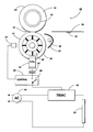
- FIG. 1 is a side elevational schematic view of a heat and pressure fuser.
- a roll fuser apparatus is generally indicated 10.
- the fuser apparatus shown comprises an externally heated roll structure 12 cooperating with a non-heated backup or pressure roll structure 14 to form a nip 16 through which a copy substrate 18 passes with toner images 20 formed thereon in a well known manner.
- this invention is not restricted to apparatus having an externally heated roller structure and pertains also to apparatus having an internally heated roll structure.
- the toner images 20 contact the heated roll structure while a force is applied between the roll structures in a conventional manner to create pressure therebetween resulting in the deformation of one of the roll structures by the other to thereby form the nip 16.
- the substrate passes out of the nip 16, it is stripped from the heated roll structure by a stripping device (not shown) after which it is free to move along a predetermined path toward the exit of the machine (not shown) in which the fuser apparatus 10 is to be utilized.
- a temperature sensor 24 is provided for sensing the surface temperature of the externally heated roll structure 12 and in conjunction with conventional control 26 maintains the surface temperature at a predetermined value, for example, in the order of 375-400 °F.
- the heated roll structure 12 comprises a cylinder 28 having an external heat lamp 30 and reflector 31 adjacent the outer surface of said heated roll structure.
- the heating element radiates heat to an outer surface of the structure 2 which preferably comprises silicone or VlTON (trademark of E. du Pont de Nemours & Co.) rubber having a thickness in the range 0.010 in. (0.25 mm) to about 0.100 in. (2.5 mm).
- the backup roll structure 14 comprises a solid metal core 32 to which can be adhered a relatively thick layer 34 of deformable material for example an elastomer known as ethylene-propylene terpolymer which is based on stereosperific linear polymers of ethylene, propylene and small amounts of non-conjugated diene which is commonly referred to as EPDM which layer carries a thin overcoat of PFA.
- PFA is a fluorinated copolymer of perfluoroalkoxy and tetrafluoroethylene Due to the construction of the backup roll structure shown it is deformed by the harder heated roll structure 12 when the required pressure is applied therebetween, the pressure being a function of the desired deformation which corresponds to the desired length of the nip 16.
- the invention can also be used in a fuser wherein the heated (fuser) roll is deformed by the pressure, or backup, roll.
- a slotted disk 36 is attached to the fuser roll and serves as an optical chopper that, in conjunction with a light sensor or photocell 38, delivers a string of electrical pulses only when the fuser roll is rotating.
- the pulses are conditioned by a capacitance filter 40 to insure that the pulses are shorter than the half cycle of the AC supply to the heat lamp 30 (in the case of a 60 Hz supply, that is less than 1/120th of a second).
- Proper selection of the slot widths of the chopper can also be used to condition the pulses.
- the pulse frequency is much lower than that of the AC supply so the lamp duty cycle is low (e.g. less than 20% and the lamp is energized less than one fifth of the cycles).
- the conditioned pulses are fed to switching means (comprising a triac 42) via the electronic switch 44 which is part of the temperature control circuitry and which is activated when the roll temperature falls below the predetermined temperature set point.
- the triac operatively connects the AC power source 46 with the external heat lamp 30.
- Zero crossing sensing circuitry could, of course be employed to reduce RF noise generated by when the triac is activated mid cycle by delaying the turn-on command until the start of the next cycle.
- the triac 42 could be replaced by other suitable switching means, for example one or more silicon controlled rectifier.
- the low duty cycle of the lamp 30 affords fail-safe protection in the event of a triac or SCR short circuit.
- a fuser lamp filament is essentially a time averaging device for the time frames below a few tenths of seconds.
- a 10 volt lamp could be run either continuously at 10 volts or at 100 volts at a 10% duty cycle so long as the cycle times are short in comparison to the lamp filament's thermal time constant.
- This time constant is the time required for the lamp filament to cool to 1/e of its operating temperature referenced to the ambient temperature once the power is interrupted.
- this is the time for the temperature to reach: Ta + (To - Ta)/e where Ta is the ambient temperature, To is the filament operating temperature, and e is the natural logarithm.
- the lamp is specified for full power dissipation at a 10% duty cycle at 120 VAC so that it would be significantly overloaded should the triac short circuit and cause the duty cycle to effectively increase to 100%. The system would thus fail safely through relatively inexpensive lamp burn-out rather than by a potentially catastrophic fire.
Landscapes
- Physics & Mathematics (AREA)
- General Physics & Mathematics (AREA)
- Fixing For Electrophotography (AREA)
Applications Claiming Priority (2)
| Application Number | Priority Date | Filing Date | Title |
|---|---|---|---|
| US07/179,369 US4897692A (en) | 1988-04-08 | 1988-04-08 | Fail safe fuser lamp control |
| US179369 | 1988-04-08 |
Publications (3)
| Publication Number | Publication Date |
|---|---|
| EP0336754A2 true EP0336754A2 (fr) | 1989-10-11 |
| EP0336754A3 EP0336754A3 (en) | 1990-08-01 |
| EP0336754B1 EP0336754B1 (fr) | 1994-06-01 |
Family
ID=22656307
Family Applications (1)
| Application Number | Title | Priority Date | Filing Date |
|---|---|---|---|
| EP89303402A Expired - Lifetime EP0336754B1 (fr) | 1988-04-08 | 1989-04-06 | Organe de commande de l'élément chauffant d'un rouleau de fixage par fusion |
Country Status (4)
| Country | Link |
|---|---|
| US (1) | US4897692A (fr) |
| EP (1) | EP0336754B1 (fr) |
| JP (1) | JPH01306883A (fr) |
| DE (1) | DE68915604T2 (fr) |
Cited By (2)
| Publication number | Priority date | Publication date | Assignee | Title |
|---|---|---|---|---|
| EP0527420A3 (en) * | 1991-08-09 | 1994-05-18 | Minolta Camera Kk | Fixing device |
| EP0840179A1 (fr) * | 1996-10-29 | 1998-05-06 | Sharp Kabushiki Kaisha | Appareil de fixage |
Families Citing this family (3)
| Publication number | Priority date | Publication date | Assignee | Title |
|---|---|---|---|---|
| DE19547387B4 (de) * | 1995-12-19 | 2005-11-10 | Bayerische Motoren Werke Ag | Verfahren zur Übertragung von Informationen für Fahrzeuge mittels eines Funksignalsystems |
| US6188854B1 (en) * | 1999-11-09 | 2001-02-13 | Tommy C. Coleman | Non-contact thermal temperature controller |
| JP5773724B2 (ja) * | 2011-04-20 | 2015-09-02 | キヤノン株式会社 | 像加熱装置 |
Family Cites Families (19)
| Publication number | Priority date | Publication date | Assignee | Title |
|---|---|---|---|---|
| US2859381A (en) * | 1956-03-20 | 1958-11-04 | Sylvania Electric Prod | Fuse for incandescent lamp |
| US3211950A (en) * | 1963-02-20 | 1965-10-12 | Gen Electric | Electric incandescent lamp with integral fuse |
| US3346768A (en) * | 1964-10-29 | 1967-10-10 | Gen Electric | Incandescent lamp with a fuse integral with the lead-in structure |
| US3272967A (en) * | 1965-05-04 | 1966-09-13 | Viewlex Inc | Lamp control means |
| US3742191A (en) * | 1969-07-15 | 1973-06-26 | Irtronics Inc | Infrared temperature sensor and control for use with heated, moving bodies |
| US3833794A (en) * | 1972-11-02 | 1974-09-03 | Xerox Corp | Fixing unit for use in a duplicating apparatus |
| US3916256A (en) * | 1973-06-21 | 1975-10-28 | Fuji Xerox Co Ltd | Protective circuit in a temperature regulator for the thermal fixing device of a duplicator |
| US3849628A (en) * | 1973-07-25 | 1974-11-19 | Xerox Corp | Non-contact temperature sensor for a roll fuser of a xerographic reproduction apparatus |
| US4097782A (en) * | 1975-12-15 | 1978-06-27 | Hiram Darden Chambliss | Energy saving means reducing power used by lamps |
| JPS5418747A (en) * | 1977-07-13 | 1979-02-13 | Ricoh Co Ltd | Temperature controller of copying machine |
| JPS5767971A (en) * | 1980-10-14 | 1982-04-24 | Sharp Corp | Preventing device for abnormal rise of temperature of heat generator |
| JPS5779974A (en) * | 1980-11-07 | 1982-05-19 | Fuji Xerox Co Ltd | Heat fixing device |
| US4541708A (en) * | 1982-01-09 | 1985-09-17 | Canon Kabushiki Kaisha | Heating-fixing device |
| JPS58144868A (ja) * | 1982-02-24 | 1983-08-29 | Hitachi Ltd | 定着装置 |
| US4556779A (en) * | 1982-03-18 | 1985-12-03 | Minolta Camera Kabushiki Kaisha | Temperature control arrangement for heat roller |
| JPS58173772A (ja) * | 1982-04-07 | 1983-10-12 | Hitachi Ltd | 熱定着装置 |
| US4506144A (en) * | 1982-07-19 | 1985-03-19 | Cincinnati Milacron Inc. | Control for radiant heating |
| US4496829A (en) * | 1982-12-10 | 1985-01-29 | International Business Machines Corporation | Bang-bang dual-mode integral controller with proportional control output useful for temperature control |
| JPS60154277A (ja) * | 1984-01-24 | 1985-08-13 | Ricoh Co Ltd | 定着温度制御方法 |
-
1988
- 1988-04-08 US US07/179,369 patent/US4897692A/en not_active Expired - Fee Related
-
1989
- 1989-04-03 JP JP1084626A patent/JPH01306883A/ja active Pending
- 1989-04-06 EP EP89303402A patent/EP0336754B1/fr not_active Expired - Lifetime
- 1989-04-06 DE DE68915604T patent/DE68915604T2/de not_active Expired - Fee Related
Cited By (3)
| Publication number | Priority date | Publication date | Assignee | Title |
|---|---|---|---|---|
| EP0527420A3 (en) * | 1991-08-09 | 1994-05-18 | Minolta Camera Kk | Fixing device |
| EP0840179A1 (fr) * | 1996-10-29 | 1998-05-06 | Sharp Kabushiki Kaisha | Appareil de fixage |
| US6088549A (en) * | 1996-10-29 | 2000-07-11 | Sharp Kabushiki Kaisha | Fixing device having an externally-heated fixing roller |
Also Published As
| Publication number | Publication date |
|---|---|
| DE68915604D1 (de) | 1994-07-07 |
| EP0336754A3 (en) | 1990-08-01 |
| US4897692A (en) | 1990-01-30 |
| EP0336754B1 (fr) | 1994-06-01 |
| DE68915604T2 (de) | 1994-12-22 |
| JPH01306883A (ja) | 1989-12-11 |
Similar Documents
| Publication | Publication Date | Title |
|---|---|---|
| US7283145B2 (en) | Image heating apparatus and heater therefor | |
| JP3170857B2 (ja) | 加熱装置 | |
| JPH0215074B2 (fr) | ||
| JPH06202512A (ja) | 加熱装置及び画像記録装置 | |
| CA1132182A (fr) | Appareil a rouleau de fusion et systeme connexe | |
| JP2708867B2 (ja) | 加熱定着装置 | |
| US5729812A (en) | Heat and pressure fuser utilizing rigid rolls and belts to form an extended contact zone between the belts including preheat and pressure zones | |
| EP0370520A2 (fr) | Appareil de fixation d'image | |
| US4770116A (en) | Contact fuser apparatus with release agent management system | |
| KR100491577B1 (ko) | 화상형성 장치의 정착기의 온도제어 방법 | |
| JPH0519659A (ja) | 画像形成装置 | |
| US4897692A (en) | Fail safe fuser lamp control | |
| JP4593903B2 (ja) | 加熱装置 | |
| WO2007013659A1 (fr) | Dispositif d’imagerie thermique | |
| US5438392A (en) | Image fixing apparatus with energy cut-off | |
| JPH10312133A (ja) | 加熱装置及び画像形成装置 | |
| US5392105A (en) | Release agent management system for applying release agent material which is solid at room temperature | |
| JP2000260553A (ja) | 加熱装置、加熱定着装置および画像形成装置 | |
| JP2746921B2 (ja) | 画像形成装置の熱定着装置 | |
| GB2108430A (en) | Thermal switch for fuser | |
| JPH08106234A (ja) | 加熱装置 | |
| JPH0748125B2 (ja) | 画像形成装置 | |
| JP3102448B2 (ja) | 定着装置の温度制御装置 | |
| JPH1165353A (ja) | 定着装置 | |
| JPH096160A (ja) | 加熱装置及び画像形成装置 |
Legal Events
| Date | Code | Title | Description |
|---|---|---|---|
| PUAI | Public reference made under article 153(3) epc to a published international application that has entered the european phase |
Free format text: ORIGINAL CODE: 0009012 |
|
| AK | Designated contracting states |
Kind code of ref document: A2 Designated state(s): DE FR GB |
|
| PUAL | Search report despatched |
Free format text: ORIGINAL CODE: 0009013 |
|
| AK | Designated contracting states |
Kind code of ref document: A3 Designated state(s): DE FR GB |
|
| 17P | Request for examination filed |
Effective date: 19910123 |
|
| 17Q | First examination report despatched |
Effective date: 19920710 |
|
| GRAA | (expected) grant |
Free format text: ORIGINAL CODE: 0009210 |
|
| AK | Designated contracting states |
Kind code of ref document: B1 Designated state(s): DE FR GB |
|
| REF | Corresponds to: |
Ref document number: 68915604 Country of ref document: DE Date of ref document: 19940707 |
|
| ET | Fr: translation filed | ||
| PLBE | No opposition filed within time limit |
Free format text: ORIGINAL CODE: 0009261 |
|
| STAA | Information on the status of an ep patent application or granted ep patent |
Free format text: STATUS: NO OPPOSITION FILED WITHIN TIME LIMIT |
|
| 26N | No opposition filed | ||
| PGFP | Annual fee paid to national office [announced via postgrant information from national office to epo] |
Ref country code: GB Payment date: 19970401 Year of fee payment: 9 |
|
| PGFP | Annual fee paid to national office [announced via postgrant information from national office to epo] |
Ref country code: FR Payment date: 19970409 Year of fee payment: 9 |
|
| PGFP | Annual fee paid to national office [announced via postgrant information from national office to epo] |
Ref country code: DE Payment date: 19970414 Year of fee payment: 9 |
|
| PG25 | Lapsed in a contracting state [announced via postgrant information from national office to epo] |
Ref country code: GB Free format text: LAPSE BECAUSE OF NON-PAYMENT OF DUE FEES Effective date: 19980406 |
|
| PG25 | Lapsed in a contracting state [announced via postgrant information from national office to epo] |
Ref country code: FR Free format text: THE PATENT HAS BEEN ANNULLED BY A DECISION OF A NATIONAL AUTHORITY Effective date: 19980430 |
|
| GBPC | Gb: european patent ceased through non-payment of renewal fee |
Effective date: 19980406 |
|
| PG25 | Lapsed in a contracting state [announced via postgrant information from national office to epo] |
Ref country code: DE Free format text: LAPSE BECAUSE OF NON-PAYMENT OF DUE FEES Effective date: 19990202 |
|
| REG | Reference to a national code |
Ref country code: FR Ref legal event code: ST |