EP0336860A1 - Elektroakustische Kapsel mit angekoppelter Spule - Google Patents
Elektroakustische Kapsel mit angekoppelter Spule Download PDFInfo
- Publication number
- EP0336860A1 EP0336860A1 EP89420116A EP89420116A EP0336860A1 EP 0336860 A1 EP0336860 A1 EP 0336860A1 EP 89420116 A EP89420116 A EP 89420116A EP 89420116 A EP89420116 A EP 89420116A EP 0336860 A1 EP0336860 A1 EP 0336860A1
- Authority
- EP
- European Patent Office
- Prior art keywords
- capsule
- coil body
- coil
- transducer according
- connectors
- Prior art date
- Legal status (The legal status is an assumption and is not a legal conclusion. Google has not performed a legal analysis and makes no representation as to the accuracy of the status listed.)
- Ceased
Links
Images
Classifications
-
- H—ELECTRICITY
- H04—ELECTRIC COMMUNICATION TECHNIQUE
- H04M—TELEPHONIC COMMUNICATION
- H04M1/00—Substation equipment, e.g. for use by subscribers
- H04M1/02—Constructional features of telephone sets
- H04M1/21—Combinations with auxiliary equipment, e.g. with clocks or memoranda pads
- H04M1/215—Combinations with auxiliary equipment, e.g. with clocks or memoranda pads by non-intrusive coupling means, e.g. acoustic couplers
Definitions
- the present invention relates to telephone receiver capsules, generally comprising a box containing a vibrating element for transforming into sound vibrations the electrical signals conveyed on its input terminals by a supply line.
- the vibrating element is made up of a membrane held around its periphery in a capsule case.
- the housing comprises a base body provided with a central cavity, the periphery of which forms a bearing surface for the periphery of the vibrating membrane; the housing further comprises a cover connecting at its periphery to the base body, and comprising an interior recess communicating with the exterior through at least one orifice; the periphery of the cover has an internal annular relief bearing on the periphery of the membrane to keep it pressed against the periphery of the cavity of the base body.
- the central cavity of the base body defines, with the vibrating membrane, an interior base cavity.
- the interior cover recess defines, with the vibrating membrane, an interior cover cavity.
- hearing aids for the hearing impaired are designed to amplify the acoustic vibrations received and make them perceptible by the ear.
- some prostheses include an adjustment device which, in the "T" position, makes them suitable for picking up a magnetic field. These prostheses thus make it possible to function correctly when the transducer is of the electromagnetic type.
- telephone receiving capsules comprising auxiliary coils, supplied by the electrical signal for controlling the vibrating membrane, and producing an auxiliary magnetic field capable of being picked up by hearing aids.
- Document DE-U-8 715 846 describes a piezoelectric capsule to which a coil body can relate, forming a separate assembly from the capsule.
- the coil body has an annular shape which fits on a cylindrical part of the capsule housing.
- the coil body includes housings in which coil connectors are disposed, forming the ends of the coil winding.
- the capsule connectors When the coil body is engaged on the capsule housing, the capsule connectors gradually penetrate inside the housings of the coil body. At the end of engagement, the capsule connectors are entirely disposed inside the housings of the coil body, and come close to the coil connectors.
- Reported elastic lugs provide assembly and connection between the capsule connectors and the coil connectors.
- the addition of the coil and its connection require the provision of attached elastic lugs, which constitute additional parts.
- the adaptation is relatively difficult, and complicates the assembly.
- the mode of coupling of the coil on the capsule body imposes a particular geometrical shape on the receiving capsule.
- a family of capsules of different diameters requires providing a corresponding family of coils of different diameters.
- the type of connection provided by an additional part, introduces contact impedances into the main electrical circuit of the capsule, and risks disturbing its operation due to the adaptation of a coil.
- a stock of traditional capsules can easily be transformed into a stock of auxiliary coil capsules for the hearing impaired.
- Another object of the invention is to provide particular electrical connections making it possible to ensure correct operation of the capsule even in the case where the coil becomes defective, for example in the case where the coil wire is cut.
- the adaptation of the module comprising the auxiliary magnetic coil does not introduce any parasitic contact impedance in series in the main supply circuit of the capsule itself.
- the particular mode of coupling according to the invention does not impose any particular geometric shape on the receiving capsule.
- the coil body according to the invention forms a separate assembly from the capsule body.
- the capsule housing comprises a rear face provided with means for adapting the coil body, and the coil body comprises a front face provided with fastening means on the rear face of the capsule housing.
- the coil body has two axial passages through which axial capsule connectors penetrate. Elastic conductors, disposed in the axial passages of the coil body and electrically connected to the coil winding, remain in elastic support on the capsule connectors when the coil body is fitted on the rear face of the capsule housing.
- the axial capsule connectors have a length greater than the thickness of the coil body, so that their ends protrude from the rear face of the coil body and remain accessible for the electrical connection of the assembly when the coil body is adapted. on the back of the capsule case.
- the coil body forms a cavity open towards the front, and communicating towards the inside of the capsule by a filter.
- the coil body is closed towards the rear, and is provided with sealing means, thus forming a third acoustic cavity.
- the coil body is open towards the rear.
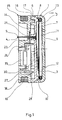
- the capsule 1 comprises a vibrating element in the form of a membrane 2.
- a piezoelectric membrane of known type composed of a thin metallic or insulating film, forming the base substrate of the membrane, and on which is secured at least one piezoelectric ceramic layer whose faces are metallized and constitute electrodes.
- Electrical connection means 3 for example of a known type such as elastic metal tabs, ensure the connection of the electrodes to output connectors 4 and 5.
- the output connectors 4 and 5 are metal tabs, substantially rectangular planar , arranged in two parallel axial directions substantially perpendicular to the general plane of the membrane 2.
- the membrane 2, for example of substantially circular shape is held around its periphery in a capsule case.
- the housing further comprises a cover 9, which is connected at its periphery 10 to the base body 6.
- the cover 9 comprises an internal recess 11 communicating with the outside through a series of orifices such as the orifice 12, regularly distributed in the wall of the cover as shown in the figures.
- the cover recess 11 defines an acoustic cover cavity; the central cavity 7 of the base body defines an acoustic cavity of the base body; the acoustic cavities are separated from each other by the membrane 2.
- An annular peripheral elastic seal 13, inserted between the membrane 2 and the cover 9, is pressed against the periphery of the membrane.
- the base body 6 comprises in known manner passages for the introduction and the maintenance of the connectors 4 and 5 which are fixed to it.
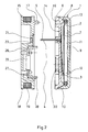
- the rear face 14 of the capsule 1 comprises means for adapting a coil body 15.
- the rear face 14 is generally planar, and the adaptation means are holes of circular section such as the hole 16, distributed around the periphery of the rear face 14 of the capsule, the holes being intended to receive spikes such as the spike 17 on the front face of the coil body 15.
- the coil body 15 comprises a structure forming a coil frame 18, on which is wound the electric wire forming the coil winding 19.
- the coil body comprises two axial passages 20 and 21, arranged so that, when the coil body 15 is fitted against the rear face of the base body 6 of the capsule 1, the connectors 4 and 5 of the capsule pass through the passages 20 and 21.
- the coil body 15 has a thickness slightly less than the length of the connectors 4 and 5, so that the ends of the connectors 4 and 5 protrude slightly from the rear face of the coil body 15 when the coil body is adapted on the capsule, as shown in FIG. 1.
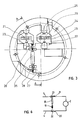
- Each of the axial passages 20 and 21 is provided with means of electrical connection of the coil constituted by plates of metal connection 22 and 23 respectively, held in position in the coil body 15 by hooking means, and comprising passages for connectors 4 and 5.
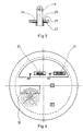
- the connection plates 22 and 23 include cutouts forming tongues, by example the tabs 24 and 25 of the plate 22. As shown in section in Figure 5, the tabs 24 and 25 are supported on the two edges of the corresponding connector 4 of the capsule.
- the connector 4 pushes the tabs 24 and 25 and spreads them slightly; it follows that the tabs are braced on the edges of the connector 4, and that they provide good quality electrical contact, while prohibiting or considerably slowing the possible withdrawal of the connector from the passage 20.
- the plates 22 and 23 provide both the electrical connection and non-return means preventing disassembly.
- the coil body further carries an electrical resistance 35, a first terminal 26 of which is welded to the connection plate 23, and the second terminal 27 of which receives the end 28 of the electric wire coil winding 19.
- the other end 29 of the coil winding wire is electrically connected to the second connection plate 22, as shown in FIG. 3.
- the front face of the coil body 15 is generally flat, to conform to the rear face 14 of the capsule body, and comprises pins such as the pin 17, preferably of square section.
- the section of the studs 17 is adapted to forcefully engage in holes with corresponding round sections such as the hole 16 of the capsule 1.
- pins 17 of different section for example circular, which are housed in holes 16 of different section, for example square of the capsule.
- the coil body 15 forms a cavity open towards the front, and communicating with the interior of the capsule via a filter 30.
- the cavity of the coil body is also open towards the rear, by openings such as opening 31.
- the operation of the device is as follows: starting from a disassembled position shown in FIG. 2, in which the capsule 1 and the coil body 15 are two distinct and separate elements, the coil body 15 is brought closer to the capsule 1, the front face of the coil body 15 being disposed towards the rear face 14 of the capsule.
- Connectors 4 and 5 are engaged in the corresponding passages 20 and 21; the connectors 4 and 5 push the corresponding tabs such as the tabs 24 and 25, and the pins 17 progressively engage in the corresponding holes 16.
- the pins 17 are fully engaged in the holes 16.
- the electrical connection is then automatically ensured, by the fact that the connectors 4 and 5 are in contact of the connection plates 20 and 21.
- the electrical connection of the assembly is made by the accessible ends of the connectors 4 and 5.
- FIG. 6 illustrates the electrical connection diagram of the various organs of the transducer according to the invention in the assembly position shown in FIG. 1.
- the assembly formed by the coil 19 and the resistor 35 in series is connected in parallel on the membrane 2; the main membrane electrical circuit 2, formed by the membrane and the connectors 4 and 5 is not modified by the addition of the assembly formed by the coil 19 and the resistor 35, the plates 22 and 23 simply rubbing against connectors 4 and 5 while leaving their free ends for connection of the assembly to an external electrical circuit.
Landscapes
- Engineering & Computer Science (AREA)
- Signal Processing (AREA)
- Details Of Connecting Devices For Male And Female Coupling (AREA)
- Coils Or Transformers For Communication (AREA)
- Piezo-Electric Transducers For Audible Bands (AREA)
Applications Claiming Priority (2)
| Application Number | Priority Date | Filing Date | Title |
|---|---|---|---|
| FR8804733 | 1988-04-01 | ||
| FR8804733A FR2629662B1 (fr) | 1988-04-01 | 1988-04-01 | Capsule electroacoustique a bobine rapportee |
Publications (1)
| Publication Number | Publication Date |
|---|---|
| EP0336860A1 true EP0336860A1 (de) | 1989-10-11 |
Family
ID=9365157
Family Applications (1)
| Application Number | Title | Priority Date | Filing Date |
|---|---|---|---|
| EP89420116A Ceased EP0336860A1 (de) | 1988-04-01 | 1989-03-30 | Elektroakustische Kapsel mit angekoppelter Spule |
Country Status (4)
| Country | Link |
|---|---|
| US (1) | US4944017A (de) |
| EP (1) | EP0336860A1 (de) |
| JP (1) | JPH01293000A (de) |
| FR (1) | FR2629662B1 (de) |
Cited By (3)
| Publication number | Priority date | Publication date | Assignee | Title |
|---|---|---|---|---|
| EP0456968A3 (en) * | 1990-05-14 | 1992-12-09 | Alcatel Dial Face S.P.A. | Piezoelectric transducer |
| EP0613323A1 (de) * | 1993-02-26 | 1994-08-31 | Alcatel Dial Face S.P.A. | Piezokeramische Kapsel für Fernsprechinstrumente |
| CN102088651A (zh) * | 2011-01-07 | 2011-06-08 | 瑞声声学科技(深圳)有限公司 | 电声换能器 |
Families Citing this family (8)
| Publication number | Priority date | Publication date | Assignee | Title |
|---|---|---|---|---|
| JPH0733519Y2 (ja) * | 1990-02-08 | 1995-07-31 | フォスター電機株式会社 | 受話器 |
| CN1038179C (zh) * | 1992-09-30 | 1998-04-22 | 星精密株式会社 | 电音响变换器 |
| NL1004669C2 (nl) * | 1996-12-02 | 1998-06-03 | Microtronic Nederland Bv | Transducer. |
| JP3373151B2 (ja) * | 1998-04-24 | 2003-02-04 | 株式会社シチズン電子 | 電磁型発音体 |
| DE69935057T2 (de) * | 1998-05-15 | 2007-11-22 | Koninklijke Philips Electronics N.V. | Gerät zum gebrauch am ohr oder entfernt vom ohr |
| US6658134B1 (en) | 1999-08-16 | 2003-12-02 | Sonionmicrotronic Nederland B.V. | Shock improvement for an electroacoustic transducer |
| JP4337078B2 (ja) * | 2001-04-23 | 2009-09-30 | 日本電気株式会社 | スピーカ装置 |
| US20030003864A1 (en) * | 2001-06-28 | 2003-01-02 | Antony Locke | Cover for a mobile telephone handset |
Citations (2)
| Publication number | Priority date | Publication date | Assignee | Title |
|---|---|---|---|---|
| DE3140746A1 (de) * | 1981-10-14 | 1983-04-21 | Fernsprech- und Signalbaugesellschaft mbH Schüler & Vershoven, 4300 Essen | Hoer- und/oder sprechkapsel |
| DE8715846U1 (de) * | 1987-11-30 | 1988-01-14 | Siemens AG, 1000 Berlin und 8000 München | Piezoelektrischer Wandler mit Hörhilfe |
-
1988
- 1988-04-01 FR FR8804733A patent/FR2629662B1/fr not_active Expired - Fee Related
-
1989
- 1989-03-23 US US07/327,736 patent/US4944017A/en not_active Expired - Fee Related
- 1989-03-30 EP EP89420116A patent/EP0336860A1/de not_active Ceased
- 1989-03-31 JP JP1081320A patent/JPH01293000A/ja active Pending
Patent Citations (2)
| Publication number | Priority date | Publication date | Assignee | Title |
|---|---|---|---|---|
| DE3140746A1 (de) * | 1981-10-14 | 1983-04-21 | Fernsprech- und Signalbaugesellschaft mbH Schüler & Vershoven, 4300 Essen | Hoer- und/oder sprechkapsel |
| DE8715846U1 (de) * | 1987-11-30 | 1988-01-14 | Siemens AG, 1000 Berlin und 8000 München | Piezoelektrischer Wandler mit Hörhilfe |
Cited By (5)
| Publication number | Priority date | Publication date | Assignee | Title |
|---|---|---|---|---|
| EP0456968A3 (en) * | 1990-05-14 | 1992-12-09 | Alcatel Dial Face S.P.A. | Piezoelectric transducer |
| EP0613323A1 (de) * | 1993-02-26 | 1994-08-31 | Alcatel Dial Face S.P.A. | Piezokeramische Kapsel für Fernsprechinstrumente |
| US5479521A (en) * | 1993-02-26 | 1995-12-26 | Alcatel Dial Face S.P.A. | Piezoceramic capsule for telephone instruments |
| RU2134030C1 (ru) * | 1993-02-26 | 1999-07-27 | Алкател Дайл Фейс С.п.А. | Пьезокерамическая капсула для телефонных аппаратов |
| CN102088651A (zh) * | 2011-01-07 | 2011-06-08 | 瑞声声学科技(深圳)有限公司 | 电声换能器 |
Also Published As
| Publication number | Publication date |
|---|---|
| US4944017A (en) | 1990-07-24 |
| FR2629662B1 (fr) | 1991-05-10 |
| JPH01293000A (ja) | 1989-11-27 |
| FR2629662A1 (fr) | 1989-10-06 |
Similar Documents
| Publication | Publication Date | Title |
|---|---|---|
| CA2172919C (fr) | Agencement de connexion pour fils conducteurs electriques et module, notamment de type bloc de jonction, equipe d'un tel agencement | |
| EP0403371B1 (de) | Elektrischer Stecker zum Verbinden eines geschirmten Mehrfachleiterkabels an eine in einem Gestell befindliche elektrische Einheit | |
| EP1143573A1 (de) | Koaxialer Verbinder | |
| EP0336860A1 (de) | Elektroakustische Kapsel mit angekoppelter Spule | |
| EP1416582A1 (de) | Tragbare elektronische Vorrichtung mit einer elektrischen Verbindung in dem Vorrichtungsgehäuse | |
| FR2818084A1 (fr) | Micro haut-parleur | |
| FR2951862A1 (fr) | Dispositif de commutation electromagnetique pour demarreur | |
| FR2805669A1 (fr) | Connecteur pour circuit imprime et equipement le comportant | |
| FR2629660A1 (fr) | Capsule piezoelectrique a pinces de connection electrique laterales | |
| FR2589636A1 (fr) | Bloc connecteur amovible a utiliser dans un assemblage de connecteurs | |
| EP0228741B1 (de) | Testvorrichtung für ein Gehäuse ohne Kontaktnadeln, versehen mit einem mit Hochfrequenz arbeitenden Chip mit integrierter Schaltung | |
| EP0611224B1 (de) | Differentialschutzeinheit mit auf Funktion testbarer Untereinheit | |
| EP1454516B1 (de) | Energiemodul und energiemodulbaugruppe | |
| FR2914788A1 (fr) | Ensemble porte-contacts electriques | |
| EP1173905A1 (de) | Eingangs/ausgangssteckverbinderanordnung mit erdungsanordnung für abgeschirmte kabel und verfahren zur herstellung und zum zusammenbau eines solchen steckverbinders | |
| FR2500706A1 (fr) | Transducteur electrostatique-acoustique | |
| EP0169792A1 (de) | Telefonhörerkapsel kompatibel mit Hörhilfen für Schwerhörige | |
| EP0459876A1 (de) | Terminal-Adapter als Verbindungsgerät | |
| EP0861012A1 (de) | Lautsprecher und Telefongerät mit einem solchen Lautsprecher | |
| FR2587162A1 (fr) | Dispositif de fermeture de chambre acoustique pour un transducteur electroacoustique monte dans un boitier | |
| FR2554963A1 (fr) | Condensateur de decouplage et procede de fabrication de celui-ci | |
| FR2824426A1 (fr) | Element de connecteur electrique coaxial | |
| EP3312948B1 (de) | Elektrische steckdose, die ein monoblockteil zur halterung und aufnahme von höckereinsätzen umfasst, und verfahren zum zusammenbau einer solchen elektrischen steckdose | |
| FR2696586A1 (fr) | Connecteur à diode/filtre. | |
| EP4117002A1 (de) | Hilfsmodul für eine elektrische schaltvorrichtung, entsprechende schaltvorrichtung und entsprechendes überwachungssystem |
Legal Events
| Date | Code | Title | Description |
|---|---|---|---|
| PUAI | Public reference made under article 153(3) epc to a published international application that has entered the european phase |
Free format text: ORIGINAL CODE: 0009012 |
|
| AK | Designated contracting states |
Kind code of ref document: A1 Designated state(s): AT BE CH DE ES FR GB GR IT LI LU NL SE |
|
| 17P | Request for examination filed |
Effective date: 19900213 |
|
| 17Q | First examination report despatched |
Effective date: 19920504 |
|
| STAA | Information on the status of an ep patent application or granted ep patent |
Free format text: STATUS: THE APPLICATION HAS BEEN REFUSED |
|
| 18R | Application refused |
Effective date: 19921026 |