EP0337099A2 - Dispositif de commande d'un moteur à combustion interne dans des véhicules - Google Patents
Dispositif de commande d'un moteur à combustion interne dans des véhicules Download PDFInfo
- Publication number
- EP0337099A2 EP0337099A2 EP19890103735 EP89103735A EP0337099A2 EP 0337099 A2 EP0337099 A2 EP 0337099A2 EP 19890103735 EP19890103735 EP 19890103735 EP 89103735 A EP89103735 A EP 89103735A EP 0337099 A2 EP0337099 A2 EP 0337099A2
- Authority
- EP
- European Patent Office
- Prior art keywords
- throttle valve
- coupling part
- valve shaft
- coupling
- armature
- Prior art date
- Legal status (The legal status is an assumption and is not a legal conclusion. Google has not performed a legal analysis and makes no representation as to the accuracy of the status listed.)
- Withdrawn
Links
Images

Classifications
-
- F—MECHANICAL ENGINEERING; LIGHTING; HEATING; WEAPONS; BLASTING
- F02—COMBUSTION ENGINES; HOT-GAS OR COMBUSTION-PRODUCT ENGINE PLANTS
- F02D—CONTROLLING COMBUSTION ENGINES
- F02D11/00—Arrangements for, or adaptations to, non-automatic engine control initiation means, e.g. operator initiated
- F02D11/06—Arrangements for, or adaptations to, non-automatic engine control initiation means, e.g. operator initiated characterised by non-mechanical control linkages, e.g. fluid control linkages or by control linkages with power drive or assistance
- F02D11/10—Arrangements for, or adaptations to, non-automatic engine control initiation means, e.g. operator initiated characterised by non-mechanical control linkages, e.g. fluid control linkages or by control linkages with power drive or assistance of the electric type
- F02D11/107—Safety-related aspects
-
- F—MECHANICAL ENGINEERING; LIGHTING; HEATING; WEAPONS; BLASTING
- F02—COMBUSTION ENGINES; HOT-GAS OR COMBUSTION-PRODUCT ENGINE PLANTS
- F02D—CONTROLLING COMBUSTION ENGINES
- F02D11/00—Arrangements for, or adaptations to, non-automatic engine control initiation means, e.g. operator initiated
- F02D11/06—Arrangements for, or adaptations to, non-automatic engine control initiation means, e.g. operator initiated characterised by non-mechanical control linkages, e.g. fluid control linkages or by control linkages with power drive or assistance
- F02D11/10—Arrangements for, or adaptations to, non-automatic engine control initiation means, e.g. operator initiated characterised by non-mechanical control linkages, e.g. fluid control linkages or by control linkages with power drive or assistance of the electric type
- F02D2011/101—Arrangements for, or adaptations to, non-automatic engine control initiation means, e.g. operator initiated characterised by non-mechanical control linkages, e.g. fluid control linkages or by control linkages with power drive or assistance of the electric type characterised by the means for actuating the throttles
- F02D2011/103—Arrangements for, or adaptations to, non-automatic engine control initiation means, e.g. operator initiated characterised by non-mechanical control linkages, e.g. fluid control linkages or by control linkages with power drive or assistance of the electric type characterised by the means for actuating the throttles at least one throttle being alternatively mechanically linked to the pedal or moved by an electric actuator
Definitions
- the invention relates to a device for controlling an internal combustion engine in vehicles of the type defined in the preamble of claim 1.
- control electronics are designed in such a way that the control is switched off when serious errors occur and the internal combustion engine comes to a standstill due to the return spring being forced to close the throttle valve. In such cases, the additional emergency equipment ensures that the vehicle is maneuverable.
- the drive lever or the accelerator pedal is via a Bowden cable coupled with the setpoint device and adjusts the latter according to the driving lever position.
- the rotational position of the setpoint generator is transmitted as an electrical signal to control electronics, which, taking into account further control variables such as the slip of the drive wheels, generates an actuating signal for the servomotor that swivels the throttle valve.
- the emergency drive device consists of a variable-length mechanical transmission element which is designed as a rod and can be connected to the setpoint device via a connecting lever.
- the link lever can also be towed towards full load by a rocker arm.
- the rocker arm connects the drive lever to the setpoint device.
- the length variability of the rod is realized by two compression springs with different preloads. In the event of a malfunction, when the electrical power control fails, when the actuator is de-energized, when the drive lever is actuated, the connecting lever is dragged along by the rocker arm and thus the transmission rod is compressed until the throttle valve is adjusted due to the spring force of the stronger compression spring. Driving with half the load of the internal combustion engine is then possible.
- the device according to the invention with the characterizing features of claim 1 has the advantage that during the trouble-free operation of the drive lever is completely uncoupled from the throttle valve, so that there is no additional friction for the torque-sensitive actuator acting on the throttle valve shaft. Only in the event of a malfunction, i.e. when the servomotor is switched off, is the driving lever automatically and driver-independently coupled to the throttle valve, and the latter is mechanically adjusted when the driving lever is actuated in emergency driving mode.
- the automatic locking of the throttle valve and drive lever can be achieved particularly advantageously by de-energizing the clutch magnet in the event of a malfunction in the absence of power to the servomotor and the revolving connection between the two clutch parts released by energizing the clutch magnet by means of a clutch spring is automatically restored. If the electromagnet is connected in series with the servomotor, no separate power output stage is required to excite the electromagnet through the control electronics.
- the clutch according to the invention between the throttle valve and the drive lever and the respective fixed connection of the one clutch part with the throttle valve and the other clutch part with the drive lever opens up the possibility of accommodating the setpoint device in the throttle valve, servomotor and control electronics unit, the so-called throttle valve actuator, if appropriate a preferred embodiment of the invention, the setpoint device is arranged on the coupling part connected to the drive lever.
- An electrical actual value sensor which detects the rotational position of the throttle valve is expediently arranged on the first coupling part connected to the throttle valve shaft or on the throttle valve shaft itself.
- the setpoint generator and actual value generator can advantageously be combined on a single element.
- the slideways of the two potentiometers are arranged on a fixed insulating plate, while the sliders contacting the slideways are each rotatably coupled to a coupling part.
- the insulating plate is arranged coaxially with the throttle valve shaft.
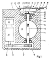
- the throttle valve actuator shown schematically in FIG. 1 is used to control the power of an internal combustion engine of a vehicle which, according to the position of the drive lever or accelerator pedal (not shown), pivots a throttle valve 10 in the intake duct 11 of the internal combustion engine in such a way that it releases a certain opening cross section and thus the Quantity of the mixture supplied to the internal combustion engine and ultimately the power of the internal combustion engine are determined.
- the throttle valve 10 is seated in a rotationally fixed manner on a throttle valve shaft 12, which is held in bearings 13, 14 in a housing 15 of the throttle valve actuator.
- a gearwheel 16 On the throttle valve shaft 12 there is a gearwheel 16 which is driven by a toothed wheel 18 via a toothed belt 17 and which is seated on the output shaft 19 of an electronically commutated drive motor which is reversible in the direction of rotation, hereinafter referred to as servomotor 20.
- the servomotor 20 is controlled by control electronics 21 which take into account the electrical output signal of a setpoint generator 22 to be described converts further manipulated variables, such as slip of the drive wheels, into an actuating voltage for the servomotor 20.
- the electrical output signal of the setpoint generator 22 is a direct measure of the position of the accelerator pedal or drive lever. If the internal combustion engine is to be accelerated by depressing the drive lever, the setpoint generator 22 is adjusted via the drive lever.
- the control electronics 21 generates an actuating voltage for the servomotor 20 from the electrical output signal of the setpoint generator 22, and the latter rotates the throttle valve shaft 12 by a certain angle of rotation.
- the control electronics 21 is designed so that when a serious error occurs, the servomotor 20 is switched off and returns to its closed position (FIG. 1) with the throttle valve 10 by a return spring (not shown). If the mixture is not supplied, the internal combustion engine comes to a standstill.
- an emergency driving device 23 is provided, which in such a case mechanically connects the driving lever directly to the throttle valve shaft 12 and thus transmits the pivoting of the driving lever directly to the throttle valve 10.
- the emergency drive device 23 has an electromagnetic clutch 24, the first clutch part 241 of which is fixedly connected to the throttle valve shaft 12 and the second clutch part 242 of which is permanently connected to the drive lever.
- the clutch 24 is designed in such a way that the two clutch parts 241, 242 are disengaged when the electrical control is in undisturbed operation and come into engagement with one another automatically in the event of a fault and the associated switching off of the servomotor 20.
- the first coupling part 241 is formed by an end flange 25 seated at the end of the throttle valve shaft 12.
- the second Coupling part 242 which is arranged at a distance from the end flange 25 and concentrically surrounds the throttle valve shaft 12, is pivotally mounted in the housing 15 of the throttle valve actuator, but is secured against axial displacement in the housing 15 (cf. FIG. 1).
- the second coupling part 242 contains the electromagnet 26 with a cup-shaped yoke 27, a cylindrical excitation winding 28 and the armature 29 covering the pot opening.
- the armature 29 is designed as a rope pulley 30 which is fixed in a rotationally fixed manner on a sleeve 31 with a T-shaped cross section.
- the sleeve 31 is freely rotating and axially displaceable on the throttle valve shaft 12.
- a coupling spring 32 designed as a compression spring, which is supported on the one hand on the rope pulley 30 and on the other hand on the yoke 27 and the sleeve 31 via the rope pulley 30 seeks to move against the magnetic force of the electromagnet 26.
- the electromagnet 26 is switched off, the sleeve 31 with the pulley 30 on the throttle valve shaft 12 is shifted so far that the opposing end faces 311 of the sleeve 31 and 251 of the end flange 25 abut one another.
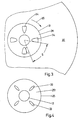
- Axially projecting claws 33 and 34 are arranged both on the end face 251 and on the end face 311 and are arranged distributed uniformly over the circumference of the end faces 251 and 311.
- four claws 33 and 34 are provided on each end face 251 and 311, respectively, which are offset from one another by 90 ° in the circumferential direction.
- the dimensions of the claws 33, 34 in the circumferential direction are dimensioned to be relatively small, so that when the claws 33, 34 are in engagement with one another, the end flange 25 and sleeve 31 can rotate through a rotation path s without the other part being entrained in rotation (FIG. 3).
- This play, designated s, in the clutch 24 is used to reduce the power of the internal combustion engine in emergency operation.
- a Bowden cable 36 acts on the sheave 30 with a tangential direction of attack.
- the strand 37 of the Bowden cable 36 is fastened to the cable pulley 30, while the sleeve 38 of the Bowden cable 36 is supported on the end face at a stop bracket 39 on the housing 15.
- the Bowden cable 36 connects the cable pulley 30 directly to the driving lever, so that each pivoting of the driving lever is converted into a corresponding rotation of the cable pulley 30.
- the connecting lines of the excitation winding 28 shown schematically in FIG. 2 are connected in parallel to the connections of the servomotor 20.
- the setpoint generator 22 shown schematically in FIG. 1 is designed as a rotary angle potentiometer, in which a grinder 40 contacts an annular slideway 41 and, depending on the rotational position of the grinder 40, a corresponding output voltage can be taken from the slideway 41 and / or from the grinder 40.
- the sliding path 41 is arranged as an outer circular path on an insulating plate 42 which concentrically surrounds the throttle valve shaft 12 and is fastened in the housing 15.
- the grinder 40 here designed as a double grinder, is fastened to the yoke 27 and adjusts itself according to its rotational movement on the sliding track 41.
- an electrical actual value transmitter 43 which detects the rotational position of the throttle valve 10 and whose electrical output signal is a measure of is the pivot position of the throttle valve 10 and is also supplied to the control electronics 21.
- the actual value transmitter 43 like the setpoint transmitter 22, is designed as a rotation angle potentiometer, the sliding track 44 of which is arranged concentrically to the sliding track 41 on the insulating plate 42.
- the grinder 45 of the actual value transmitter 43 is rotatably connected to the throttle valve shaft 12.
- the control electronics 21 deliver a specific actuating signal to the servomotor 20, which opens the throttle valve 10 to such an extent that the internal combustion engine is idling.
- the servomotor 20 When the servomotor 20 is energized, the excitation winding 28 of the electromagnetic clutch 24 is also energized. Due to the magnetic force, the sheave 30 is axially displaced against the force of the clutch spring 32 until it rests on the end ring surface of the yoke 27. The claws 33, 34 disengage due to the displacement of the rope pulley 30.
- the clutch 24 is disengaged, the pulley 30 and the throttle valve shaft 12 can rotate unaffected by one another.
- the driver will depress the driving lever.
- the pivoting movement of the driving lever is converted via the Bowden cable 36 into a pivoting movement of the rope pulley 30, and since it rests against the yoke 27, into a pivoting movement of the entire coupling part 242.
- the grinder 40 of the setpoint generator 22 is rotated on the sliding track 41, as a result of which the electrical output signal of the setpoint generator 22 increases.
- the enlarged output signal of the setpoint generator 22 fed to the control electronics 21 triggers the supply of a corresponding actuating signal to the servomotor 20 which swivels the throttle valve shaft 12 via the toothed belt drive 16 - 18, so that the passage opening in the intake duct 11 which is released by the throttle valve 10 increases.
- the control motor 21 stops the servomotor 20 and the throttle valve 10 rotates back into its closed position (FIG. 1) through the return spring.
- the passage opening in the intake duct 11 is thus completely closed and the internal combustion engine comes to a standstill due to the lack of a fuel mixture.
- the servomotor 20 is switched off, the energization of the excitation winding 28 of the electromagnet 26 also ceases, and the clutch spring 32 pushes the rope pulley 30 with the sleeve 31 axially outward until the claws 33, 34 of the end flange 25 and sleeve 31 axially on the respective end faces 311 or 251 and engage with each other.
- the cable pulley 30 is still pivoted in the arrow direction 35 in FIG. 3 via the Bowden cable 36.
- the cams 34 on the end face 11 of the sleeve 31 come into contact with the cams 33 on the end face 251 of the end flange 25 and take them along in the direction of rotation.
- the throttle valve shaft 12 is thus rotated and the throttle valve 10 is moved into a swivel position in which it in turn opens a specific opening in the intake duct 11.
- the internal combustion engine receives fuel mixture again and can drive the vehicle in a kind of emergency operation. Through the play s between the claws 33 and 34, the power of the internal combustion engine is reduced when the drive lever is fully depressed.
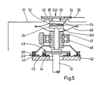
- the electromagnetic coupling 24 and the setpoint generator 22 are somewhat modified in their structural design, although a somewhat larger axial overall length must be accepted.
- the second coupling part 242 no longer encloses the throttle valve shaft 12, but is an extension of the Throttle valve shaft 12 rotatably held in housing 15 in a bearing schematically indicated by 50.
- the sheave 30 is shown, which is connected in a rotationally fixed manner to an end flange 46, which lies opposite the end flange 25 and, in the same way as the sleeve 31 in FIG Front flange 25 can be brought into engagement.
- the electromagnet 26 is not shown here.
- Setpoint generator 22 and actual value transmitter 43 are in turn designed as an angle of rotation potentiometer and arranged in the same way as in FIG. 1.
- the two sliding tracks 41 and 44 are arranged in a concentric arrangement on the insulating plate 42 coaxial with the throttle valve shaft 12 and the grinder 45 of the actual value transmitter 43 is again in Execution as a double grinder attached to the throttle valve shaft 12.
- the grinder 40 of the setpoint generator 22 is fastened as a double grinder to a sleeve 47 which is arranged coaxially with the throttle valve shaft 12, surrounds it and is rotatably held in a bearing 48 in the housing 15.
- the sleeve 47 is connected in a rotationally fixed manner to the end flange 46 of the second coupling part 242 via a driver 49.
- the modified throttle valve actuator is identical to that described above. Since the angle of rotation of the angle of rotation potentiometer is less than 180 °, the slideways of setpoint generator 22 and actual value generator 43 can also be arranged as ring segments on the same circular path that runs coaxially to throttle valve shaft 12. The grinders remain attached to the throttle valve shaft 12 or to the sleeve 47, but are designed as single grinders.
- the former is either connected in series with the servomotor 20 or connected directly to its terminals in parallel connection. so that an electrical safety shutdown downstream of the servomotor 20 in the control electronics 21 also ends the energization of the excitation winding 28 in the event of a fault.
Landscapes
- Engineering & Computer Science (AREA)
- Chemical & Material Sciences (AREA)
- Combustion & Propulsion (AREA)
- Mechanical Engineering (AREA)
- General Engineering & Computer Science (AREA)
- Control Of Throttle Valves Provided In The Intake System Or In The Exhaust System (AREA)
Applications Claiming Priority (2)
| Application Number | Priority Date | Filing Date | Title |
|---|---|---|---|
| DE3811892 | 1988-04-09 | ||
| DE3811892A DE3811892A1 (de) | 1988-04-09 | 1988-04-09 | Vorrichtung zur regelung einer brennkraftmaschine in fahrzeugen |
Publications (2)
| Publication Number | Publication Date |
|---|---|
| EP0337099A2 true EP0337099A2 (fr) | 1989-10-18 |
| EP0337099A3 EP0337099A3 (fr) | 1989-12-27 |
Family
ID=6351671
Family Applications (1)
| Application Number | Title | Priority Date | Filing Date |
|---|---|---|---|
| EP89103735A Withdrawn EP0337099A3 (fr) | 1988-04-09 | 1989-03-03 | Dispositif de commande d'un moteur à combustion interne dans des véhicules |
Country Status (4)
| Country | Link |
|---|---|
| US (1) | US5002032A (fr) |
| EP (1) | EP0337099A3 (fr) |
| JP (1) | JPH01301934A (fr) |
| DE (1) | DE3811892A1 (fr) |
Cited By (9)
| Publication number | Priority date | Publication date | Assignee | Title |
|---|---|---|---|---|
| EP0402521A1 (fr) * | 1989-06-10 | 1990-12-19 | VDO Adolf Schindling AG | Dispositif de réglage de charge |
| WO1991018194A1 (fr) * | 1990-05-18 | 1991-11-28 | Audi Ag | Regulateur de papillon a commande electrique |
| EP0444239A3 (en) * | 1990-02-26 | 1992-07-08 | Vdo Adolf Schindling Ag | Throttle valve assembly |
| EP0638716A1 (fr) * | 1993-08-13 | 1995-02-15 | Pierburg Gmbh | Dispositif de papillon pour moteurs à combustion interne |
| WO2000008320A1 (fr) * | 1998-08-01 | 2000-02-17 | Filterwerk Mann+Hummel Gmbh | Systeme de canaux, en particulier collecteur d'admission d'un moteur a combustion interne |
| EP0982483A2 (fr) | 1998-08-25 | 2000-03-01 | Mannesmann VDO Aktiengesellschaft | Dispositif d'entraínement |
| EP1126146A2 (fr) | 2000-02-18 | 2001-08-22 | Mannesmann VDO Aktiengesellschaft | Corps de papillon |
| EP1357453A3 (fr) * | 2002-04-24 | 2007-06-20 | BorgWarner Inc. | Actionneur électrique |
| WO2008034656A1 (fr) * | 2006-09-22 | 2008-03-27 | SIEMENS AKTIENGESELLSCHAFT öSTERREICH | Dispositif d'acquisition de l'angle de rotation d'un papillon entraîné par moteur électrique |
Families Citing this family (26)
| Publication number | Priority date | Publication date | Assignee | Title |
|---|---|---|---|---|
| DE4022825A1 (de) * | 1989-08-22 | 1991-02-28 | Bosch Gmbh Robert | Einrichtung mit einem eine leistung einer antriebsmaschine bestimmenden drosselorgan |
| DE3936875A1 (de) * | 1989-11-06 | 1991-05-08 | Hella Kg Hueck & Co | Drosselklappe fuer eine brennkraftmaschine |
| DE3940178A1 (de) * | 1989-12-05 | 1991-06-06 | Teves Gmbh Alfred | Stelleinrichtung fuer ein regelorgan |
| DE4005905A1 (de) * | 1990-02-24 | 1991-08-29 | Bayerische Motoren Werke Ag | Elektromotorisch betaetigbare leistungssteuervorrichtung einer brennkraftmaschine |
| DE4021691C2 (de) * | 1990-07-07 | 2001-06-28 | Mannesmann Vdo Ag | Potentiometer |
| DE4028702A1 (de) * | 1990-09-10 | 1992-03-12 | Bosch Gmbh Robert | Stelleinrichtung |
| JPH04224241A (ja) * | 1990-12-26 | 1992-08-13 | Aisin Seiki Co Ltd | スロットル制御装置 |
| JPH04231631A (ja) * | 1990-12-27 | 1992-08-20 | Aisin Seiki Co Ltd | スロットル制御装置 |
| JP3205002B2 (ja) * | 1991-05-20 | 2001-09-04 | 株式会社日立製作所 | スロットルアクチュエータ |
| DE4129960C2 (de) * | 1991-09-10 | 2000-11-16 | Hella Kg Hueck & Co | Einrichtung zum Einstellen der Fahrgeschwindigkeit eines Kraftfahrzeuges |
| JP2921234B2 (ja) * | 1992-02-05 | 1999-07-19 | 日産自動車株式会社 | 電子式スロットル駆動装置 |
| JPH0650201A (ja) * | 1992-04-30 | 1994-02-22 | Nippondenso Co Ltd | スロットル弁の駆動装置 |
| JP2758535B2 (ja) * | 1992-07-16 | 1998-05-28 | 株式会社日立製作所 | 電子スロットル制御装置 |
| JPH07139376A (ja) * | 1993-11-19 | 1995-05-30 | Aisin Seiki Co Ltd | スロットル制御装置 |
| JPH10315798A (ja) * | 1997-03-17 | 1998-12-02 | Aisin Seiki Co Ltd | スロットル開度制御用アクチュエータ |
| DE19721239A1 (de) * | 1997-05-21 | 1998-12-03 | Hella Kg Hueck & Co | Vorrichtung zur Betätigung der Drosselklappe eines Verbrennungsmotors |
| JP4509406B2 (ja) * | 2000-03-17 | 2010-07-21 | ヤマハ発動機株式会社 | 水ジェット推進艇のエンジン出力制御装置 |
| NL1014911C2 (nl) | 2000-04-11 | 2001-10-12 | Skf Eng & Res Centre Bv | Elektrisch schroefactuatorsysteem. |
| NL1014912C2 (nl) * | 2000-04-11 | 2001-10-12 | Skf Eng & Res Centre Bv | Handregelmiddelen. |
| DE10319882A1 (de) * | 2003-05-03 | 2004-11-18 | Daimlerchrysler Ag | Leistungssteller mit Fail-Safe-Vorrichtung |
| US7086379B2 (en) * | 2004-07-07 | 2006-08-08 | Buell Motorcycle Company | Power control device and method for a motorcycle |
| DE102005042347B4 (de) * | 2005-09-07 | 2024-06-06 | Zf Friedrichshafen Ag | Automatisches oder automatisiertes Kraftfahrzeug-Getriebe und Verfahren zur Steuerung dessen, mit einem Notfahrbetrieb und einem Normalfahrbetrieb |
| DE102006008051B3 (de) * | 2006-02-21 | 2007-11-29 | Siemens Ag | Adaptives Positionierverfahren eines Stellglieds |
| US20090007884A1 (en) * | 2007-07-02 | 2009-01-08 | Bunne Jonathan M | Dual throttle assembly with electronic override |
| CN206555476U (zh) * | 2016-03-06 | 2017-10-13 | 张大伟 | 阀门控制装置 |
| EP3800716B1 (fr) * | 2019-10-03 | 2022-05-04 | Marelli Europe S.p.A. | Papillon des gaz pour régler l'introduction d'un gaz dans une pile à combustible et véhicule à entraînement électrique comprenant le papillon des gaz |
Family Cites Families (11)
| Publication number | Priority date | Publication date | Assignee | Title |
|---|---|---|---|---|
| DE2646793A1 (de) * | 1976-10-16 | 1978-04-20 | Bosch Gmbh Robert | Elektrisch ansteuerbare stellvorrichtung |
| GB2068456B (en) * | 1980-01-30 | 1983-09-28 | Lucas Industries Ltd | Internal combustion engine throttle valve control linkage |
| JPS59122742A (ja) * | 1982-12-28 | 1984-07-16 | Mazda Motor Corp | エンジンのスロツトル弁制御装置 |
| JPS59153945A (ja) * | 1983-02-21 | 1984-09-01 | Nissan Motor Co Ltd | スロツトルバルブ制御装置 |
| DE3307968A1 (de) * | 1983-03-07 | 1984-09-13 | Vdo Adolf Schindling Ag, 6000 Frankfurt | Einrichtung zur uebertragung der stellposition eines sollwertgebers |
| FR2585409B1 (fr) * | 1985-07-26 | 1989-08-18 | Marchal Equip Auto | Dispositif d'actionnement electrique d'un organe, notamment d'un volet de papillon de carburateur |
| DE3609849C1 (de) * | 1986-03-22 | 1987-07-30 | Daimler Benz Ag | Einrichtung zur Regulierung einer Brennkraftmaschine in einem Kraftfahrzeug |
| JPS643239A (en) * | 1987-06-25 | 1989-01-09 | Mitsubishi Motors Corp | Drive by-wire type throttle valve control device with fail-safe mechanism |
| JPH0737770B2 (ja) * | 1987-07-24 | 1995-04-26 | 日産自動車株式会社 | 車両用スロットル開度制御装置 |
| DE3730239A1 (de) * | 1987-09-09 | 1989-03-30 | Pierburg Gmbh | Elektrisch ansteuerbare stellvorrichtung zum verstellen der drosselklappe einer brenngemischdrosseleinrichtung von brennkraftmaschinen |
| JPS6487836A (en) * | 1987-09-30 | 1989-03-31 | Mitsubishi Motors Corp | Safety device for throttle actuator |
-
1988
- 1988-04-09 DE DE3811892A patent/DE3811892A1/de not_active Ceased
-
1989
- 1989-03-03 EP EP89103735A patent/EP0337099A3/fr not_active Withdrawn
- 1989-04-07 US US07/334,427 patent/US5002032A/en not_active Expired - Fee Related
- 1989-04-10 JP JP1088204A patent/JPH01301934A/ja active Pending
Cited By (12)
| Publication number | Priority date | Publication date | Assignee | Title |
|---|---|---|---|---|
| EP0402521A1 (fr) * | 1989-06-10 | 1990-12-19 | VDO Adolf Schindling AG | Dispositif de réglage de charge |
| US5027766A (en) * | 1989-06-10 | 1991-07-02 | Vdo Adolf Schindling Ag | Load adjustment device |
| EP0444239A3 (en) * | 1990-02-26 | 1992-07-08 | Vdo Adolf Schindling Ag | Throttle valve assembly |
| WO1991018194A1 (fr) * | 1990-05-18 | 1991-11-28 | Audi Ag | Regulateur de papillon a commande electrique |
| EP0638716A1 (fr) * | 1993-08-13 | 1995-02-15 | Pierburg Gmbh | Dispositif de papillon pour moteurs à combustion interne |
| WO2000008320A1 (fr) * | 1998-08-01 | 2000-02-17 | Filterwerk Mann+Hummel Gmbh | Systeme de canaux, en particulier collecteur d'admission d'un moteur a combustion interne |
| EP0982483A2 (fr) | 1998-08-25 | 2000-03-01 | Mannesmann VDO Aktiengesellschaft | Dispositif d'entraínement |
| EP1126146A2 (fr) | 2000-02-18 | 2001-08-22 | Mannesmann VDO Aktiengesellschaft | Corps de papillon |
| US6646395B2 (en) | 2000-02-18 | 2003-11-11 | Mannesmann Vdo Ag | Throttle body |
| EP1357453A3 (fr) * | 2002-04-24 | 2007-06-20 | BorgWarner Inc. | Actionneur électrique |
| WO2008034656A1 (fr) * | 2006-09-22 | 2008-03-27 | SIEMENS AKTIENGESELLSCHAFT öSTERREICH | Dispositif d'acquisition de l'angle de rotation d'un papillon entraîné par moteur électrique |
| US7798121B2 (en) | 2006-09-22 | 2010-09-21 | Melecs Ews Gmbh & Co Kg | Apparatus for detecting the angle of rotation for a throttle valve operated by means of an electric motor |
Also Published As
| Publication number | Publication date |
|---|---|
| DE3811892A1 (de) | 1989-10-19 |
| EP0337099A3 (fr) | 1989-12-27 |
| US5002032A (en) | 1991-03-26 |
| JPH01301934A (ja) | 1989-12-06 |
Similar Documents
| Publication | Publication Date | Title |
|---|---|---|
| EP0337099A2 (fr) | Dispositif de commande d'un moteur à combustion interne dans des véhicules | |
| EP0326553B2 (fr) | Systeme pour le dosage regule d'air de combustion dans un moteur a combustion interne | |
| DE3814702A1 (de) | Vorrichtung zum betaetigen der drosselklappe einer brennkraftmaschine insbesondere eines kraftfahrzeuges | |
| DE2724828C2 (de) | Elektrisch ansteuerbare Stellvorrichtung | |
| DE3343342C2 (de) | Anlasser-Schutzvorrichtung | |
| DE4143079A1 (de) | Drosselklappen-regelvorrichtung | |
| DE4142809C2 (de) | Drosselklappen-Regelvorrichtung | |
| DE4142810C2 (de) | Drosselklappen-Regelvorrichtung | |
| DE2637122A1 (de) | Stellglied zur beeinflussung einer regelstrecke | |
| EP0269780A1 (fr) | Dispositif de transmission de la position d'un élément de commande actionnable par le conducteur d'un véhicule | |
| DE2852211A1 (de) | Einrichtung zum steuern der fahrgeschwindigkeit eines kraftfahrzeuges | |
| DE69004810T2 (de) | Steuereinrichtung für eine Drosselklappe in einem Innenverbrennungsmotor. | |
| DE3809910C2 (de) | Vorrichtung zur Leistungsbeeinflussung von Brennkraftmaschinen | |
| DE19532590B4 (de) | Motor- und handbetätigbarer Stellantrieb | |
| DE3800876A1 (de) | Leistungssteller fuer eine brennkraftmaschine | |
| DE69808593T2 (de) | Verstelleinrichtung für ein stufenloses getriebe | |
| DE944835C (de) | Steuereinrichtung fuer eine elektromagnetische Kupplung, insbesondere fuer die Hauptkupplung von Kraftfahrzeugen | |
| EP0080026A1 (fr) | Dispositif de positionnement pour le réglage controlé d'une butée reliée à un organe d'actionnement | |
| EP0421047B1 (fr) | Dispositif de réglage de charge | |
| DE68904644T2 (de) | Drosselklappenkontrolleinrichtung fuer einen verbrennungsmotor. | |
| DE19709748A1 (de) | Drosselvorrichtung für eine Brennkraftmaschine | |
| DE2134032C3 (de) | Regelvorrichtung zur Verwendung an einer ein Fahrzeug antreibenden Brennkraftmaschine mit einer über eine Kupplung durch die Maschine antreibbaren Zapfwelle | |
| DE102015115654B4 (de) | Geber zur Gemischverstellung einer Verbrennungskraftmaschine | |
| DE1475294C3 (de) | Selbsttätige Nachstellvorrichtung für eine elektromagnetisch betätigte Scheibenreibungskupplung oder -Bremse | |
| DE3245263A1 (de) | Kupplungsvorrichtung fuer anlasser von verbrennungsmotoren |
Legal Events
| Date | Code | Title | Description |
|---|---|---|---|
| PUAI | Public reference made under article 153(3) epc to a published international application that has entered the european phase |
Free format text: ORIGINAL CODE: 0009012 |
|
| AK | Designated contracting states |
Kind code of ref document: A2 Designated state(s): DE FR GB IT SE |
|
| PUAL | Search report despatched |
Free format text: ORIGINAL CODE: 0009013 |
|
| AK | Designated contracting states |
Kind code of ref document: A3 Designated state(s): DE FR GB IT SE |
|
| 17P | Request for examination filed |
Effective date: 19900515 |
|
| 17Q | First examination report despatched |
Effective date: 19910529 |
|
| RAP3 | Party data changed (applicant data changed or rights of an application transferred) |
Owner name: ROBERT BOSCH GMBH |
|
| STAA | Information on the status of an ep patent application or granted ep patent |
Free format text: STATUS: THE APPLICATION IS DEEMED TO BE WITHDRAWN |
|
| 18D | Application deemed to be withdrawn |
Effective date: 19920527 |