EP0337148A2 - Procédé de commande de l'encrage d'une machine d'impression - Google Patents
Procédé de commande de l'encrage d'une machine d'impression Download PDFInfo
- Publication number
- EP0337148A2 EP0337148A2 EP89104677A EP89104677A EP0337148A2 EP 0337148 A2 EP0337148 A2 EP 0337148A2 EP 89104677 A EP89104677 A EP 89104677A EP 89104677 A EP89104677 A EP 89104677A EP 0337148 A2 EP0337148 A2 EP 0337148A2
- Authority
- EP
- European Patent Office
- Prior art keywords
- color location
- tolerance
- density
- target color
- densities
- Prior art date
- Legal status (The legal status is an assumption and is not a legal conclusion. Google has not performed a legal analysis and makes no representation as to the accuracy of the status listed.)
- Granted
Links
- 238000000034 method Methods 0.000 title claims abstract description 40
- 239000000976 ink Substances 0.000 claims abstract description 47
- 238000005259 measurement Methods 0.000 abstract description 4
- 230000008569 process Effects 0.000 abstract description 3
- 230000008859 change Effects 0.000 description 6
- 238000011161 development Methods 0.000 description 3
- 230000018109 developmental process Effects 0.000 description 3
- 238000012545 processing Methods 0.000 description 3
- 239000003086 colorant Substances 0.000 description 2
- 238000010586 diagram Methods 0.000 description 2
- 238000009877 rendering Methods 0.000 description 2
- 230000005540 biological transmission Effects 0.000 description 1
- 230000015572 biosynthetic process Effects 0.000 description 1
- 238000012937 correction Methods 0.000 description 1
- 230000006870 function Effects 0.000 description 1
- 238000005457 optimization Methods 0.000 description 1
- 230000009467 reduction Effects 0.000 description 1
- 238000005303 weighing Methods 0.000 description 1
Images



Classifications
-
- B—PERFORMING OPERATIONS; TRANSPORTING
- B41—PRINTING; LINING MACHINES; TYPEWRITERS; STAMPS
- B41F—PRINTING MACHINES OR PRESSES
- B41F33/00—Indicating, counting, warning, control or safety devices
- B41F33/0036—Devices for scanning or checking the printed matter for quality control
- B41F33/0045—Devices for scanning or checking the printed matter for quality control for automatically regulating the ink supply
-
- Y—GENERAL TAGGING OF NEW TECHNOLOGICAL DEVELOPMENTS; GENERAL TAGGING OF CROSS-SECTIONAL TECHNOLOGIES SPANNING OVER SEVERAL SECTIONS OF THE IPC; TECHNICAL SUBJECTS COVERED BY FORMER USPC CROSS-REFERENCE ART COLLECTIONS [XRACs] AND DIGESTS
- Y10—TECHNICAL SUBJECTS COVERED BY FORMER USPC
- Y10S—TECHNICAL SUBJECTS COVERED BY FORMER USPC CROSS-REFERENCE ART COLLECTIONS [XRACs] AND DIGESTS
- Y10S101/00—Printing
- Y10S101/45—Sensor for ink or dampening fluid thickness or density
-
- Y—GENERAL TAGGING OF NEW TECHNOLOGICAL DEVELOPMENTS; GENERAL TAGGING OF CROSS-SECTIONAL TECHNOLOGIES SPANNING OVER SEVERAL SECTIONS OF THE IPC; TECHNICAL SUBJECTS COVERED BY FORMER USPC CROSS-REFERENCE ART COLLECTIONS [XRACs] AND DIGESTS
- Y10—TECHNICAL SUBJECTS COVERED BY FORMER USPC
- Y10S—TECHNICAL SUBJECTS COVERED BY FORMER USPC CROSS-REFERENCE ART COLLECTIONS [XRACs] AND DIGESTS
- Y10S101/00—Printing
- Y10S101/47—Automatic or remote control of metering blade position
Definitions
- the invention relates to methods for color control of a printing press, wherein measuring fields are optically scanned on the printed sheets printed by the printing press, the actual color location obtained for each measuring field with the aid of the scanning being compared with a predetermined target color location, and furthermore ink guiding members of the printing machine can be controlled in the sense of a reduction in color deviations.
- the color guide elements are set in accordance with the measurement results without the limit values for the layer thicknesses or densities being observed in detail.
- limit values it is also known to end the readjustment when limit values are reached, so that inadequate color rendering is accepted in favor of the maximum permissible layer thicknesses not being exceeded.
- the layer thicknesses are ultimately controlled in the printing press.
- inputs and outputs are usually made in density values, which are related to the values for the layer thicknesses through the Tollemaar function. Since in the method according to the invention Calculation, output and / or input based on density values or layer thicknesses, the term layer thickness / density is used in the following.
- the object of the invention is to increase the print quality in an economical manner, in particular to allow the most accurate possible approximation to a target color location given predetermined maximum permissible layer thicknesses / densities.
- a method according to the invention is characterized in that, using the actual color location and the target color location, the layer thicknesses / densities of printing inks required to achieve the target color location are calculated such that when the target color location or a color location is reached within a predetermined tolerance -Area around the target color location, the calculated layer thicknesses / densities are used to adjust the ink guide elements of the printing press, that a failure to reach the target color location or the tolerance range around the target color location is indicated, and that an adjustment of the ink guide elements and a subsequent print and / or a further calculation of layer thicknesses / densities takes place only after manual entry.
- this method enables manual intervention if a weighing up between different quality parameters is required.
- the method is primarily intended for multi-color printing, it can also be used for single-color printing.
- the process according to the invention can also be carried out in a closed control loop by continuous scanning of printed sheets and correspondingly frequent readjustment of the ink guide members.
- a further development of the method provides that values for expanding the tolerance range and / or for increasing one or more layer thicknesses / densities are output if the target color location or the tolerance range is not reached by the target color location.
- This output can also take the form of a proposal, to which the printer only has to enter one of several predefined answers. After the output, for example, an input can be queried as to whether the proposed extension of the tolerance range or whether the proposed increase of at least one of the layer thicknesses / densities should be carried out.
- a further method according to the invention enables the color locus which is possible taking into account the maximum permissible layer thicknesses / densities to be largely approximated to the target color locus in that, in the event that the target color locus cannot be achieved within maximum permissible layer thicknesses / densities, on one a first color location (E1), for which one of the printing inks has its maximum permissible layer thickness / density, that an attempt is made by changing the layer thicknesses / densities of further printing inks, one within the smallest possible
- the layer thickness (s) / density (s) of the remaining printing ink (s) is (are) changed to the smallest possible with the tolerances weighted distance to the target color location is reached, and that the color location thus calculated corresponds appropriate data are given to the ink guide elements of the printing press when the color location reached is within a predetermined tolerance.
- a further development of this method provides that the tolerance is specified as a tolerance space, that after the calculation of the first color location, a level comprising the first color location and all color locations which can be achieved by changing the layer thickness / density of the further printing inks is calculated, that it is checked which point of the level requires a minimum tolerance space and this point is defined as the new target color location, that in the event that at the new target color location the layer thickness / density of at least one of the further printing inks is greater than the maximum permissible layer thickness / density, a second color location (E2) is calculated on a straight line connecting the first color locus (E1) and the new target color locus, at which one of the further printing inks reaches the maximum permissible layer thickness / density that a straight line is calculated on which those color locations lie which can be achieved by changing the layer thickness / density of a third printing ink, and that the point of the intersection line is determined as the new target color location at which the necessary tolerance space is minimal.
- the printer can allow an increase in the layer thicknesses / densities or an extension of the tolerances.
- the tolerance range or the tolerance space within the color space can have the shape of an ellipsoid, the longest axis of which lies in the direction of the brightness axis.
- other shapes are also conceivable and possible, such as that of a cuboid, the tolerances in the direction of the brightness axis L and the direction of the two color axes a, b are independent of one another.
- a tolerance space in which the tolerances in the direction of the two color axes depend on one another, but the tolerance in the direction of the brightness axis is independent of these, can be specified by a cylinder whose axis runs parallel to the brightness axis.
- a printing press 1 is provided in a manner known per se with ink guide elements 2, with the aid of which the ink supply and thus the layer thickness / density can be controlled by control signals.
- control signals are supplied to the color guide elements 2 by a color control unit 3, which generates the control signals on the basis of color control data, which are stored in one
- An input / output device 4 can be generated in connection with a measured value processing unit 5.
- An actual value feedback to the input / output unit 4 is provided by the ink guide elements 2.
- a print control strip 7 with a plurality of color measurement fields is located on a print sheet 6 printed by the printing press. These are scanned by a measuring head 8, which is part of a color measuring device with a spectrometer 9.
- An electronic measuring head control unit 10 controls the position of the measuring head 8, whereby the actual position of the measuring head 8 can be forwarded to the measuring head control unit 10 and further to the measured value processing unit 5. Measured values are passed from spectrometer 9 to measured value processing unit 5.
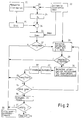
- the printer is made 4 suggestions via the input / output device, which he can follow or change by making appropriate entries.
- the measured values of the spectrometer ie the actual values
- the target values, the tolerances and the respective layer thickness / density Smax are taken from a memory.
- the differences between the measured values and the target values are formed by a subtraction 23, from which the layer thickness / density changes deltaSs at 24 are calculated.
- the existing layer thicknesses / densities Sist are calculated from the actual values. Adding Sist and deltaSs at 26 results in the setpoints for the layer thicknesses / densities Sneu. At 20, these are compared with the maximum values for the layer thicknesses / densities.
- the program is branched at 27. If the target layer thicknesses / densities Sneu are not greater than the maximum permissible layer thicknesses / densities Smax, the data corresponding to the target layer thicknesses / densities Sneu are supplied to the color control unit 3 (FIG. 1) and the ink guide elements 2 of the printing press 1 are controlled accordingly.
- the target layer thicknesses / densities Sneu are greater than the maximum permissible layer thicknesses / densities Smax
- an optimal point in the color space is calculated at 28, at which the layer thicknesses / densities are smaller than the permissible layer thicknesses / densities Smax.
- a decision is then made as to whether this color locus lies within the tolerances. If this is the case, the output of the color control data and its transmission to the color control unit 3 (FIG. 1) is again initiated in the program part 30.
- the printer input is queried. If this entry includes an expansion of the tolerances, the calculated color control data are output and transmitted after branching 34. If the printer has no new tolerances, but has entered larger values for the permissible layer thicknesses / densities, a new color location is calculated after branching 35 at 28. If this is within the tolerances, the color control data is output. If this is not the case, alternative suggestions are again calculated so that the printer has the opportunity to enter new tolerances or new permissible layer thicknesses / densities. The printer declares If there are no new tolerances or new permissible layer thicknesses / densities, then after passing through branches 34 and 35, the printer is asked at 36 whether printing should take place outside the permissible tolerances. If the printer affirms this by a corresponding input, corresponding color control data are output to the color control unit 3 after branching 37. However, if the printer does not allow printing outside the tolerances, this leads to an abort at 38.
- tolerance and tolerance range are explained with the aid of FIG. 3 using the example of a tolerance ellipsoid.
- L the origin of the coordinate system L
- a, b representing the color space according to FIG. 3
- the target value for the color to be printed is assumed.
- All actual values that lie within an ellipsoid with the semi-axes deltaL, deltaA and deltaB are tolerated. Since people tend to accept deviations in brightness as color casts, deltaL is larger than deltaA or deltaB.
- the tolerance values on which the respective print job is based depend on the print quality required in each case and can be entered by the printer.
- a "calculation tolerance” which is smaller than the tolerance specified by the printer is preferably used for the calculations within the method according to the invention .
- a first method step is explained with reference to FIG. 4.
- the color locus Eist measured with the spectrometer 9 and the target color locus Esoll are connected by a straight line, the equation of which is also shown in FIG. 4.
- deltaL, deltaa and deltab mean the differences between the coordinates of the target color location and the actual color location
- deltaS1s, deltaS2s and deltaS3s the differences in the layer thicknesses / densities of the printing inks and A a constant.
- Lambda is the independent variable that identifies the location on the straight line.
- the layer thicknesses / densities for the color location Esoll lie within the maximum permissible layer thicknesses / densities. If this is not the case, however, the printing ink is determined which, with the same change in all three printing colors, is the first to reach the maximum permissible layer thickness / density in proportion to the required change in deltaSs. This printing ink is referred to below as F1.
- the color location E1 is calculated on the connecting line between Eist and Esoll at which the printing ink F1 has reached the maximum permissible layer thickness / density.
- the following step is explained with reference to FIG. 5.
- a level of those color locations is calculated which can be achieved by changing the two remaining printing colors. This level is hatched in FIG. 5 and in other figures.
- the plane is cut with the tolerance ellipsoid. This determines the amount of color locations that match the both printing inks F2 and F3 can be achieved and are within the tolerance range. If the plane intersects the tolerance ellipsoids, a real ellipse is created. If the plane avoids the ellipsoids, the ellipse is imaginary.
- the next step in the process is to determine the point for which the necessary tolerance space becomes minimal, here the center of the ellipse. This becomes the new setpoint Es'.
- Es' is the point on the plane that would be the center point of the sectional ellipse in the case of an enlarged ellipsoid. It is always real, even with an imaginary ellipse.
- new setpoints for the layer thicknesses / densities are calculated and output, provided there is a real ellipse and the layer thicknesses / densities for Es' are not greater than Smax. If the latter is not the case, then starting from the color location E1, the printing ink is determined which, with the same change in the two printing inks F2 and F3 in proportion to their required change deltaSs, is the first to reach the maximum permissible layer thickness / density.
- the point E2 lies on the connecting line between E1 and Es' (Fig. 8).
- a plane of the color locations that could be achieved by changing the printing inks F2 and F3 was calculated, in a further method step a straight line is calculated, which is described by a further change in the printing color F3.
- This straight line is designated in Fig. 9 with S3 '.
- S3 ' By cutting the straight line S3 'with the tolerance ellipse, the amount of those color locations is determined which can be achieved with the third printing ink and which are within the tolerance range. If the straight line avoids the ellipse, see above if the intersections are imaginary, if there is an intersection, they are real.
- the point on the straight line is calculated, at which the necessary tolerance space becomes minimal - the center point of the chord formed by the straight line - and is adopted as the new setpoint Es ⁇ .
- Es ⁇ is the point that would result from a magnification of the ellipsoid as the center. It is always real, even at imaginary intersections.
- the formation of Es ⁇ is in Fig. 10 for the case that the straight line S3 'does not intersect the tolerance ellipsoids.
- the color location Es ′′′ is determined for which the layer thickness / density corresponds to the maximum permissible layer thickness / density Smax.
Landscapes
- Engineering & Computer Science (AREA)
- Quality & Reliability (AREA)
- Inking, Control Or Cleaning Of Printing Machines (AREA)
- Printing Methods (AREA)
Applications Claiming Priority (2)
| Application Number | Priority Date | Filing Date | Title |
|---|---|---|---|
| DE3812099 | 1988-04-12 | ||
| DE3812099A DE3812099C2 (de) | 1988-04-12 | 1988-04-12 | Verfahren zur Farbsteuerung einer Offsetdruckmaschine |
Publications (3)
| Publication Number | Publication Date |
|---|---|
| EP0337148A2 true EP0337148A2 (fr) | 1989-10-18 |
| EP0337148A3 EP0337148A3 (en) | 1990-08-22 |
| EP0337148B1 EP0337148B1 (fr) | 1994-06-15 |
Family
ID=6351790
Family Applications (1)
| Application Number | Title | Priority Date | Filing Date |
|---|---|---|---|
| EP89104677A Expired - Lifetime EP0337148B1 (fr) | 1988-04-12 | 1989-03-16 | Procédé de commande de l'encrage d'une machine d'impression |
Country Status (5)
| Country | Link |
|---|---|
| US (1) | US5122977A (fr) |
| EP (1) | EP0337148B1 (fr) |
| JP (1) | JPH074924B2 (fr) |
| CA (1) | CA1328197C (fr) |
| DE (2) | DE3812099C2 (fr) |
Cited By (5)
| Publication number | Priority date | Publication date | Assignee | Title |
|---|---|---|---|---|
| FR2643017A1 (fr) * | 1989-02-10 | 1990-08-17 | Heidelberger Druckmasch Ag | Procede de reglage de la coloration de produits imprimes |
| EP0585740A1 (fr) * | 1992-09-02 | 1994-03-09 | MAN Roland Druckmaschinen AG | Méthode pour la commande du processus d'impression dans une presse d'imprimerie à cliché trame en particulier une machine à imprimer offset à feuilles |
| EP0600335A1 (fr) * | 1992-11-28 | 1994-06-08 | Heidelberger Druckmaschinen Aktiengesellschaft | Méthode pour zonalement commander/régler l'encrage dans une machine d'impression |
| DE4104537C2 (de) * | 1991-02-14 | 1999-05-12 | Roland Man Druckmasch | Verfahren zur Steuerung einer Farbführung einer Offset-Druckmaschine |
| WO2010022998A1 (fr) * | 2008-08-23 | 2010-03-04 | Manroland Ag | Système de commande d’une machine d’impression |
Families Citing this family (40)
| Publication number | Priority date | Publication date | Assignee | Title |
|---|---|---|---|---|
| DE3913382C2 (de) * | 1989-04-24 | 1995-12-14 | Heidelberger Druckmasch Ag | Verfahren zur Steuerung der Farbführung einer Druckmaschine |
| DE4005558A1 (de) * | 1990-02-22 | 1991-09-19 | Roland Man Druckmasch | Verfahren zur prozessdiagnose einer rotationsdruckmaschine anhand von remissionen von vollton- und rastertonfeldern |
| JPH06510116A (ja) * | 1991-04-17 | 1994-11-10 | ベミス・マニファクチュアリング・カンパニー | データ点解析の方法及び装置 |
| CH686357A5 (fr) * | 1991-05-06 | 1996-03-15 | Bobst Sa | Dispositif de lecture d'une marque imprimée sur un élément en plaque ou en bande. |
| DE4131303B4 (de) * | 1991-09-20 | 2005-03-10 | Heidelberger Druckmasch Ag | Verfahren und Vorrichtung zur optoelektronischen Bildabtastung für den Druckprozeß einer Offset-Druckmaschine |
| US5841955A (en) * | 1991-12-02 | 1998-11-24 | Goss Graphic Systems, Inc. | Control system for a printing press |
| US5224421A (en) * | 1992-04-28 | 1993-07-06 | Heidelberg Harris, Inc. | Method for color adjustment and control in a printing press |
| US5357448A (en) * | 1993-02-02 | 1994-10-18 | Quad/Tech, Inc. | Method and apparatus for controlling the printing of an image having a plurality of printed colors |
| FI95888C (fi) * | 1993-04-26 | 1996-04-10 | Valtion Teknillinen | Menetelmä painatuksen laadun valvomiseksi |
| CA2107431A1 (fr) * | 1993-09-30 | 1995-03-31 | Arthur L. Rosbottom | Appareil servant a l'evaluation de donnees sur la couleur, et methode connexe |
| JPH09507040A (ja) * | 1993-10-28 | 1997-07-15 | ペレッタ グラフィクス コーポレーション | インク濃度を保持するためのシステム |
| DE4415486C2 (de) * | 1994-05-03 | 1998-06-04 | Heidelberger Druckmasch Ag | Verfahren zur Bestimmung der zulässigen Toleranzen für die Steuerung oder Regelung der Farbgebung an einer Druckmaschine |
| DE19506425B4 (de) * | 1995-02-24 | 2004-11-18 | Heidelberger Druckmaschinen Ag | Offsetdruckverfahren |
| US5812705A (en) * | 1995-02-28 | 1998-09-22 | Goss Graphic Systems, Inc. | Device for automatically aligning a production copy image with a reference copy image in a printing press control system |
| DE29507302U1 (de) * | 1995-05-05 | 1995-06-22 | MAN Roland Druckmaschinen AG, 63075 Offenbach | Rotationsdruckmaschine |
| US5767980A (en) * | 1995-06-20 | 1998-06-16 | Goss Graphic Systems, Inc. | Video based color sensing device for a printing press control system |
| US5805280A (en) * | 1995-09-28 | 1998-09-08 | Goss Graphic Systems, Inc. | Control system for a printing press |
| US5903712A (en) * | 1995-10-05 | 1999-05-11 | Goss Graphic Systems, Inc. | Ink separation device for printing press ink feed control |
| US6043909A (en) | 1996-02-26 | 2000-03-28 | Imagicolor Corporation | System for distributing and controlling color reproduction at multiple sites |
| US6459425B1 (en) | 1997-08-25 | 2002-10-01 | Richard A. Holub | System for automatic color calibration |
| DE19703129B4 (de) * | 1997-01-29 | 2014-08-21 | Heidelberger Druckmaschinen Ag | Verfahren zur Bewertung der Qualität eines im Mehrfarbendruck auf einem Bedruckstoff erzeugten Druckbildes |
| DE59708489D1 (de) * | 1997-02-19 | 2002-11-21 | Baldwin Germany Gmbh | Vorrichtung und Verfahren zur Durchführung von qualitätsmanagement |
| DE19749066A1 (de) * | 1997-11-06 | 1999-05-12 | Heidelberger Druckmasch Ag | Verfahren zur Regelung des Farbauftrages bei einer Druckmaschine |
| DE19749063A1 (de) * | 1997-11-06 | 1999-05-12 | Heidelberger Druckmasch Ag | Verfahren zur Gewinnung von Farbmeßwerten |
| BR0207825A (pt) * | 2001-03-02 | 2004-04-27 | Ackley Martinez Company Dba Mg | Sistema e método de ajuste de impressão |
| CN1537055A (zh) * | 2001-07-30 | 2004-10-13 | 阿克利・马丁内斯公司Dba Mgi工作 | 色彩管理处理系统和方法 |
| JP2004536731A (ja) | 2001-07-30 | 2004-12-09 | ジ アックレイ マルティネス カンパニー デイビーエイ エムジーアイ ステューディオ | システム混合を補償するシステムと方法 |
| JP2003311933A (ja) * | 2002-04-24 | 2003-11-06 | Dainippon Screen Mfg Co Ltd | パッチ測定装置およびそれを組み込んだ印刷装置 |
| JP4216001B2 (ja) * | 2002-05-21 | 2009-01-28 | 大日本スクリーン製造株式会社 | 印刷機のインキ供給方法および印刷機のインキ供給装置 |
| US6938550B2 (en) * | 2002-10-31 | 2005-09-06 | R. R. Donnelley & Sons, Co. | System and method for print screen tonal control and compensation |
| US7017492B2 (en) * | 2003-03-10 | 2006-03-28 | Quad/Tech, Inc. | Coordinating the functioning of a color control system and a defect detection system for a printing press |
| JP4484541B2 (ja) * | 2004-02-20 | 2010-06-16 | 大日本スクリーン製造株式会社 | 印刷機のインキ供給方法 |
| US7605959B2 (en) | 2005-01-05 | 2009-10-20 | The Ackley Martinez Company | System and method of color image transformation |
| US7077064B1 (en) * | 2005-04-19 | 2006-07-18 | Sun Chemical Corporation | Methods for measurement and control of ink concentration and film thickness |
| DE102006014657B4 (de) | 2006-03-28 | 2008-11-20 | Koenig & Bauer Aktiengesellschaft | Verfahren zur Farbregelung einer Druckmaschine |
| JP5022682B2 (ja) * | 2006-11-30 | 2012-09-12 | リョービ株式会社 | カラー印刷機の印刷画像品質管理方法及び印刷画像品質管理装置 |
| JP2009000884A (ja) * | 2007-06-21 | 2009-01-08 | Komori Corp | 印刷機の印刷品質管理方法及び装置 |
| EP2439071A1 (fr) | 2010-10-11 | 2012-04-11 | KBA-NotaSys SA | Motif de contrôle des couleurs pour la mesure optique de couleurs imprimées sur un substrat de type feuille ou toile à l'aide d'une presse d'impression multicolore et utilisations correspondantes |
| US11458724B2 (en) | 2016-09-13 | 2022-10-04 | Advanced Vision Technology (A.V.T.) Ltd. | System and method for controlling color characteristics of a printed image |
| IL254078A0 (en) | 2017-08-21 | 2017-09-28 | Advanced Vision Tech A V T Ltd | Method and system for creating images for testing |
Family Cites Families (12)
| Publication number | Priority date | Publication date | Assignee | Title |
|---|---|---|---|---|
| JPS5698634A (en) * | 1980-01-09 | 1981-08-08 | Dainippon Printing Co Ltd | Printed matter testing device |
| DE3127381A1 (de) * | 1981-07-10 | 1983-01-27 | Salvat Editores, S.A., Barcelona | Messorgane fuer im geschlossenen kreis arbeitende systeme zur ueberwachung und korrektur des drucks bei offset-druckmaschinen |
| DE3209483A1 (de) * | 1982-03-16 | 1983-09-29 | Windmöller & Hölscher, 4540 Lengerich | Verfahren zum automatischen einstellen der von flexodruckmaschinen fuer den vierfarbendruck ausgedrucktenfarben |
| EP0114914B1 (fr) * | 1983-01-29 | 1987-04-22 | M.A.N.-ROLAND Druckmaschinen Aktiengesellschaft | Dispositif pour détecter et évaluer des bandes de mesure colorimétriques sur une feuille d'impression |
| US4706206A (en) * | 1983-09-20 | 1987-11-10 | Kollmorgen Technologies Corporation | Color printing control using halftone control areas |
| DE3468367D1 (en) * | 1983-11-04 | 1988-02-11 | Gretag Ag | Method and device for judging the printing quality of a printed object, preferably printed by an offset printing machine, and offset printing machine provided with such a device |
| DE3468650D1 (en) * | 1983-11-04 | 1988-02-18 | Gretag Ag | Method and device for rating the printing quality and/or controlling the ink supply in an offset printing machine, and offset printing machine with such a device |
| DD227094B5 (de) * | 1984-10-04 | 1996-02-22 | Roland Man Druckmasch | Verfahren zur farbmetrischen Auswertung von Druckprodukten |
| DE3666554D1 (en) * | 1985-12-10 | 1989-11-30 | Heidelberger Druckmasch Ag | Process for controlling the application of colours in a printing machine, printing device equipped therewith and measuring device for such a printing device |
| DE3626423A1 (de) * | 1986-08-05 | 1988-02-11 | Deutsche Forsch Druck Reprod | Verfahren und vorrichtung zur beeinflussung der farblichen erscheinung einer farbflaeche bei einem druckvorgang |
| US4967379A (en) * | 1987-12-16 | 1990-10-30 | Gretag Aktiengesellschaft | Process for the ink control or regulation of a printing machine by comparing desired color to obtainable color data |
| DE58901780D1 (de) * | 1988-01-14 | 1992-08-13 | Gretag Ag | Verfahren und vorrichtung zur farbregelung einer druckmaschine. |
-
1988
- 1988-04-12 DE DE3812099A patent/DE3812099C2/de not_active Expired - Fee Related
-
1989
- 1989-03-09 CA CA000593276A patent/CA1328197C/fr not_active Expired - Fee Related
- 1989-03-16 DE DE58907872T patent/DE58907872D1/de not_active Expired - Fee Related
- 1989-03-16 EP EP89104677A patent/EP0337148B1/fr not_active Expired - Lifetime
- 1989-04-12 JP JP1090903A patent/JPH074924B2/ja not_active Expired - Lifetime
-
1991
- 1991-05-28 US US07/708,113 patent/US5122977A/en not_active Expired - Lifetime
Cited By (9)
| Publication number | Priority date | Publication date | Assignee | Title |
|---|---|---|---|---|
| FR2643017A1 (fr) * | 1989-02-10 | 1990-08-17 | Heidelberger Druckmasch Ag | Procede de reglage de la coloration de produits imprimes |
| GB2229019A (en) * | 1989-02-10 | 1990-09-12 | Heidelberger Druckmasch Ag | Controlling printing ink values |
| US5089977A (en) * | 1989-02-10 | 1992-02-18 | Heidelberger Druckmaschinen Ag | Process for controlling the inking of printed products and apparatus for performing the process |
| GB2229019B (en) * | 1989-02-10 | 1993-04-07 | Heidelberger Druckmasch Ag | Process for the control of the inking of printed products |
| DE4104537C2 (de) * | 1991-02-14 | 1999-05-12 | Roland Man Druckmasch | Verfahren zur Steuerung einer Farbführung einer Offset-Druckmaschine |
| EP0585740A1 (fr) * | 1992-09-02 | 1994-03-09 | MAN Roland Druckmaschinen AG | Méthode pour la commande du processus d'impression dans une presse d'imprimerie à cliché trame en particulier une machine à imprimer offset à feuilles |
| EP0600335A1 (fr) * | 1992-11-28 | 1994-06-08 | Heidelberger Druckmaschinen Aktiengesellschaft | Méthode pour zonalement commander/régler l'encrage dans une machine d'impression |
| US5460090A (en) * | 1992-11-28 | 1995-10-24 | Heidelberger Druckmaschinen Ag | Method and device for zonally controlling and regulating inking in a printing machine |
| WO2010022998A1 (fr) * | 2008-08-23 | 2010-03-04 | Manroland Ag | Système de commande d’une machine d’impression |
Also Published As
| Publication number | Publication date |
|---|---|
| JPH01314171A (ja) | 1989-12-19 |
| EP0337148B1 (fr) | 1994-06-15 |
| JPH074924B2 (ja) | 1995-01-25 |
| DE3812099A1 (de) | 1989-10-26 |
| US5122977A (en) | 1992-06-16 |
| CA1328197C (fr) | 1994-04-05 |
| DE58907872D1 (de) | 1994-07-21 |
| EP0337148A3 (en) | 1990-08-22 |
| DE3812099C2 (de) | 1995-01-26 |
Similar Documents
| Publication | Publication Date | Title |
|---|---|---|
| EP0337148B1 (fr) | Procédé de commande de l'encrage d'une machine d'impression | |
| EP0196431B1 (fr) | Procédé, dispositif de réglage et moyens auxiliaires pour l'obtention d'un résultat d'impression uniforme au moyen d'une machine d'impression offset polychrome fonctionnant suivant le procédé de similigravure | |
| EP0321402B1 (fr) | Procédé de commande ou du réglage de l'encrage d'une presse à imprimer | |
| EP0255586B1 (fr) | Procédé et dispositif pour influencer l'encrage d'une surface encrée dans une machine à imprimer | |
| CH650451A5 (de) | Vorrichtung zur vorbereitung einer druckpresse. | |
| DE4100534C1 (fr) | ||
| DE3913382C2 (de) | Verfahren zur Steuerung der Farbführung einer Druckmaschine | |
| DE19515499C2 (de) | Verfahren zur simultanen Mehrfarbregelung beim Drucken | |
| EP0585740B1 (fr) | Méthode pour la commande du processus d'impression dans une presse d'imprimerie à cliché trame en particulier une machine à imprimer offset à feuilles | |
| EP0825023A2 (fr) | Procédé pour déterminer des données de reglage pour la commande d'une machine à imprimer | |
| EP0505323B2 (fr) | Procédé pour le réglage des grandeurs des points de trame pour une presse rotative à imprimer offset | |
| DE3543444A1 (de) | Verfahren und regelvorrichtung zur erzielung eines gleichfoermigen druckresultats an einer autotypisch arbeitenden mehrfarbendruckmaschine | |
| DE4240077C2 (de) | Verfahren zur zonalen Steuerung/Regelung der Farbführung in einer Druckmaschine | |
| EP0421003B1 (fr) | Méthode pour contrôler l'apport d'encre dans une machine d'impression | |
| EP0522301B1 (fr) | Procédé de surveillance et de réglage du processus d'impression, en particulier dans les machines à imprimer en offset | |
| DE3708652A1 (de) | Verfahren zur erzielung einer vorgegebenen farbdichte beim drucken mit einer offset-druckmaschine | |
| DE69911352T2 (de) | Verfahren und Vorrichtung zum Korrigieren der Farbzonenschraubenstellung in einer Druckmaschine | |
| DE3440706C2 (fr) | ||
| DE4104537C2 (de) | Verfahren zur Steuerung einer Farbführung einer Offset-Druckmaschine | |
| DE69014812T2 (de) | Farb- und Wassermehrfachkurven für Druckmaschinen. | |
| EP0282446B1 (fr) | Procédé de réglage continu de l'encrage en impression en creux ou flexographique et machine correspondante | |
| DE102004011239C5 (de) | Verfahren zur automatischen Farbvoreinstellung an mindestens einem Farbwerk einer Druckmaschine | |
| DE10359382B4 (de) | Verfahren und Vorrichtung zur Lageregelung von Baugruppen einer Druckmaschine | |
| DE102019134917A1 (de) | Verfahren zur Verbesserung der Ansteuerung eines Aktuators und Vorrichtung zum Durchführen des Verfahrens | |
| DE4410228C2 (de) | Verfahren und Vorrichtung zur freiwählbaren Ersetzung des Unbuntanteils im Mehrfarbendruck durch die Druckfarbe Schwarz |
Legal Events
| Date | Code | Title | Description |
|---|---|---|---|
| PUAI | Public reference made under article 153(3) epc to a published international application that has entered the european phase |
Free format text: ORIGINAL CODE: 0009012 |
|
| 17P | Request for examination filed |
Effective date: 19890316 |
|
| AK | Designated contracting states |
Kind code of ref document: A2 Designated state(s): CH DE FR GB IT LI SE |
|
| PUAL | Search report despatched |
Free format text: ORIGINAL CODE: 0009013 |
|
| AK | Designated contracting states |
Kind code of ref document: A3 Designated state(s): CH DE FR GB IT LI SE |
|
| 17Q | First examination report despatched |
Effective date: 19920527 |
|
| GRAA | (expected) grant |
Free format text: ORIGINAL CODE: 0009210 |
|
| AK | Designated contracting states |
Kind code of ref document: B1 Designated state(s): CH DE FR GB IT LI SE |
|
| REF | Corresponds to: |
Ref document number: 58907872 Country of ref document: DE Date of ref document: 19940721 |
|
| ET | Fr: translation filed | ||
| ITF | It: translation for a ep patent filed | ||
| GBT | Gb: translation of ep patent filed (gb section 77(6)(a)/1977) |
Effective date: 19940831 |
|
| EAL | Se: european patent in force in sweden |
Ref document number: 89104677.3 |
|
| PLBE | No opposition filed within time limit |
Free format text: ORIGINAL CODE: 0009261 |
|
| STAA | Information on the status of an ep patent application or granted ep patent |
Free format text: STATUS: NO OPPOSITION FILED WITHIN TIME LIMIT |
|
| 26N | No opposition filed | ||
| PGFP | Annual fee paid to national office [announced via postgrant information from national office to epo] |
Ref country code: SE Payment date: 19960304 Year of fee payment: 8 |
|
| PGFP | Annual fee paid to national office [announced via postgrant information from national office to epo] |
Ref country code: GB Payment date: 19970220 Year of fee payment: 9 |
|
| PG25 | Lapsed in a contracting state [announced via postgrant information from national office to epo] |
Ref country code: SE Effective date: 19970317 |
|
| EUG | Se: european patent has lapsed |
Ref document number: 89104677.3 |
|
| PG25 | Lapsed in a contracting state [announced via postgrant information from national office to epo] |
Ref country code: GB Free format text: LAPSE BECAUSE OF NON-PAYMENT OF DUE FEES Effective date: 19980316 |
|
| GBPC | Gb: european patent ceased through non-payment of renewal fee |
Effective date: 19980316 |
|
| PGFP | Annual fee paid to national office [announced via postgrant information from national office to epo] |
Ref country code: FR Payment date: 20010321 Year of fee payment: 13 |
|
| PG25 | Lapsed in a contracting state [announced via postgrant information from national office to epo] |
Ref country code: FR Free format text: LAPSE BECAUSE OF NON-PAYMENT OF DUE FEES Effective date: 20021129 |
|
| REG | Reference to a national code |
Ref country code: FR Ref legal event code: ST |
|
| PG25 | Lapsed in a contracting state [announced via postgrant information from national office to epo] |
Ref country code: IT Free format text: LAPSE BECAUSE OF NON-PAYMENT OF DUE FEES;WARNING: LAPSES OF ITALIAN PATENTS WITH EFFECTIVE DATE BEFORE 2007 MAY HAVE OCCURRED AT ANY TIME BEFORE 2007. THE CORRECT EFFECTIVE DATE MAY BE DIFFERENT FROM THE ONE RECORDED. Effective date: 20050316 |
|
| PGFP | Annual fee paid to national office [announced via postgrant information from national office to epo] |
Ref country code: CH Payment date: 20060406 Year of fee payment: 18 |
|
| PGFP | Annual fee paid to national office [announced via postgrant information from national office to epo] |
Ref country code: DE Payment date: 20070326 Year of fee payment: 19 |
|
| REG | Reference to a national code |
Ref country code: CH Ref legal event code: PL |
|
| PG25 | Lapsed in a contracting state [announced via postgrant information from national office to epo] |
Ref country code: CH Free format text: LAPSE BECAUSE OF NON-PAYMENT OF DUE FEES Effective date: 20070331 Ref country code: LI Free format text: LAPSE BECAUSE OF NON-PAYMENT OF DUE FEES Effective date: 20070331 |
|
| PG25 | Lapsed in a contracting state [announced via postgrant information from national office to epo] |
Ref country code: DE Free format text: LAPSE BECAUSE OF NON-PAYMENT OF DUE FEES Effective date: 20081001 |