EP0337290A2 - Collecteur pour un moteur électrique ainsi que son armature - Google Patents
Collecteur pour un moteur électrique ainsi que son armature Download PDFInfo
- Publication number
- EP0337290A2 EP0337290A2 EP89106040A EP89106040A EP0337290A2 EP 0337290 A2 EP0337290 A2 EP 0337290A2 EP 89106040 A EP89106040 A EP 89106040A EP 89106040 A EP89106040 A EP 89106040A EP 0337290 A2 EP0337290 A2 EP 0337290A2
- Authority
- EP
- European Patent Office
- Prior art keywords
- reinforcement according
- reinforcement
- anchoring
- collector
- ring
- Prior art date
- Legal status (The legal status is an assumption and is not a legal conclusion. Google has not performed a legal analysis and makes no representation as to the accuracy of the status listed.)
- Withdrawn
Links
Images


Classifications
-
- H—ELECTRICITY
- H01—ELECTRIC ELEMENTS
- H01R—ELECTRICALLY-CONDUCTIVE CONNECTIONS; STRUCTURAL ASSOCIATIONS OF A PLURALITY OF MUTUALLY-INSULATED ELECTRICAL CONNECTING ELEMENTS; COUPLING DEVICES; CURRENT COLLECTORS
- H01R39/00—Rotary current collectors, distributors or interrupters
- H01R39/02—Details for dynamo electric machines
- H01R39/14—Fastenings of commutators or slip-rings to shafts
Definitions
- the invention relates to a collector for an electric motor according to the preamble of claim 1 and a reinforcement according to the preamble of claim 2.
- Electric collector motors are used in everyday use to a very large and still growing extent and are subject to strong price pressure as mass articles. Nevertheless, the requirements for such electric motors in terms of the desired performance, the thermal and mechanical load capacity are very high. The robustness of the collectors is particularly important for these load capacities and the service life of the motors.
- collectors for higher requirements In addition to collectors for a low to medium power and load range, the slats of which are held only by an insulating plastic casting compound, there are collectors for higher requirements with special, stronger reinforcement rings.
- metallic reinforcement rings that are insulated from the copper lamellae by means of mica inserts.
- glass rovings as reinforcement rings, in which, however, it is complex and cumbersome to bring the reinforcement ring into its predetermined position and to hold it in this position when the collector is potted. Accordingly, collectors for higher requirements are more expensive because of the special manufacturing outlay again the production series reduced and therefore the unit costs increased again.
- the object of the invention is to provide a collector or a reinforcement system in which a significantly reduced workload and simplified handling in production are to be provided for high mechanical and thermal strength.
- this object is achieved by a collector according to the preamble of claim 1 based on the characterizing features of claim 1. Furthermore, the task is solved by a reinforcement ring according to the preamble of claim 2 by the characterizing features of claim 2.
- the reinforcement ring according to the invention has a firm, precise shape which enables a suitable, positive and non-positive contact between the reinforcement ring and lamella.
- the reinforcement ring does not come into play only through an intermediate layer of sealing compound, rather it is in direct contact. This already suppresses deformations, cracks or loosening movements, which, once they occur, exacerbate the harmful stress effects.
- the closed inner ring with anchoring projections to the outside can also be designed regardless of the cross-section available for undercuts. It is therefore not necessary to dimension the reinforcement ring in consideration of a dovetail shape or the like undercut.
- the armoring ring is still able to absorb special loads in motor production, for example if the motor winding is connected to the collector by hot stacking, with temperatures of up to 600 ° C occurring.
- pressing the collector onto an armature shaft represents a special load, which can be easily absorbed by a reinforcement ring.
- the decisive advantages of this construction are in the fact that the shape of the reinforcement ring makes it possible to introduce them into the free interior of the previously arranged copper lamellae and thereby to hook them up.
- the complete set of copper lamellas and the reinforcement ring can be connected to one another in a positive and non-positive manner.
- the subsequent pressing or casting then also serves to fix the parts which are connected to one another in a load-bearing manner.
- the reinforcement rings can be completed to form reinforcements in which the rings are connected with bushings, so that already during assembly, the collector lamellae not only to one another, but also to an already prefabricated inner surface of the Are adjusted. Subsequent pressing operations only provide fixation and backfilling of the collector. However, the socket already provides the press-on surfaces for subsequent press mounting of the collector on a motor shaft.
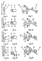
- a reinforcement ring generally designated 1
- Its shape is largely determined by the shape of copper lamellae 2 of a collector to be created herewith, which has an inner web 3 on the underside as an anchoring web, in which a dovetail-shaped recess 4 with oblique undercut surfaces 5 is worked out (see FIG. 4).
- the reinforcement ring 1 has an inner circumferential support ring 6, the cylindrical outer wall 7 of which runs inside the inner webs 3.
- the reinforcement ring 1 only projects with extensions 8 into the area of the inner webs 3.
- the anchoring extensions 8 are arranged in the circumferential direction with a uniform division grid 9 on the support ring 6 and have a rectangular profile in the front view according to FIG. 1, which is chosen such that it is set to a gap between the inner webs 3 of the collector.
- FIG. 2 In the cross-sectional profile of the reinforcement ring 1 according to FIG. 2 it can be seen that such an extension 8 has a dovetail shape which fits into the recess of the web 3. It goes without saying that other forms of closure are possible.
- the reinforcement ring engages with each of its extensions 8 in an inner web and creates a resilient, non-positive connection via the dovetail shape.
- such a ring can be inserted into the copper fins after they have been arranged in a ring in a suitable device.
- the reinforcement ring 1 is first pushed in from the front in the axial direction of the collector, the anchoring extensions being in a gap with the inner webs 3.
- the extensions 8 then come into engagement with the dovetail recesses 4 and create the desired anchoring.
- the reinforcement ring 1 shows the reinforcement ring 1 with its anchoring extensions 8 as it is arranged on an assembly tool 10 suitable for insertion, here an octagonal key.
- the reinforcement ring 1 has a poligon profile (octagonal profile) as the inner surface 11.
- a poligon profile octagonal profile
- a single reinforcement ring is shown.
- the slats are then supported several times over the length, usually two or three times.
- the reinforcement rings and the copper lamellae are formed into a one-piece unit, in which not only is it not possible that the extensions of the reinforcement ring move back out of the lamellae, but also in which gaps remaining during insertion are filled to ensure a uniform transmission of the loads from outside to inside.
- FIG. 5 shows a lamella 11 with an inner web 12 which (at least) contains a predominantly circular extension 13.
- a matching reinforcement ring 14 is in Fig. 6 and 7 (Fig. 6 is a section along line VI-VI in Fig. 7) equipped with extensions 15 which differ from the extensions 8 of the reinforcement ring 1 in that they are in adaptation have a circular arc contour at the recess 13.
- This reinforcement ring is also designed so that it can be inserted axially into the interior with sufficient play, in order then to engage the inner webs by rotating it by less than one pitch.
- the lamella can be a tube collector lamella, but can also be obtained from an extruded strand or a strip.
- the - collector lamella has an inside longitudinal web 18. These webs are cut from the end to the inside and bent inwards by a mechanical punching tool, so that spinous processes 19 result for anchoring. Only after pressing is the circumferential copper body cut into individual fins.
- a reinforcement ring 20 shown in FIGS. 9 and 10 is formed from an internal, continuous support ring 21 and anchoring projections 22 attached to it on the outside in the form of claws with anchoring cavities 23 pointing in the axial direction.
- Such a reinforcement ring is slipped over the spinous processes 19 in the axial direction and, due to the inclined surfaces on both sides, comes into play-free contact. If this system is secured by subsequent casting or pressing, the reinforcement ring is able to support the slats 16 in a particularly robust manner against axial, radial and tangential forces.
- FIG. 11 again shows a collector lamella corresponding to FIG. 8 and also provided with the same reference numerals.
- Another reinforcing ring is provided for this type of lamella according to FIGS. 12 and 13 (FIG. 12 shows a section along line XII-XII in FIG. 13).
- anchoring extensions 24 are formed as pairs of claws 25, 26 on an inner support ring 27. These carry anchoring cavities 28 on the side surfaces facing one another, which are adapted to the contour of the spinous processes 19.
- the assignment of the slats is finally fixed.
- FIG. 14 again shows a collector lamella which, irrespective of minor deviations, basically corresponds to the lamella according to FIGS. 8 and 11 and is accordingly also identified by corresponding reference numerals.
- the spinous process 19 points downwards, which makes it clear that this is about reinforcing the collector on the opposite side.
- a reinforcing ring 29 with claws 30 and anchoring cavities 31 is designed to match the anchoring ring 20 according to FIGS. 9 and 10.
- it carries spacing projections 32 projecting in the axial direction in the form of cylindrical pins attached to an inner support ring 33.
- the reinforcement ring 29 is set up from the bottom of the respective assembly and casting mold, so that the spinous processes 19 abut in the anchoring cavity 31 and a positive and non-positive connection is achieved. It goes without saying that the cylindrical shape can be replaced by other suitable designs.
- FIG. 17 shows part of a collector 34 with individual lamellae 35, which have inner webs 36 profiled on the underside with a thickened head part 37.
- a reinforcement ring 38 is positively adapted to the axial profile of the copper lamellae by receiving the inner webs 36 with their head part 37 in a positive and non-positive manner. So that the reinforcement ring 38 can perform the reinforcement functions intended for it, on the inside it has a continuous ring region 39, from which extensions 40 are directed outwards, which engage flush behind the inner lamellae and form a bridge from lamella to lamella for adjustment and pressure transmission.
- a part of a collector 41 is shown with individual lamellae 42, which have profiled inner webs 43 on the underside with a thickened head part 44.
- the inner webs 43 are undercut from the ends, so that only the head part protrudes continuously in the axial direction.
- a reinforcing ring 45 has an inner continuous ring area 46 which is connected via an outer ring area 47 via radial webs 48, so that only openings are left free through which the cut-off head part 44 of the slats 42 reaches through. The slats are thus fixed in the radial and tangential directions.
- the head parts 44 can be bent at ends 49 projecting beyond the reinforcement ring, which is possible, for example, in one operation with a caulking tool that engages in the assembled collector from the end.
- the reinforcement rings have to absorb a high mechanical load, so that the material must have good strength.
- they should not create any electrically conductive connections between the slats, so they have to consist of insulating material, at least in some areas.
- plastic materials are primarily considered, in particular glass-fiber-wrapped or resin-insulated rings, and also rings with a high proportion of glass fibers. It goes without saying that other high-strength fibers can also be used. There is also the option of using vortex sintered rings.
- the reinforcement rings described can be prefabricated mechanically and thus inexpensively and anchored extremely easily and quickly with the collector slats. This makes it possible to manufacture collectors of high strength in such a complex manner that these reinforcing rings can even be economically provided for medium loads. This creates a universal collector with the advantage of mass production, which does not have to be specified differently from the outset according to load limits.
- 21 to 26 reinforcements are shown, which not only ensure a fixed assignment of the collector lamellae to one another via an external reinforcement ring, but also simultaneously provide an internal socket in a precise concentric arrangement, with which the collector is centered and with an exact pressing dimension a motor shaft is to be applied.
- 21 and 22 show a reinforcement, designated as a whole by 50, which on the outside comprises a reinforcement ring 51 with anchoring lugs 52.
- the reinforcement ring 51 is connected via spokes 53 to a bushing 54 which extends axially on both sides of the radial plane formed by the spokes 53.
- collector lamellae Via the reinforcement ring 51, collector lamellae can be held in a central axial area, so that they have a precise position. If the ring area between the collector lamellae and the bush 54 is pressed with insulating material, a collector is obtained with a central cylindrical cavity which is delimited by a cylindrical inner surface 55 of the bush 54. The radial dimension of this cavity can be precisely specified by means of a series production with sprayable plastic, whereby the material can also be matched to the desired firm but crack-free fit. Post-processing of a potted collector by machining operations is therefore unnecessary.
- a reinforcement 56 according to FIGS. 23 and 24 differs from the previously considered reinforcement essentially in that two reinforcement rings 57, 58 which are axially spaced apart are held by a bushing 59 for better support of the collector lamellae, this bushing being of split design and wherein each socket part 60, 61 carries one of the reinforcement rings 57, 58 via spokes 62, 63. In the sense of a good coaxial alignment, the two socket parts 60, 61 are to be plugged into one another in the manner of a sleeve 64.
- FIGS. 25 and 26 which comprises an inner bushing 66 and two reinforcement rings 67 and 68
- the bushing 66 remains undivided, while the reinforcing rings are to be attached individually.
- the reinforcement rings are connected via spokes 69, 70 to inner rings 71, 72, which are pushed axially onto the bush 66 in a tight fit until they rest against one of two ring shoulders 73, 74 on the bush.
- the collector After assembling the collector lamellae, the collector is filled in the same direction by molding compound or potting compound, in which the reinforcing rings 67, 68 were attached, so that the inner rings 71, 72 received a firm contact against the ring shoulders 73, 74.
- An insulating material is again provided for the material of the bushings, which material encloses the latter as an insulating sleeve when a collector is pressed onto a motor shaft and thus meets the safety requirements for double insulation.
- a thermoplastic is preferably provided as the material, which can be controlled very well in its elastic properties and in particular also in its shrinking properties.
- a reinforcement by fibers such as glass, mineral or carbon fibers leads to considerably increased strength values, whereby short-fiber reinforcements are particularly suitable for the spraying process and provide strength increases independent of direction.
Landscapes
- Motor Or Generator Current Collectors (AREA)
Applications Claiming Priority (2)
| Application Number | Priority Date | Filing Date | Title |
|---|---|---|---|
| DE3812585 | 1988-04-15 | ||
| DE19883812585 DE3812585A1 (de) | 1987-04-16 | 1988-04-15 | Kollektor fuer einen elektromotor sowie armierungsring zu diesem |
Publications (2)
| Publication Number | Publication Date |
|---|---|
| EP0337290A2 true EP0337290A2 (fr) | 1989-10-18 |
| EP0337290A3 EP0337290A3 (fr) | 1991-08-28 |
Family
ID=6352078
Family Applications (1)
| Application Number | Title | Priority Date | Filing Date |
|---|---|---|---|
| EP19890106040 Withdrawn EP0337290A3 (fr) | 1988-04-15 | 1989-04-06 | Collecteur pour un moteur électrique ainsi que son armature |
Country Status (1)
| Country | Link |
|---|---|
| EP (1) | EP0337290A3 (fr) |
Cited By (2)
| Publication number | Priority date | Publication date | Assignee | Title |
|---|---|---|---|---|
| GB2264199A (en) * | 1992-01-22 | 1993-08-18 | Bosch Gmbh Robert | Retaining commutator segments during moulding |
| US6469414B2 (en) * | 2000-06-30 | 2002-10-22 | General Electric Company | Slip-ring mounting assembly for high-power rotary current collector system |
Family Cites Families (4)
| Publication number | Priority date | Publication date | Assignee | Title |
|---|---|---|---|---|
| DE853608C (de) * | 1941-11-16 | 1952-10-27 | Siemens Ag | Kommutator, insbesondere Pressstoffkommutator |
| US2486875A (en) * | 1945-10-30 | 1949-11-01 | Gen Electric | Commutator for dynamoelectric machines and method of making the same |
| GB1172308A (en) * | 1966-03-22 | 1969-11-26 | Fed Motor Parts Corp Proprieta | Improvements in or relating to Commutators |
| DE3443107A1 (de) * | 1984-11-27 | 1986-05-28 | Kollektor GmbH, 7812 Bad Krozingen | Kollektor |
-
1989
- 1989-04-06 EP EP19890106040 patent/EP0337290A3/fr not_active Withdrawn
Cited By (4)
| Publication number | Priority date | Publication date | Assignee | Title |
|---|---|---|---|---|
| GB2264199A (en) * | 1992-01-22 | 1993-08-18 | Bosch Gmbh Robert | Retaining commutator segments during moulding |
| GB2264199B (en) * | 1992-01-22 | 1996-02-14 | Bosch Gmbh Robert | A commutator for electric machines and a method of manufacturing a commutator |
| ES2083899A2 (es) * | 1992-01-22 | 1996-04-16 | Bosch Gmbh Robert | Conmutador para maquinas electricas y procedimiento para su fabricacion. |
| US6469414B2 (en) * | 2000-06-30 | 2002-10-22 | General Electric Company | Slip-ring mounting assembly for high-power rotary current collector system |
Also Published As
| Publication number | Publication date |
|---|---|
| EP0337290A3 (fr) | 1991-08-28 |
Similar Documents
| Publication | Publication Date | Title |
|---|---|---|
| DE2838405C3 (de) | Verfahren zur herstellung eines Ankers für einen Elektromotor und Gussform zur Durchfuerung des Verfahrens | |
| DE68912170T2 (de) | Eine Verbundstruktur aufweisender Körper für Antriebsgelenke und Verfahren zu dessen Herstellung. | |
| DE69411654T2 (de) | Verfahren zur Herstellung eines Gewindespindels aus synthetischen Kunststoff mit einem rohrartigen Kern | |
| WO2019166334A1 (fr) | Machine électrique et véhicule comprenant une telle machine | |
| DE102017222610A1 (de) | Rotor sowie Verfahren zum Herstellen eines Rotors | |
| EP2602496A1 (fr) | Liaison entre deux pièces et procédé de liaison de deux pièces | |
| DE602004007333T2 (de) | Verfahren zum Herstellen eines Ankers für eine elektrische Maschine und Anker hergestellt mit dem Verfahren | |
| DE3812585C2 (fr) | ||
| EP0693230B1 (fr) | Bague d'armature pour corps tournants | |
| EP0043968A1 (fr) | Profilé composite, notamment pour fenêtres, portes ou similaires | |
| EP0337290A2 (fr) | Collecteur pour un moteur électrique ainsi que son armature | |
| DE4015705C2 (de) | Kollektor für einen Elektromotor oder -generator | |
| DE4302759C2 (de) | Kollektor mit Armierungsring | |
| DE102017222615A1 (de) | Rotor sowie Verfahren zum Herstellen eines Rotors | |
| DE69703838T2 (de) | Gewickelter rotorhühlkörper für einen elektrischen motor | |
| DE3443107A1 (de) | Kollektor | |
| EP4080072A1 (fr) | Noyau d'arbre et arbre formé avec celui-ci | |
| EP2206206B1 (fr) | Procédé de fabrication d'une baque de commutateur pour le commutateur rotatif d'une machine électrique ainsi qu'une machine électrique | |
| DE2825963B2 (de) | Verfahren zur Herstellung einer Wand mit einer öffnung sowie einer dafür bestimmten Tür oder Klappe | |
| DE2351615C2 (de) | Abstandshalter für gasisolierte Hochspannungskabel | |
| DE4026929A1 (de) | Kollektor fuer einen elektromotor oder -generator | |
| EP0243640B1 (fr) | Collecteur | |
| EP0524393B1 (fr) | Méthode de fabrication d'un collecteur et appareil pour exécuter la méthode | |
| DE1155528B (de) | In einer Pressform hergestellter Kollektor fuer elektrische Maschinen und Verfahren zu seiner Herstellung | |
| WO1995014319A1 (fr) | Commutateur et son procede de fabrication |
Legal Events
| Date | Code | Title | Description |
|---|---|---|---|
| PUAI | Public reference made under article 153(3) epc to a published international application that has entered the european phase |
Free format text: ORIGINAL CODE: 0009012 |
|
| AK | Designated contracting states |
Kind code of ref document: A2 Designated state(s): ES GB IT |
|
| PUAL | Search report despatched |
Free format text: ORIGINAL CODE: 0009013 |
|
| AK | Designated contracting states |
Kind code of ref document: A3 Designated state(s): ES GB IT |
|
| STAA | Information on the status of an ep patent application or granted ep patent |
Free format text: STATUS: THE APPLICATION IS DEEMED TO BE WITHDRAWN |
|
| 18D | Application deemed to be withdrawn |
Effective date: 19920229 |