EP0337648A2 - Verfahren zum kontinuierlichen Verstärken von flexiblen lamellierten Lagern - Google Patents
Verfahren zum kontinuierlichen Verstärken von flexiblen lamellierten Lagern Download PDFInfo
- Publication number
- EP0337648A2 EP0337648A2 EP89303349A EP89303349A EP0337648A2 EP 0337648 A2 EP0337648 A2 EP 0337648A2 EP 89303349 A EP89303349 A EP 89303349A EP 89303349 A EP89303349 A EP 89303349A EP 0337648 A2 EP0337648 A2 EP 0337648A2
- Authority
- EP
- European Patent Office
- Prior art keywords
- laminate
- reinforcement
- layers
- ring
- conical member
- Prior art date
- Legal status (The legal status is an assumption and is not a legal conclusion. Google has not performed a legal analysis and makes no representation as to the accuracy of the status listed.)
- Withdrawn
Links
Images


Classifications
-
- B—PERFORMING OPERATIONS; TRANSPORTING
- B32—LAYERED PRODUCTS
- B32B—LAYERED PRODUCTS, i.e. PRODUCTS BUILT-UP OF STRATA OF FLAT OR NON-FLAT, e.g. CELLULAR OR HONEYCOMB, FORM
- B32B25/00—Layered products comprising a layer of natural or synthetic rubber
- B32B25/10—Layered products comprising a layer of natural or synthetic rubber next to a fibrous or filamentary layer
-
- B—PERFORMING OPERATIONS; TRANSPORTING
- B29—WORKING OF PLASTICS; WORKING OF SUBSTANCES IN A PLASTIC STATE IN GENERAL
- B29C—SHAPING OR JOINING OF PLASTICS; SHAPING OF MATERIAL IN A PLASTIC STATE, NOT OTHERWISE PROVIDED FOR; AFTER-TREATMENT OF THE SHAPED PRODUCTS, e.g. REPAIRING
- B29C43/00—Compression moulding, i.e. applying external pressure to flow the moulding material; Apparatus therefor
- B29C43/02—Compression moulding, i.e. applying external pressure to flow the moulding material; Apparatus therefor of articles of definite length, i.e. discrete articles
- B29C43/20—Making multilayered or multicoloured articles
- B29C43/203—Making multilayered articles
-
- B—PERFORMING OPERATIONS; TRANSPORTING
- B29—WORKING OF PLASTICS; WORKING OF SUBSTANCES IN A PLASTIC STATE IN GENERAL
- B29C—SHAPING OR JOINING OF PLASTICS; SHAPING OF MATERIAL IN A PLASTIC STATE, NOT OTHERWISE PROVIDED FOR; AFTER-TREATMENT OF THE SHAPED PRODUCTS, e.g. REPAIRING
- B29C70/00—Shaping composites, i.e. plastics material comprising reinforcements, fillers or preformed parts, e.g. inserts
- B29C70/04—Shaping composites, i.e. plastics material comprising reinforcements, fillers or preformed parts, e.g. inserts comprising reinforcements only, e.g. self-reinforcing plastics
- B29C70/28—Shaping operations therefor
- B29C70/30—Shaping by lay-up, i.e. applying fibres, tape or broadsheet on a mould, former or core; Shaping by spray-up, i.e. spraying of fibres on a mould, former or core
- B29C70/34—Shaping by lay-up, i.e. applying fibres, tape or broadsheet on a mould, former or core; Shaping by spray-up, i.e. spraying of fibres on a mould, former or core and shaping or impregnating by compression, i.e. combined with compressing after the lay-up operation
- B29C70/347—Shaping by lay-up, i.e. applying fibres, tape or broadsheet on a mould, former or core; Shaping by spray-up, i.e. spraying of fibres on a mould, former or core and shaping or impregnating by compression, i.e. combined with compressing after the lay-up operation combined with compressing after the winding of lay-ups having a non-circular cross-section, e.g. flat spiral windings
-
- B—PERFORMING OPERATIONS; TRANSPORTING
- B29—WORKING OF PLASTICS; WORKING OF SUBSTANCES IN A PLASTIC STATE IN GENERAL
- B29C—SHAPING OR JOINING OF PLASTICS; SHAPING OF MATERIAL IN A PLASTIC STATE, NOT OTHERWISE PROVIDED FOR; AFTER-TREATMENT OF THE SHAPED PRODUCTS, e.g. REPAIRING
- B29C70/00—Shaping composites, i.e. plastics material comprising reinforcements, fillers or preformed parts, e.g. inserts
- B29C70/04—Shaping composites, i.e. plastics material comprising reinforcements, fillers or preformed parts, e.g. inserts comprising reinforcements only, e.g. self-reinforcing plastics
- B29C70/28—Shaping operations therefor
- B29C70/40—Shaping or impregnating by compression not applied
- B29C70/42—Shaping or impregnating by compression not applied for producing articles of definite length, i.e. discrete articles
- B29C70/46—Shaping or impregnating by compression not applied for producing articles of definite length, i.e. discrete articles using matched moulds, e.g. for deforming sheet moulding compounds [SMC] or prepregs
-
- B—PERFORMING OPERATIONS; TRANSPORTING
- B29—WORKING OF PLASTICS; WORKING OF SUBSTANCES IN A PLASTIC STATE IN GENERAL
- B29C—SHAPING OR JOINING OF PLASTICS; SHAPING OF MATERIAL IN A PLASTIC STATE, NOT OTHERWISE PROVIDED FOR; AFTER-TREATMENT OF THE SHAPED PRODUCTS, e.g. REPAIRING
- B29C70/00—Shaping composites, i.e. plastics material comprising reinforcements, fillers or preformed parts, e.g. inserts
- B29C70/68—Shaping composites, i.e. plastics material comprising reinforcements, fillers or preformed parts, e.g. inserts by incorporating or moulding on preformed parts, e.g. inserts or layers, e.g. foam blocks
- B29C70/84—Shaping composites, i.e. plastics material comprising reinforcements, fillers or preformed parts, e.g. inserts by incorporating or moulding on preformed parts, e.g. inserts or layers, e.g. foam blocks by moulding material on preformed parts to be joined
-
- B—PERFORMING OPERATIONS; TRANSPORTING
- B32—LAYERED PRODUCTS
- B32B—LAYERED PRODUCTS, i.e. PRODUCTS BUILT-UP OF STRATA OF FLAT OR NON-FLAT, e.g. CELLULAR OR HONEYCOMB, FORM
- B32B25/00—Layered products comprising a layer of natural or synthetic rubber
- B32B25/12—Layered products comprising a layer of natural or synthetic rubber comprising natural rubber
-
- B—PERFORMING OPERATIONS; TRANSPORTING
- B32—LAYERED PRODUCTS
- B32B—LAYERED PRODUCTS, i.e. PRODUCTS BUILT-UP OF STRATA OF FLAT OR NON-FLAT, e.g. CELLULAR OR HONEYCOMB, FORM
- B32B25/00—Layered products comprising a layer of natural or synthetic rubber
- B32B25/20—Layered products comprising a layer of natural or synthetic rubber comprising silicone rubber
-
- F—MECHANICAL ENGINEERING; LIGHTING; HEATING; WEAPONS; BLASTING
- F02—COMBUSTION ENGINES; HOT-GAS OR COMBUSTION-PRODUCT ENGINE PLANTS
- F02K—JET-PROPULSION PLANTS
- F02K9/00—Rocket-engine plants, i.e. plants carrying both fuel and oxidant therefor; Control thereof
- F02K9/80—Rocket-engine plants, i.e. plants carrying both fuel and oxidant therefor; Control thereof characterised by thrust or thrust vector control
- F02K9/84—Rocket-engine plants, i.e. plants carrying both fuel and oxidant therefor; Control thereof characterised by thrust or thrust vector control using movable nozzles
-
- F—MECHANICAL ENGINEERING; LIGHTING; HEATING; WEAPONS; BLASTING
- F16—ENGINEERING ELEMENTS AND UNITS; GENERAL MEASURES FOR PRODUCING AND MAINTAINING EFFECTIVE FUNCTIONING OF MACHINES OR INSTALLATIONS; THERMAL INSULATION IN GENERAL
- F16F—SPRINGS; SHOCK-ABSORBERS; MEANS FOR DAMPING VIBRATION
- F16F1/00—Springs
- F16F1/36—Springs made of rubber or other material having high internal friction, e.g. thermoplastic elastomers
- F16F1/38—Springs made of rubber or other material having high internal friction, e.g. thermoplastic elastomers with a sleeve of elastic material between a rigid outer sleeve and a rigid inner sleeve or pin, i.e. bushing-type
- F16F1/393—Springs made of rubber or other material having high internal friction, e.g. thermoplastic elastomers with a sleeve of elastic material between a rigid outer sleeve and a rigid inner sleeve or pin, i.e. bushing-type with spherical or conical sleeves
-
- B—PERFORMING OPERATIONS; TRANSPORTING
- B29—WORKING OF PLASTICS; WORKING OF SUBSTANCES IN A PLASTIC STATE IN GENERAL
- B29C—SHAPING OR JOINING OF PLASTICS; SHAPING OF MATERIAL IN A PLASTIC STATE, NOT OTHERWISE PROVIDED FOR; AFTER-TREATMENT OF THE SHAPED PRODUCTS, e.g. REPAIRING
- B29C43/00—Compression moulding, i.e. applying external pressure to flow the moulding material; Apparatus therefor
- B29C43/32—Component parts, details or accessories; Auxiliary operations
- B29C2043/3205—Particular pressure exerting means for making definite articles
- B29C2043/3222—Particular pressure exerting means for making definite articles pressurized gas, e.g. air
- B29C2043/3233—Particular pressure exerting means for making definite articles pressurized gas, e.g. air exerting pressure on mould parts
-
- B—PERFORMING OPERATIONS; TRANSPORTING
- B29—WORKING OF PLASTICS; WORKING OF SUBSTANCES IN A PLASTIC STATE IN GENERAL
- B29C—SHAPING OR JOINING OF PLASTICS; SHAPING OF MATERIAL IN A PLASTIC STATE, NOT OTHERWISE PROVIDED FOR; AFTER-TREATMENT OF THE SHAPED PRODUCTS, e.g. REPAIRING
- B29C33/00—Moulds or cores; Details thereof or accessories therefor
- B29C33/20—Opening, closing or clamping
-
- B—PERFORMING OPERATIONS; TRANSPORTING
- B29—WORKING OF PLASTICS; WORKING OF SUBSTANCES IN A PLASTIC STATE IN GENERAL
- B29K—INDEXING SCHEME ASSOCIATED WITH SUBCLASSES B29B, B29C OR B29D, RELATING TO MOULDING MATERIALS OR TO MATERIALS FOR MOULDS, REINFORCEMENTS, FILLERS OR PREFORMED PARTS, e.g. INSERTS
- B29K2021/00—Use of unspecified rubbers as moulding material
-
- B—PERFORMING OPERATIONS; TRANSPORTING
- B29—WORKING OF PLASTICS; WORKING OF SUBSTANCES IN A PLASTIC STATE IN GENERAL
- B29K—INDEXING SCHEME ASSOCIATED WITH SUBCLASSES B29B, B29C OR B29D, RELATING TO MOULDING MATERIALS OR TO MATERIALS FOR MOULDS, REINFORCEMENTS, FILLERS OR PREFORMED PARTS, e.g. INSERTS
- B29K2105/00—Condition, form or state of moulded material or of the material to be shaped
- B29K2105/06—Condition, form or state of moulded material or of the material to be shaped containing reinforcements, fillers or inserts
- B29K2105/08—Condition, form or state of moulded material or of the material to be shaped containing reinforcements, fillers or inserts of continuous length, e.g. cords, rovings, mats, fabrics, strands or yarns
- B29K2105/0854—Condition, form or state of moulded material or of the material to be shaped containing reinforcements, fillers or inserts of continuous length, e.g. cords, rovings, mats, fabrics, strands or yarns in the form of a non-woven mat
-
- B—PERFORMING OPERATIONS; TRANSPORTING
- B29—WORKING OF PLASTICS; WORKING OF SUBSTANCES IN A PLASTIC STATE IN GENERAL
- B29K—INDEXING SCHEME ASSOCIATED WITH SUBCLASSES B29B, B29C OR B29D, RELATING TO MOULDING MATERIALS OR TO MATERIALS FOR MOULDS, REINFORCEMENTS, FILLERS OR PREFORMED PARTS, e.g. INSERTS
- B29K2313/00—Use of textile products or fabrics as reinforcement
- B29K2313/02—Use of textile products or fabrics as reinforcement coated
-
- B—PERFORMING OPERATIONS; TRANSPORTING
- B29—WORKING OF PLASTICS; WORKING OF SUBSTANCES IN A PLASTIC STATE IN GENERAL
- B29L—INDEXING SCHEME ASSOCIATED WITH SUBCLASS B29C, RELATING TO PARTICULAR ARTICLES
- B29L2031/00—Other particular articles
- B29L2031/04—Bearings
- B29L2031/045—Bushes therefor
-
- B—PERFORMING OPERATIONS; TRANSPORTING
- B32—LAYERED PRODUCTS
- B32B—LAYERED PRODUCTS, i.e. PRODUCTS BUILT-UP OF STRATA OF FLAT OR NON-FLAT, e.g. CELLULAR OR HONEYCOMB, FORM
- B32B2260/00—Layered product comprising an impregnated, embedded, or bonded layer wherein the layer comprises an impregnation, embedding, or binder material
- B32B2260/02—Composition of the impregnated, bonded or embedded layer
- B32B2260/021—Fibrous or filamentary layer
-
- B—PERFORMING OPERATIONS; TRANSPORTING
- B32—LAYERED PRODUCTS
- B32B—LAYERED PRODUCTS, i.e. PRODUCTS BUILT-UP OF STRATA OF FLAT OR NON-FLAT, e.g. CELLULAR OR HONEYCOMB, FORM
- B32B2260/00—Layered product comprising an impregnated, embedded, or bonded layer wherein the layer comprises an impregnation, embedding, or binder material
- B32B2260/04—Impregnation, embedding, or binder material
- B32B2260/046—Synthetic resin
-
- B—PERFORMING OPERATIONS; TRANSPORTING
- B32—LAYERED PRODUCTS
- B32B—LAYERED PRODUCTS, i.e. PRODUCTS BUILT-UP OF STRATA OF FLAT OR NON-FLAT, e.g. CELLULAR OR HONEYCOMB, FORM
- B32B2262/00—Composition or structural features of fibres which form a fibrous or filamentary layer or are present as additives
- B32B2262/10—Inorganic fibres
- B32B2262/101—Glass fibres
Definitions
- the present invention relates to flexible bearings, and more particularly, to an improved method for the fabrication thereof.
- a lamination comprised of alternate layers of an elastomeric material and rigid reinforcement shims that are stacked and bonded together. With elastomer as both the top and bottom layers, the lamination is positioned between and bonded to metallic end rings.
- One end ring may comprise the thrust-nozzle ring of a rocket motor and the other the rocket case mounting ring.
- the lamination is characterized in that it is flexible in directions parallel to the layers, but is relatively unyielding in directions perpendicular thereto.
- This type of flexible bearing has many uses in addition to mounting a movable thrust nozzle to a rocket motor case, including applications to motor mounts and bridge abutments.
- the flexible bearing In its application to mounting a movable thrust nozzle to a rocket motor case, the flexible bearing is annular in form. Additionally, the layers of elastomer and the rigid reinforcement shims are shaped to conform to the surfaces of concentric spheres thereby to enable the thrust nozzle to be rotated about a fixed point. This is desirable for precision control of the rocket.
- High temperature steel is stated in patent 3,941,433 to be a preferred material for the rigid reinforcement shims.
- Reinforcement shims made of materials other than steel are also known.
- reinforcement shims have been fabricated from non-metallic materials such, for example, as glass cloth or other suitable fabric material.
- Such reinforcement shims contain, in addition to cloth, a resin or hardening material.
- the method there involved for making a flexible bearing comprises steps of:
- each reinforcement shim layer In one embodiment disclosed in patent 4,708,758, six "quarter circle" plies of resin impregnated glass cloth, constituting a total of twenty-four patterns, are used for each reinforcement shim layer.
- the elastomer for the lamination comprises calendered natural or synthetic rubber pads having good elastic and holding properties over a wide temperature range.
- An object of the invention is to provide a method for simplifying the fabrication of flexible bearings and reducing the production costs thereof.
- Another object of the invention is to make a flexible bearing that is fabricated of first and second rigid end rings having opposing laminate engaging surfaces with a flexible laminate therebetween consisting of alternate layers of elastomeric material and reinforcement material, comprising the steps of:
- Another object of the invention is to provide a stacking tool to facilitate coiling of the laminate on the first end ring.
- material for the reinforcement layers of the lamination for the flexible bearing is prepared by cutting from pre-impregnated glass cloth broadgoods the amount of patterns necessary for the number of layers desired.
- each pattern is an even fraction, for example, one-fourth (1/4), of the circumference of one reinforcement layer.
- eight such patterns are required for each of the reinforcement layers.
- 72 such patterns are required.
- the ply thickness requirement is met by sewing two plies of like patterns together. For thicker patterns additional plies of like patterns are sewn together.
- the ends of the patterns are joined together to form a continuous helical reinforcement arrangement.
- This arrangement is painted on both sides with two coats of adhesive.
- continuous braiding or weaving followed by impregnation of the braided or woven reinforcement, may be employed to eliminate cutting and sewing.
- the helix could also be prepared by knitting.
- Elastomer is prepared by cutting patterns from calendered stock of desired thickness.
- the patterns of elastomer similar to the patterns of reinforcement, are one-fourth (1/4) of the circumference of one elastomer layer.
- the number of elastomer patterns required is based on four patterns per layer times ten layers, or 40 patterns of elastomer.
- assembling and molding comprises placing the forward end ring in the bottom of a mold and then coiling the continous reinforcement with alternating layers of elastomer to form the laminate. The aft end ring is then placed in position and the assembly is debulked and cured.
- a tool which, for convenience, is referred to hereinafter as a stacking tool.
- the stacking tool comprises a conical member that is circumscribed by a continuous helical ridge upon which the impregnated reinforcement material and elastomer may be wound.
- a laminate removal tool for lifting the pre-impregnated reinforcement material and elastomer from the core in the proper configuration for debulking.
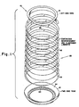
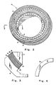
- Figs. 1 through 4 of the drawings illustrate a flexible bearing 10 that is made in accordance with the method of the present invention.
- Bearing 10 includes rigid end rings 12 and 14.
- the end ring 12 is termed a first end ring and the end ring 14 is termed a second end ring.
- the bearing 10 is annular in form with the first end ring 12 comprising the forward end ring and the second end ring 14 comprising the aft end ring.
- Laminate 16 Positioned between the first end ring 12 and the second end ring 14 and bonded thereto is a laminate 16.
- Laminate 16 comprises alternating reinforcement layers 18 and elastomer layers 20 that are wound in a helical arrangement, indicated at 22, between the facing laminate engaging surfaces 24 and 26, respectively, of the first end ring 12 and the second end ring 14.
- the end rings 12 and 14 are made of a suitable material such as steel with the surfaces of each of the end rings adjacent the lamination layers of elastomer and reinforcement conforming to surfaces of concentric spheres.
- Each of the reinforcement layers 18 may comprise pre-impregnated glass cloth 0.050 inches (0.127 cm.) thick with each of the elastomer layers 20 being 0.040 inches (0.102 cm.) thick.
- the elastomer used for layers 20 may comprise calendered natural or synthetic rubber pads having good elastic and holding properties over a wide temperature range.
- a synthetic rubber formulation of polyisoprene may be employed for applications involving ambient temperatures down to 0°F. (-17.77°C.).
- a silicone rubber formulation may be employed for applications involving ambient temperatures down to -65°F. (-53.9°C.).
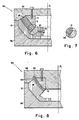
- the mold 28 may be placed between bottom and top plates 30 and 32, respectively, of a hydraulic press 34 which may be of known type, and therefore, will not further be described herein.
- the mold 28 includes a bottom portion 36 having a base 38 and a cylindrical side wall 40 and a circular top portion 42.
- Heat is applied to the laminate 16 simultaneously with the application of pressure thereto by electrically energized Calrod elements 44 and 46 that are operatively associated with the plates 38 and 32, respectively, of the hydraulic press 34. Plates 38 and 32 apply pressure to the end rings 12 and 14 with the laminate 16 therebetween under the force of hydraulic pressure.
- FIG. 6 A modification, designated by reference numeral 50, of the mold 28 of Fig. 5 is illustrated in Fig. 6 wherein a circular ring 52 is provided for containing the alternate layers of reinforcement material 18 and elastomeric material 20 of the laminate 16 at the forward end ring 12 of the flexible bearing 10.
- the circular ring 52 is segmented to enable removal and is held in place by bolting to an inner ring 54.
- the circular top portion, designated 56, of the mold 50 is so configured as to provide a conical inner surface 58 that is operative, when the circular top portion 56 has been pressed into the debulked position of the laminate 16, as shown, to contain the layers of reinforcement and elastomeric material.
- the segmented circular ring 52 and conical surface 58 thus facilitate the application of pressure to the laminate 16 to effect cure and vulcanization.
- An annular recess 64 is provided in the circular top portion, designated 66, adjacent the outer edges of the reinforcement layers 18 and elastomer layers 20. The recess 64 allows the reinforcement layers 18 to be wider than the portions of the end rings 12 and 14 to which they are attached. Thus, as shown in Fig. 8, the outer portion 68 of the reinforcement layers 18 extend beyond the end rings 12 and 14.
- glue may be applied to the reinforcement layers 18 up to the desired outer line indicated at 70 of the bearing connecting the two end rings 12 and 14.
- Elastomer 20 desirably is applied over less than the desired final bearing area, that is the area of each of the surfaces 24 and 26 of the end rings 12 and 14, respectively, to the end that, during debulking, expansion of the elastomer 20 extends to the outer line 70. Any further expansion of the elastomer is inconsequential.
- the alternative method of fabricating the flexible bearing illustrated in Figs. 8 and 9 is especially useful when it is desired to have a thermal barrier on the "outside" of the flexible bearing.
- the reinforcement layers 18 are made using glass fibers in the bearing itself between the end ring surfaces 24 and 26, and carbon fibers are used in the outer portion 64 in the thermal barrier. The bearing is thus protected from heat during the burn of the rocket motor on which the bearing is installed.
- Fig. 10 there is illustrated the pre-impregnated reinforcement material in which a glass/phenolic layer 18 and a carbon/phenolic outer portion or layer 64 are cross-stitched together by stitching indicated by reference numeral 72.
- Fig. 11 shows in longitudinal section a stacking or mandrel tool 74 and an associated laminate removal tool 76 which advantageously may be employed in forming the helical laminate 16, thereby eliminating the need for hand coiling of the laminate 16 on the forward end ring 12 during assembly of the flexible bearing 10.
- the stacking tool 74 includes a conical member 78 having a longitudinal axis 80, a wide end 82 and a narrow end 84.
- Conical member 78 is supported by a vertically positioned shaft 86 to which it is fixedly attached with the axis of the shaft 86 being substantially coincident with the longitudinal axis 80.
- Circumscribing the conical member 78 is a continuous helical ridge 88 upon which the pre-impregnated reinforcement material 18 and elastomeric material 20 may be wound.
- the helical ridge 88 desirably slopes inwardly and upwardly of the conical surface 90 of the conical member 78 toward the narrow end 84 thereof, the angle of such slope with respect to the longitudinal axis 80 of the conical member 78 being about 45°.
- the continous helical coil 22 forming the laminate 16 on the stacking tool 74 When winding the continous helical coil 22 forming the laminate 16 on the stacking tool 74, the latter may be held stationary while the alternate layers of reinforcement material 18 and elastomeric material are hand wound around the helical ridge 88. If desired, suitable provisions may be made, as those skilled in the art will understand, for making the winding operation on the stacking tool 74 automatic, thus eliminating the need for hand winding.
- the removal tool 76 may then be used to lift the laminate from the conical member 78. To this end, the removal tool 76 is moved upwardly (by means not shown) from the full line position to the dotted line position thereof, as shown in Fig. 11, at which an annular surface 92 on an annular shoulder 94 of the removal tool 76 engages the lower surface of the laminate 16. Continued upward movement of the removal tool 76 lifts the laminate 16 completely off the conical member 78.
- the annular surface 92 of the removal tool 76 in transverse section, desirably is correspondingly curved, as shown.
- the removal tool 76 facilitates the lifting of the pre-impregnated laminate 16 from the stacking tool 74 in the proper configuration for debulking.
- methods for simplifying the fabrication of flexible bearings and reducing the production cost thereof comprising, in one embodiment, preparing the pre-impregnated reinforcement layers 18 of the laminate 16 in a continuous helical reinforcement form, placing a first end ring in the bottom of a mold, then coiling the continuous helical reinforcement form with alternating layers of elastomer to form the laminate. A second end ring is then placed in position and the assembly is debulked and cured.
- the pre-impregnated reinforcement layers and elastomer layers are wound into a helical coil on a stacking tool.
- a removal tool associated with the stacking tool facilitates the removal therefrom of the helical coil and the placement thereof on the first end ring in the bottom of the mold.
- the assembly is debulked and cured.
Landscapes
- Engineering & Computer Science (AREA)
- Mechanical Engineering (AREA)
- Chemical & Material Sciences (AREA)
- Composite Materials (AREA)
- General Engineering & Computer Science (AREA)
- Combustion & Propulsion (AREA)
- Moulding By Coating Moulds (AREA)
- Casting Or Compression Moulding Of Plastics Or The Like (AREA)
- Support Of The Bearing (AREA)
Applications Claiming Priority (2)
| Application Number | Priority Date | Filing Date | Title |
|---|---|---|---|
| US183568 | 1988-04-14 | ||
| US07/183,568 US4863367A (en) | 1988-04-14 | 1988-04-14 | Continuous reinforcement method for flexible bearing laminate |
Publications (2)
| Publication Number | Publication Date |
|---|---|
| EP0337648A2 true EP0337648A2 (de) | 1989-10-18 |
| EP0337648A3 EP0337648A3 (de) | 1991-01-09 |
Family
ID=22673369
Family Applications (1)
| Application Number | Title | Priority Date | Filing Date |
|---|---|---|---|
| EP19890303349 Withdrawn EP0337648A3 (de) | 1988-04-14 | 1989-04-05 | Verfahren zum kontinuierlichen Verstärken von flexiblen lamellierten Lagern |
Country Status (3)
| Country | Link |
|---|---|
| US (1) | US4863367A (de) |
| EP (1) | EP0337648A3 (de) |
| JP (1) | JPH01310152A (de) |
Cited By (4)
| Publication number | Priority date | Publication date | Assignee | Title |
|---|---|---|---|---|
| FR2675072A1 (fr) * | 1991-04-15 | 1992-10-16 | Europ Propulsion | Procede de fabrication de butees lamifiees notamment pour articulations de tuyeres de propulseurs. |
| FR2900420A1 (fr) * | 2006-04-26 | 2007-11-02 | Snecma Propulsion Solide Sa | Procede de realisation de strate fibreuse pour la fabrication d'une preforme de piece composite |
| RU2551467C1 (ru) * | 2014-03-11 | 2015-05-27 | Открытое акционерное общество Центральный научно-исследовательский институт специального машиностроения | Каркас поворотного сопла из композиционных материалов, способ его изготовления и выкладочно-прессовочная оснастка для осуществления способа |
| FR3019869A1 (fr) * | 2014-04-09 | 2015-10-16 | Herakles | Butee flexible anti-ecrasement |
Families Citing this family (4)
| Publication number | Priority date | Publication date | Assignee | Title |
|---|---|---|---|---|
| US5352312A (en) * | 1989-05-10 | 1994-10-04 | Thiokol Corporation | Method of insulating a rocket motor |
| RU2173623C1 (ru) * | 2000-01-10 | 2001-09-20 | Открытое акционерное общество Научно-производственное объединение "Искра" | Способ изготовления изделий типа тела вращения с криволинейной поверхностью |
| US10815936B2 (en) | 2016-11-09 | 2020-10-27 | Northrop Grumman Innovation Systems, Inc. | Flexible bearing assemblies, rocket motors including such assemblies, and methods of forming flexible bearings |
| EP4237241A4 (de) * | 2020-10-29 | 2024-10-02 | Chairman, Defence Research&Development Organisation | Verfahren zur herstellung von flexiblen dichtungen und daraus hergestellte flexible dichtungen |
Family Cites Families (11)
| Publication number | Priority date | Publication date | Assignee | Title |
|---|---|---|---|---|
| US1202518A (en) * | 1916-03-14 | 1916-10-24 | Wilfred Thomas Henwood | Unipod for camera-supports. |
| US1665988A (en) * | 1926-06-19 | 1928-04-10 | Smith Leonard Francis | Cleaning rod and extracting device |
| US1827615A (en) * | 1928-05-14 | 1931-10-13 | Rosenberg Heyman | Fastener |
| US3071422A (en) * | 1959-08-10 | 1963-01-01 | William L Hinks | Continuous strip type of static load bearing |
| US3083065A (en) * | 1959-08-10 | 1963-03-26 | William L Hinks | Static load bearing having preformed lateral support features |
| US3193858A (en) * | 1961-03-24 | 1965-07-13 | Gen Am Transport | Methods of producing strong threaded anchorages |
| US3690639A (en) * | 1970-10-05 | 1972-09-12 | Caterpillar Tractor Co | Helically wound laminated bearings and method of manufacture |
| DE3006101A1 (de) * | 1980-02-19 | 1981-08-27 | Metallgesellschaft Ag, 6000 Frankfurt | Werkstuecke mit gepanzerten kanten und/oder flaechen |
| FR2477045A1 (fr) * | 1980-03-03 | 1981-09-04 | Ressorts Ind | Procede et appareillage pour la fabrication de ressorts miniblocs |
| DE3020958C2 (de) * | 1980-06-03 | 1985-09-26 | Hoesch Ag, 4600 Dortmund | Verfahren und Vorrichtung zur Herstellung von Doppelkegelfedern oder dergleichen |
| US4708758A (en) * | 1986-09-25 | 1987-11-24 | Morton Thiokol, Inc. | Method of making a flexible bearing |
-
1988
- 1988-04-14 US US07/183,568 patent/US4863367A/en not_active Expired - Fee Related
-
1989
- 1989-04-03 JP JP1081654A patent/JPH01310152A/ja active Pending
- 1989-04-05 EP EP19890303349 patent/EP0337648A3/de not_active Withdrawn
Cited By (9)
| Publication number | Priority date | Publication date | Assignee | Title |
|---|---|---|---|---|
| FR2675072A1 (fr) * | 1991-04-15 | 1992-10-16 | Europ Propulsion | Procede de fabrication de butees lamifiees notamment pour articulations de tuyeres de propulseurs. |
| GB2254825A (en) * | 1991-04-15 | 1992-10-21 | Europ Propulsion | Manufacturing laminated flexible bearings, in particular for engine nozzle joints |
| US5248361A (en) * | 1991-04-15 | 1993-09-28 | Societe Europeenne De Propulsion | Method of manufacturing laminated flexible bearings, in particular for engine nozzle joints |
| GB2254825B (en) * | 1991-04-15 | 1994-12-14 | Europ Propulsion | A method of manufacturing laminated flexible bearings,in particular for engine nozzle joints |
| FR2900420A1 (fr) * | 2006-04-26 | 2007-11-02 | Snecma Propulsion Solide Sa | Procede de realisation de strate fibreuse pour la fabrication d'une preforme de piece composite |
| WO2007125249A1 (fr) * | 2006-04-26 | 2007-11-08 | Snecma Propulsion Solide | Procede de realisation de strate fibreuse pour la fabrication d'une preforme de piece composite |
| US8034273B2 (en) | 2006-04-26 | 2011-10-11 | Snecma Propulsion Solide | Method of producing a fibrous layer for the manufacture of a preform of a composite part |
| RU2551467C1 (ru) * | 2014-03-11 | 2015-05-27 | Открытое акционерное общество Центральный научно-исследовательский институт специального машиностроения | Каркас поворотного сопла из композиционных материалов, способ его изготовления и выкладочно-прессовочная оснастка для осуществления способа |
| FR3019869A1 (fr) * | 2014-04-09 | 2015-10-16 | Herakles | Butee flexible anti-ecrasement |
Also Published As
| Publication number | Publication date |
|---|---|
| JPH01310152A (ja) | 1989-12-14 |
| US4863367A (en) | 1989-09-05 |
| EP0337648A3 (de) | 1991-01-09 |
Similar Documents
| Publication | Publication Date | Title |
|---|---|---|
| US8034273B2 (en) | Method of producing a fibrous layer for the manufacture of a preform of a composite part | |
| US5223067A (en) | Method of fabricating aircraft fuselage structure | |
| US4927481A (en) | Method of making continuous reinforcement for flexible bearing laminate | |
| US6254812B1 (en) | Method of making a composite part using a compliant forming surface | |
| EP0444627B1 (de) | Struktur und Verfahren zur Herstellung eines Flugzeugrumpfs | |
| US8062452B2 (en) | Method of making a unit comprising a casing and diverging portion | |
| US4683018A (en) | Composite material manufacture by shaping individual sheets followed by consolidating the sheets | |
| JPH0425198B2 (de) | ||
| EP0261902B1 (de) | Verfahren zur Herstellung von vulkanisierten, laminierten, flexiblen Lagern | |
| US5833786A (en) | Titanium radius filler for use in composite interfaces | |
| AU656594B2 (en) | Elliptically ended stiffener for composite structural member, and moulding method for its manufacture | |
| JP4522796B2 (ja) | 繊維強化複合材環状構造体の製造方法、及びその構造体からなる航空機胴体用環状フレーム | |
| US3185605A (en) | Methods of making resin reinforced articles | |
| US4863367A (en) | Continuous reinforcement method for flexible bearing laminate | |
| US5961288A (en) | Process for manufacturing a composite component capable of flexing and twisting | |
| US5252165A (en) | Method of making contoured fiber reinforced body | |
| WO1991014565A1 (en) | Structural component | |
| WO1987001649A1 (en) | Molding apparatus utilizing memory metal alloy springs | |
| US20230366467A1 (en) | Method of producing flexible seals and flexible seals produced therefrom | |
| FIBER et al. | METHOD FOR APPLYING A SKIN LAYER TO AN AIRFOIL STRUCTURE | |
| JPS5892516A (ja) | 成形用金型 | |
| Elliot | Method of Manufacturing an Article From a Fibre Reinforced Composite Material | |
| JPH0160082B2 (de) | ||
| JPH0741682B2 (ja) | Frp製ビームの製造方法 |
Legal Events
| Date | Code | Title | Description |
|---|---|---|---|
| PUAI | Public reference made under article 153(3) epc to a published international application that has entered the european phase |
Free format text: ORIGINAL CODE: 0009012 |
|
| AK | Designated contracting states |
Kind code of ref document: A2 Designated state(s): DE FR GB IT SE |
|
| RAP1 | Party data changed (applicant data changed or rights of an application transferred) |
Owner name: THIOKOL CORPORATION |
|
| PUAL | Search report despatched |
Free format text: ORIGINAL CODE: 0009013 |
|
| AK | Designated contracting states |
Kind code of ref document: A3 Designated state(s): DE FR GB IT SE |
|
| STAA | Information on the status of an ep patent application or granted ep patent |
Free format text: STATUS: THE APPLICATION HAS BEEN WITHDRAWN |
|
| 18W | Application withdrawn |
Withdrawal date: 19910201 |