EP0337671A2 - Système de transmission de signaux pour machines-outils, machines d'inspection et similaires - Google Patents
Système de transmission de signaux pour machines-outils, machines d'inspection et similaires Download PDFInfo
- Publication number
- EP0337671A2 EP0337671A2 EP19890303440 EP89303440A EP0337671A2 EP 0337671 A2 EP0337671 A2 EP 0337671A2 EP 19890303440 EP19890303440 EP 19890303440 EP 89303440 A EP89303440 A EP 89303440A EP 0337671 A2 EP0337671 A2 EP 0337671A2
- Authority
- EP
- European Patent Office
- Prior art keywords
- signal transmission
- signal
- transmission system
- probe
- carrier
- Prior art date
- Legal status (The legal status is an assumption and is not a legal conclusion. Google has not performed a legal analysis and makes no representation as to the accuracy of the status listed.)
- Withdrawn
Links
Images

Classifications
-
- G—PHYSICS
- G01—MEASURING; TESTING
- G01B—MEASURING LENGTH, THICKNESS OR SIMILAR LINEAR DIMENSIONS; MEASURING ANGLES; MEASURING AREAS; MEASURING IRREGULARITIES OF SURFACES OR CONTOURS
- G01B21/00—Measuring arrangements or details thereof, where the measuring technique is not covered by the other groups of this subclass, unspecified or not relevant
- G01B21/02—Measuring arrangements or details thereof, where the measuring technique is not covered by the other groups of this subclass, unspecified or not relevant for measuring length, width, or thickness
- G01B21/04—Measuring arrangements or details thereof, where the measuring technique is not covered by the other groups of this subclass, unspecified or not relevant for measuring length, width, or thickness by measuring coordinates of points
- G01B21/047—Accessories, e.g. for positioning, for tool-setting, for measuring probes
-
- G—PHYSICS
- G01—MEASURING; TESTING
- G01D—MEASURING NOT SPECIALLY ADAPTED FOR A SPECIFIC VARIABLE; ARRANGEMENTS FOR MEASURING TWO OR MORE VARIABLES NOT COVERED IN A SINGLE OTHER SUBCLASS; TARIFF METERING APPARATUS; MEASURING OR TESTING NOT OTHERWISE PROVIDED FOR
- G01D5/00—Mechanical means for transferring the output of a sensing member; Means for converting the output of a sensing member to another variable where the form or nature of the sensing member does not constrain the means for converting; Transducers not specially adapted for a specific variable
- G01D5/26—Mechanical means for transferring the output of a sensing member; Means for converting the output of a sensing member to another variable where the form or nature of the sensing member does not constrain the means for converting; Transducers not specially adapted for a specific variable characterised by optical transfer means, i.e. using infrared, visible, or ultraviolet light
- G01D5/39—Scanning a visible indication of the measured value and reproducing this indication at the remote place, e.g. on the screen of a cathode ray tube
-
- G—PHYSICS
- G08—SIGNALLING
- G08C—TRANSMISSION SYSTEMS FOR MEASURED VALUES, CONTROL OR SIMILAR SIGNALS
- G08C15/00—Arrangements characterised by the use of multiplexing for the transmission of a plurality of signals over a common path
- G08C15/02—Arrangements characterised by the use of multiplexing for the transmission of a plurality of signals over a common path simultaneously, i.e. using frequency division
- G08C15/04—Arrangements characterised by the use of multiplexing for the transmission of a plurality of signals over a common path simultaneously, i.e. using frequency division the signals being modulated on carrier frequencies
-
- G—PHYSICS
- G08—SIGNALLING
- G08C—TRANSMISSION SYSTEMS FOR MEASURED VALUES, CONTROL OR SIMILAR SIGNALS
- G08C23/00—Non-electrical signal transmission systems, e.g. optical systems
- G08C23/04—Non-electrical signal transmission systems, e.g. optical systems using light waves, e.g. infrared
-
- G—PHYSICS
- G01—MEASURING; TESTING
- G01B—MEASURING LENGTH, THICKNESS OR SIMILAR LINEAR DIMENSIONS; MEASURING ANGLES; MEASURING AREAS; MEASURING IRREGULARITIES OF SURFACES OR CONTOURS
- G01B2210/00—Aspects not specifically covered by any group under G01B, e.g. of wheel alignment, caliper-like sensors
- G01B2210/58—Wireless transmission of information between a sensor or probe and a control or evaluation unit
Definitions
- This invention relates to signal transmission systems, e.g. for use on machine tools, coordinate measuring machines, inspection robots, and the like (hereinafter referred to as "machine tools").
- Various probes are known for the inspection of workpieces on such machines. They include trigger probes which provide a trigger signal when they contact or attain a predetermined relationship with a workpiece surface, and measurement probes which provide a digital or analogue output concerning the position of the surface.
- US Patent No. 4,509,266 describes an optical (infra red) transmission system.
- Such systems are also commercially available from Renishaw Metrology Ltd, of Wotton-under-Edge, Gloucestershire, United Kingdom.
- Similar systems can also be used to transmit signals from other sensors, e.g. relating to the presence or position of workpieces on the machine bed or on a conveyor or pallet, or to the status of a device such as a vice, a gripper or a robot. See, for example, US Patent No. 4,545,106.
- Other wireless transmission systems are also known, e.g. using radio waves instead of optical radiation.
- US Patents 4,608,714 and 4,658,509 provide two signals to a single transmitter, and the two signals are modulated onto the infra red beam transmitted by a frequency shift keying (FSK) method.
- the infra red receiver is provided with circuits to demodulate and detect the two signals from the received beam.
- the above-noted commercial systems from Renishaw Metrology Ltd use an asynchronous serial transmission method, in which the infra red beam is switched on to denote a logical '1' and off to denote a logical '0', during serial transmission of a binary word which commences with a start bit, followed by bits representing the desired signal information. This provides for the transmission of greater amounts of information.
- the present invention provides a signal transmission system for a machine tool which has a plurality of sensors for producing a signal in response to a sensed condition, the system comprising: a plurality of signal transmission means, one for each sensor, for transmitting data associated therewith, carrier generating means in each signal transmission means, for generating a carrier signal for transmission by said signal transmission means, the carrier signal of each transmission means having a different frequency, phase modulating means in each signal transmission means, for modulating said data onto said carrier signal by modulating the phase thereof, receiving means for receiving the signals transmitted by the plurality of signal transmission means, and a filter contained in the receiving means, the filter being responsive to the carrier frequency of a said transmission means.
- receivers there may be a plurality of receivers, one for each sensor, each containing a filter responsive to a respective carrier frequency. However, preferably there is one receiver containing a plurality of said filters responsive to the respective different carrier frequencies.
- the data is transmitted by the transmission means in serial binary form.
- the phase modulation may be performed by inverting the phase of the carrier signal to represent a logical "1" or "0" of the binary information.
- the signal transmission means and receiving means transmit and receive the signal optically (e.g. using infra red radiation), but other transmission means can be used such as radio transmission.
- Fig. 1 shows the bed 10 and tool holding spindle 12 of a machine tool.
- the spindle 12 can be moved in X,Y and Z directions relative to the bed 10, in order to perform machining and inspection operations upon a workpiece 14 clamped to the bed 10.
- the spindle 12 can pick up any of a variety of cutting tools (not shown) stored in a tool magazine 16, under the program control of a computer numerical control (not shown).
- the spindle 12 can pick up any of a plurality of battery-operated probes 18A,18B,18C which are also stored in the magazine 16. Three such probes are shown, but there may be only two, or more than three.
- the probes shown in Fig. 1 have workpiece-contacting styli 20, and they may be either touch trigger probes, or measurement or scanning probes which provide outputs proportional to stylus displacement. Alternatively, they may sense the workpiece in a non-contact manner, e.g. optically.
- Each has a circuit 30 (Fig. 2) which generates the touch trigger or other probe output signal, and other signals which are conventional, such as an indication of whether the battery in the probe is in good condition.
- a transmitter unit 46 Fig. 2, including an infra red light emitting diode (LED) 24 on the surface of the probe as shown in Fig. 1.
- more than one such LED can be spaced around the circumference of the probe to provide omni-directional transmission.
- the probe circuit 30 and the transmitter unit 46 are generally conventional, and need not be described further.
- the probe output signals are thus transmitted optically to a receiver module 28 which is interfaced with the numerical control of the machine.
- the transmission circuit (Fig. 2) within each probe contains an encoder 32. This produces a serial binary word which encodes the data from the probe circuit 30.
- the serial binary word is produced by the encoder 32 every time a trigger signal is to be transmitted, and otherwise it is also sent regularly once every 16.4 ms. This provides a "heartbeat" to indicate to the receiver 28 that the probe is functioning.
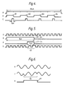
- Each serial binary word is sent in a time window of 64 ⁇ s, and the light emitting diode 24 is entirely off outside these time windows in order to save battery energy. This transmission window is shown at A in Fig. 4.
- Waveform B in Fig. 4 shows four bits of information which are to be encoded into the signal by the encoder.
- a pulse B1 is a start bit; a pulse B2 indicates the probe status; a pulse B3 indicates whether the probe contacts are open or closed; and a pulse B4 indicates the battery condition. It will be appreciated, that with the exception of the start bit B1 which is always high, each of these pulses may be high or low (present or absent), depending on the information to be transmitted.
- the probe status bit B2 is only high if the "probe open or closed" bit B3 has changed state since the last transmission window; this gives a form of error checking and also facilitates immediate recognition of the fact that the probe has just been triggered by contact with the workpiece 14.
- the serial encoder 32 outputs this information in the form shown at C in Fig. 4, on a line 34. It will be seen that each bit of the information signal B corresponds to a 2 ⁇ s pulse C1,C2,C3,C4 (or the absence of such a pulse) in the signal C.
- the information signal shown at Fig. 4B is merely an example of what might be transmitted in respect of a touch trigger probe.
- the serial word may contain more or less 4 bits, depending on the type of sensor and the amount of information which is to be transmitted.
- a measurement probe i.e. one which measures displacement of the stylus 20
- the information may be transmitted over several such binary words, especially if the measurement probe is providing displacement information in three dimensions x,y,z.
- the invention can also be applied to sensors other than probes, for example to sensors for the presence or absence of a workpiece 14 on the bed 10 of the machine tool, or for indicating the operation or status of a vice or gripper or workpiece handling robot or conveyor associated with the machine tool.
- the number of bits in the binary word will be selected to suit the amount of information to be transmitted from each of these different types of sensor.
- the output 34 of the encoder 32 is taken to an exclusive-OR gate 36.
- the other input of the gate 36 is driven by an oscillator 38, which generates a carrier signal.
- the serial encoder 32 has an input 40 from the oscillator 38, so that the pulses of the serial binary word are synchronised with the carrier signal.
- the carrier signal has a different frequency for each of the probes 18A,18B,18C or other sensors of the machine tool, so as to enable the receiver 28 to distinguish signals from different sensors and probes. In particular, the various frequencies of the different probes and sensors are all even multiples or sub-multiples of each other.
- the carrier frequency of one probe may be 500kHz, that of another may be 1MHz, another 2MHz, and so on. Frequencies which are even multiples and sub-multiples of each other are used because it is easier to generate them ( and subsequently to separate them in the receiver module 28). However, this is not essential, as long as the frequencies are different. It will be appreciated that if the pulses C1 to C4 have a width of 2 ⁇ s, then 500kHz is the lowest carrier frequency which can be used.
- the exclusive-OR gate 36 phase modulates the information signal C onto the carrier frequency, by a technique known as phase shift keying (PSK).
- PSK phase shift keying
- Fig. 5 for a 1 MHz carrier signal, shown at D.
- the waveforms B and C from Fig. 4 are reproduced on an expanded scale at E and F in Fig. 5, and the resulting output from the exclusive-OR gate 36 is shown at G.
- the output 44 of the exclusive-OR gate 36 is taken to the transmitter unit 46, and transmitted optically.
- the infra red signal transmitted from the light emitting diode 24 to the receiving photo diode 26 consists of a 64 ⁇ s burst of pulses at 1MHz, phase modulated as just described, repeated every 16.4 ms.
- a receiver unit 50 contains the photo diode 26 which receives the transmitted infra red signals. It feeds the resulting signal to a plurality of band pass filter circuits 52A,52B,52C. Each of these filter circuits is selectively tuned to one of the carrier frequencies of the various probes and sensors, and there is a corresponding filter for each such probe and sensor. Of course, if desired, it would be possible to have a separate receiver circuit 50 and a separate photodiode 26 for each of the filter circuits 52A to 52C.
- Fig. 3 shows the complete circuit for only one of the channels, which receives its signal from the filter 52A, and it will be understood that the other channels are similar.
- the output of the filter 52A is shown in Fig. 6.
- Waveform H shows an idealised sine wave at 1MHZ, corresponding to the carrier signal of waveform D, Fig. 5.
- a likewise idealised version of a portion of the actual signal emanating from the filter 52A is shown at J. As can be seen, it contains a phase-inverted region 54 corresponding to a phase-inverted region 42 in the transmitted signal G.
- the output of the filter 52 is taken to a synchronous demodulator 56, the operation of which is generally conventional.
- Waveform K represents a portion of the output signal appearing on an output line 58.
- a phase-inverted region such as 54 produces a pulse such as shown at K1 in Waveform K.
- the output on the line 58 recreates the serial binary word appearing on the line 34 in the transmitter, as shown at C in Fig. 4.
- This signal is taken to a serial decoder 60, which decodes the binary word and produces outputs 62 corresponding to the original probe information.
- one of the outputs 62 will be a trigger input to the machine interface, which is used to indicate to the machine that the probe has just contacted a workpiece 14.
- the machine numerical control programme will take a reading of the instantaneous coordinates of the machine spindle 12, and will also halt movement of the spindle so as to prevent the probe being driven further into the workpiece 14 (which could cause damage).
- the outputs of the serial decoder 60 will be as appropriate for the sensor concerned.
- the transmitter described uses very little power, which leads to long battery life. This is important since it is desirable with such probes that the batteries should require changing as infrequently as possible. Furthermore, the transmitter can be an all-digital system, which further saves power and is easy to implement.
Landscapes
- Physics & Mathematics (AREA)
- General Physics & Mathematics (AREA)
- Arrangements For Transmission Of Measured Signals (AREA)
- Optical Communication System (AREA)
- Digital Transmission Methods That Use Modulated Carrier Waves (AREA)
Applications Claiming Priority (2)
| Application Number | Priority Date | Filing Date | Title |
|---|---|---|---|
| GB8808613 | 1988-04-12 | ||
| GB888808613A GB8808613D0 (en) | 1988-04-12 | 1988-04-12 | Signal transmission system for machine tools inspection machines &c |
Publications (2)
| Publication Number | Publication Date |
|---|---|
| EP0337671A2 true EP0337671A2 (fr) | 1989-10-18 |
| EP0337671A3 EP0337671A3 (fr) | 1990-03-28 |
Family
ID=10635051
Family Applications (1)
| Application Number | Title | Priority Date | Filing Date |
|---|---|---|---|
| EP89303440A Withdrawn EP0337671A3 (fr) | 1988-04-12 | 1989-04-07 | Système de transmission de signaux pour machines-outils, machines d'inspection et similaires |
Country Status (4)
| Country | Link |
|---|---|
| US (1) | US5056235A (fr) |
| EP (1) | EP0337671A3 (fr) |
| JP (1) | JPH0216824A (fr) |
| GB (1) | GB8808613D0 (fr) |
Cited By (7)
| Publication number | Priority date | Publication date | Assignee | Title |
|---|---|---|---|---|
| EP0506318A1 (fr) * | 1991-03-29 | 1992-09-30 | Renishaw Metrology Limited | Dispositif de transmission de signaux pour sonde à déclenchement |
| WO1995028615A1 (fr) * | 1994-04-19 | 1995-10-26 | Marposs Societa' Per Azioni | Systeme de detection de mesures de longueur et procede destine a tester le bon fonctionnement du systeme |
| US5564872A (en) * | 1994-03-21 | 1996-10-15 | Veil; Wilfried | Implement for machine tools and process for generating electric power in one such implement |
| FR2762110A1 (fr) * | 1997-04-14 | 1998-10-16 | Renishaw Plc | Systeme formant capteur programmable |
| WO1999047884A1 (fr) * | 1998-03-13 | 1999-09-23 | Marposs Societa' Per Azioni | Tete, systeme et procede de verification de la dimension lineaire d'une piece mecanique |
| WO1999047883A3 (fr) * | 1998-03-13 | 2000-08-10 | Marposs Spa | Tete, appareil et procede pour le controle lineaire des dimensions de pieces mecaniques |
| US6839563B1 (en) | 1998-02-11 | 2005-01-04 | Renishaw, Plc | Signal transmission circuit for probe |
Families Citing this family (28)
| Publication number | Priority date | Publication date | Assignee | Title |
|---|---|---|---|---|
| CA2060485C (fr) * | 1991-02-05 | 2003-01-07 | Ruggero Cadossi | Dispositif de detection et de signalisation de contact |
| US5327657A (en) * | 1991-07-11 | 1994-07-12 | Renishaw Metrology Ltd. | Touch probe |
| WO1993009398A1 (fr) * | 1991-11-09 | 1993-05-13 | Renishaw Metrology Limited | Capteur tactile |
| DE19630823C1 (de) * | 1996-07-31 | 1997-12-11 | Zeiss Carl Fa | Koordinatenmeßgerät mit Kollisionsschutz |
| US5854994A (en) * | 1996-08-23 | 1998-12-29 | Csi Technology, Inc. | Vibration monitor and transmission system |
| US6301514B1 (en) | 1996-08-23 | 2001-10-09 | Csi Technology, Inc. | Method and apparatus for configuring and synchronizing a wireless machine monitoring and communication system |
| DE19653247A1 (de) * | 1996-10-21 | 1998-04-30 | Koenig & Bauer Albert Ag | Bogenbearbeitungsmaschine |
| GB9826093D0 (en) * | 1998-11-28 | 1999-01-20 | Limited | Locating arm for a probe on a coordinate positioning machine |
| GB2349949B (en) * | 1999-05-14 | 2003-03-05 | Taylor Hobson Ltd | Metrological instrument |
| US6475301B1 (en) | 1999-07-06 | 2002-11-05 | Visteon Global Technologies, Inc. | Conversion coatings on aluminum from KF solutions |
| DE10132554B4 (de) * | 2001-07-04 | 2011-07-07 | Dr. Johannes Heidenhain GmbH, 83301 | Verfahren zum Betreiben eines Tastsystems sowie Tastsystem zur Ausführung des Verfahrens |
| US6772527B1 (en) * | 2003-04-09 | 2004-08-10 | Renishaw Plc | Modular measurement device |
| GB0518078D0 (en) * | 2005-09-06 | 2005-10-12 | Renishaw Plc | Signal transmission system |
| EP1923805A1 (fr) * | 2006-11-20 | 2008-05-21 | Baumer IVO GmbH & Co. KG | Dispositif de mesure de positions avec la transmission de données sans fil |
| DE102006054978A1 (de) * | 2006-11-22 | 2008-05-29 | Dr. Johannes Heidenhain Gmbh | Tastsystem |
| EP2028439A1 (fr) * | 2007-07-26 | 2009-02-25 | Renishaw plc | Appareil de mesure pouvant être désactivé |
| DE102007054838A1 (de) * | 2007-11-16 | 2009-05-20 | Dr. Johannes Heidenhain Gmbh | Tastsystem und Verfahren zum Betrieb eines Tastsystems |
| JP5262630B2 (ja) * | 2008-12-01 | 2013-08-14 | 富士通株式会社 | セルフテスト回路を有するクロック生成回路 |
| JP5451180B2 (ja) * | 2009-05-22 | 2014-03-26 | 株式会社ミツトヨ | 真円度測定機 |
| DE102010040195A1 (de) * | 2009-10-28 | 2011-05-05 | Dr. Johannes Heidenhain Gmbh | Tastsystem und Verfahren zum Betrieb eines Tastsystems |
| US9333607B2 (en) * | 2011-05-19 | 2016-05-10 | Makino Milling Machine Co., Ltd. | Machine tool having workpiece measurement function |
| GB201222274D0 (en) * | 2012-12-11 | 2013-01-23 | Renishaw Plc | Radio interface |
| DE102013016715A1 (de) * | 2013-10-09 | 2015-04-09 | M & H Inprocess Messtechnik Gmbh | Messvorrichtung für eine Werkzeugmaschine |
| JP7008044B2 (ja) * | 2016-07-01 | 2022-01-25 | 株式会社ミツトヨ | 座標測定機のための取り外し可能なプローブに電力を供給するための電力伝達構成体 |
| EP3575738A1 (fr) * | 2018-06-01 | 2019-12-04 | Siemens Aktiengesellschaft | Mesure simultanée pour machines-outils multibroche |
| DE102020100208B4 (de) * | 2020-01-08 | 2022-02-24 | Rovema Gmbh | Verfahren zur Verstellung mehrerer Maschinenelemente an einer Verpackungsmaschine |
| US11524410B2 (en) * | 2020-06-12 | 2022-12-13 | Hexagon Metrology, Inc. | Robotic alignment method for workpiece measuring systems |
| GB202103105D0 (en) * | 2021-03-05 | 2021-04-21 | Renishaw Plc | Measurement probe |
Family Cites Families (12)
| Publication number | Priority date | Publication date | Assignee | Title |
|---|---|---|---|---|
| US3032745A (en) * | 1959-04-07 | 1962-05-01 | Electronic Associates | Data transmission system |
| US3290667A (en) * | 1963-09-30 | 1966-12-06 | Paul T Stine | Automatic frequency deviation control system for subcarrier oscillator |
| US3582921A (en) * | 1968-08-06 | 1971-06-01 | Charles R Krieger | Temperature transducer and telemetry system |
| GB1333951A (en) * | 1971-03-08 | 1973-10-17 | Standard Telephones Cables Ltd | Electrical supervisory system |
| JPS5391612A (en) * | 1977-01-24 | 1978-08-11 | Nec Corp | Receiver for multiple frequency signal |
| US4545106A (en) * | 1981-04-30 | 1985-10-08 | Gte Valeron Corporation | Machine system using infrared telemetering |
| US4509266A (en) * | 1982-06-14 | 1985-04-09 | Gte Valeron Corporation | Touch probe |
| US4608714A (en) * | 1982-09-03 | 1986-08-26 | Gte Valeron Corporation | Low battery detector for a machine system using infrared telemetry |
| EP0165941A1 (fr) * | 1983-12-22 | 1986-01-02 | School of Science Griffith University | Systeme de transmission a modulation de phase et manipulation de dephasage |
| US4693110A (en) * | 1985-06-06 | 1987-09-15 | Gte Valeron Corporation | Method and apparatus for testing the operability of a probe |
| US4658509A (en) * | 1985-09-12 | 1987-04-21 | Gte Valeron Corporation | Probe having low battery detection/transmission feature |
| GB2203837B (en) * | 1987-04-06 | 1991-02-20 | Mitutoyo Corp | Apparatus and method for spatial coordinate measurement |
-
1988
- 1988-04-12 GB GB888808613A patent/GB8808613D0/en active Pending
-
1989
- 1989-04-07 EP EP89303440A patent/EP0337671A3/fr not_active Withdrawn
- 1989-04-07 US US07/334,537 patent/US5056235A/en not_active Expired - Fee Related
- 1989-04-12 JP JP1090896A patent/JPH0216824A/ja active Pending
Cited By (18)
| Publication number | Priority date | Publication date | Assignee | Title |
|---|---|---|---|---|
| EP0506318A1 (fr) * | 1991-03-29 | 1992-09-30 | Renishaw Metrology Limited | Dispositif de transmission de signaux pour sonde à déclenchement |
| FR2674659A1 (fr) * | 1991-03-29 | 1992-10-02 | Renishan Metrology Ltd | Dispositif de transmission de signaux pour sonde a declenchement. |
| US5279042A (en) * | 1991-03-29 | 1994-01-18 | Renishaw Metrology Limited | Signal transmission system for trigger probe |
| EP0652413A3 (fr) * | 1991-03-29 | 1996-06-12 | Renishaw Metrology Ltd | Dispositif de transmission de signaux pour sonde à déclenchement. |
| US5564872A (en) * | 1994-03-21 | 1996-10-15 | Veil; Wilfried | Implement for machine tools and process for generating electric power in one such implement |
| WO1995028615A1 (fr) * | 1994-04-19 | 1995-10-26 | Marposs Societa' Per Azioni | Systeme de detection de mesures de longueur et procede destine a tester le bon fonctionnement du systeme |
| US5778550A (en) * | 1994-04-19 | 1998-07-14 | Marposs Societa' Per Azioni | System for detecting linear dimensions and method for testing the system operability |
| EP0872787A1 (fr) * | 1997-04-14 | 1998-10-21 | Renishaw plc | Système de capteur programmable |
| FR2762110A1 (fr) * | 1997-04-14 | 1998-10-16 | Renishaw Plc | Systeme formant capteur programmable |
| US6301796B1 (en) | 1997-04-14 | 2001-10-16 | Renishaw Plc | Programmable probe system |
| US6839563B1 (en) | 1998-02-11 | 2005-01-04 | Renishaw, Plc | Signal transmission circuit for probe |
| WO1999047884A1 (fr) * | 1998-03-13 | 1999-09-23 | Marposs Societa' Per Azioni | Tete, systeme et procede de verification de la dimension lineaire d'une piece mecanique |
| WO1999047883A3 (fr) * | 1998-03-13 | 2000-08-10 | Marposs Spa | Tete, appareil et procede pour le controle lineaire des dimensions de pieces mecaniques |
| US6487896B1 (en) | 1998-03-13 | 2002-12-03 | Marposs Societa' Per Azioni | Head, system and method for the linear dimension checking of a mechanical piece |
| US6546642B1 (en) | 1998-03-13 | 2003-04-15 | Marposs Societa' Per Azioni | Head, apparatus and method for the linear dimension checking of mechanical pieces |
| US6920698B2 (en) | 1998-03-13 | 2005-07-26 | Marposs, S.P.A. | Head and apparatus for the linear dimension checking of mechanical pieces |
| US7076882B2 (en) | 1998-03-13 | 2006-07-18 | Marposs Societa' Per Azioni | Head and apparatus for the linear dimension checking of mechanical pieces |
| US7266900B2 (en) | 1998-03-13 | 2007-09-11 | Marposs Societa' Per Azioni | Apparatus for the linear dimension checking of mechanical pieces |
Also Published As
| Publication number | Publication date |
|---|---|
| US5056235A (en) | 1991-10-15 |
| JPH0216824A (ja) | 1990-01-19 |
| GB8808613D0 (en) | 1988-05-11 |
| EP0337671A3 (fr) | 1990-03-28 |
Similar Documents
| Publication | Publication Date | Title |
|---|---|---|
| US5056235A (en) | Signal transmission system for machine tools, inspection machines, and the like | |
| EP0337669B1 (fr) | Système de transmission de signaux pour machines-outils, machines d'inspection et similaires | |
| EP1576560B1 (fr) | Systeme de transmission de signaux destine a un dispositif de mesure | |
| US4545106A (en) | Machine system using infrared telemetering | |
| EP0826201B1 (fr) | Dispositif et procede de transmission sans fil de signaux entre une tete de mesure et un recepteur situe a distance | |
| US20080110039A1 (en) | Probe system and method for operating a probe system | |
| US4608714A (en) | Low battery detector for a machine system using infrared telemetry | |
| EP1649330B1 (fr) | Systeme et procede pour la verification des dimensions de pieces mecaniques | |
| EP0830660B1 (fr) | Dispositif et procede de transmission a distance de signaux pour sondes de detection | |
| EP0337670A2 (fr) | Système de transmission pour machines, outils, machines d'inspection et similaires | |
| WO1985000651A1 (fr) | Appareil de detection d'une position | |
| US7716847B2 (en) | Probe system and method for operating a probe system | |
| KR102628296B1 (ko) | 산업 장치의 2개의 전자 디바이스 간의 통신을 위한 무선 디지털 통신 방법 및 시스템 | |
| CN104759927A (zh) | 数控机床刀库刀具检测系统 | |
| JPS6141699B2 (fr) | ||
| JPS5830556B2 (ja) | 波動送受信装置 | |
| JPS6211984B2 (fr) | ||
| JPS60121848A (ja) | 装置間通信方式 | |
| JPH04282701A (ja) | データ伝送方法 |
Legal Events
| Date | Code | Title | Description |
|---|---|---|---|
| PUAI | Public reference made under article 153(3) epc to a published international application that has entered the european phase |
Free format text: ORIGINAL CODE: 0009012 |
|
| 17P | Request for examination filed |
Effective date: 19890417 |
|
| AK | Designated contracting states |
Kind code of ref document: A2 Designated state(s): CH DE FR GB IT LI SE |
|
| PUAL | Search report despatched |
Free format text: ORIGINAL CODE: 0009013 |
|
| AK | Designated contracting states |
Kind code of ref document: A3 Designated state(s): CH DE FR GB IT LI SE |
|
| RAP3 | Party data changed (applicant data changed or rights of an application transferred) |
Owner name: RENISHAW PLC |
|
| STAA | Information on the status of an ep patent application or granted ep patent |
Free format text: STATUS: THE APPLICATION HAS BEEN WITHDRAWN |
|
| 18W | Application withdrawn |
Withdrawal date: 19920221 |
|
| R18W | Application withdrawn (corrected) |
Effective date: 19920218 |