EP0337796A2 - Vorrichtung zur Messung der Kennzeichen der optischen Frequenzmodulation - Google Patents
Vorrichtung zur Messung der Kennzeichen der optischen Frequenzmodulation Download PDFInfo
- Publication number
- EP0337796A2 EP0337796A2 EP89303703A EP89303703A EP0337796A2 EP 0337796 A2 EP0337796 A2 EP 0337796A2 EP 89303703 A EP89303703 A EP 89303703A EP 89303703 A EP89303703 A EP 89303703A EP 0337796 A2 EP0337796 A2 EP 0337796A2
- Authority
- EP
- European Patent Office
- Prior art keywords
- frequency
- optical
- signals
- mach
- difference
- Prior art date
- Legal status (The legal status is an assumption and is not a legal conclusion. Google has not performed a legal analysis and makes no representation as to the accuracy of the status listed.)
- Granted
Links
Images


Classifications
-
- H—ELECTRICITY
- H04—ELECTRIC COMMUNICATION TECHNIQUE
- H04B—TRANSMISSION
- H04B10/00—Transmission systems employing electromagnetic waves other than radio-waves, e.g. infrared, visible or ultraviolet light, or employing corpuscular radiation, e.g. quantum communication
- H04B10/60—Receivers
- H04B10/66—Non-coherent receivers, e.g. using direct detection
- H04B10/69—Electrical arrangements in the receiver
-
- G—PHYSICS
- G01—MEASURING; TESTING
- G01J—MEASUREMENT OF INTENSITY, VELOCITY, SPECTRAL CONTENT, POLARISATION, PHASE OR PULSE CHARACTERISTICS OF INFRARED, VISIBLE OR ULTRAVIOLET LIGHT; COLORIMETRY; RADIATION PYROMETRY
- G01J9/00—Measuring optical phase difference; Determining degree of coherence; Measuring optical wavelength
- G01J9/02—Measuring optical phase difference; Determining degree of coherence; Measuring optical wavelength by interferometric methods
-
- G—PHYSICS
- G02—OPTICS
- G02F—OPTICAL DEVICES OR ARRANGEMENTS FOR THE CONTROL OF LIGHT BY MODIFICATION OF THE OPTICAL PROPERTIES OF THE MEDIA OF THE ELEMENTS INVOLVED THEREIN; NON-LINEAR OPTICS; FREQUENCY-CHANGING OF LIGHT; OPTICAL LOGIC ELEMENTS; OPTICAL ANALOGUE/DIGITAL CONVERTERS
- G02F2/00—Demodulating light; Transferring the modulation of modulated light; Frequency-changing of light
-
- H—ELECTRICITY
- H04—ELECTRIC COMMUNICATION TECHNIQUE
- H04B—TRANSMISSION
- H04B10/00—Transmission systems employing electromagnetic waves other than radio-waves, e.g. infrared, visible or ultraviolet light, or employing corpuscular radiation, e.g. quantum communication
- H04B10/60—Receivers
- H04B10/66—Non-coherent receivers, e.g. using direct detection
- H04B10/67—Optical arrangements in the receiver
- H04B10/676—Optical arrangements in the receiver for all-optical demodulation of the input optical signal
-
- G—PHYSICS
- G01—MEASURING; TESTING
- G01J—MEASUREMENT OF INTENSITY, VELOCITY, SPECTRAL CONTENT, POLARISATION, PHASE OR PULSE CHARACTERISTICS OF INFRARED, VISIBLE OR ULTRAVIOLET LIGHT; COLORIMETRY; RADIATION PYROMETRY
- G01J9/00—Measuring optical phase difference; Determining degree of coherence; Measuring optical wavelength
- G01J9/02—Measuring optical phase difference; Determining degree of coherence; Measuring optical wavelength by interferometric methods
- G01J2009/0226—Fibres
Definitions
- This invention is applicable to measurement of optical communication equipments. More particularly, this invention is applicable to measurement of modulation characteristics of optical signals which have been modulated in frequency. This invention device is most suitable to measure modulation characteristics of optical signals for coherent light communications which have been emitted from a laser diode and modulated in frequency.
- Frequency modulation system has been known as an effective method for coherent optical communications.
- Simple transmitters can be structured by using frequency-modulated signals obtained by giving signals for modulation directly to the laser diode.
- Frequency-modulated signals obtained by directly modulating laser diode contain an amplitude modulation component as well as a frequency modulation component.
- the measurement of frequency modulation component requires a measurement method which is less prone to the influence of amplitude modulation component.
- the frequency modulation response of laser diode is influenced mainly by the frequency changes caused by thermal effect in low modulation frequency region, and mainly by the effect of carrier in high modulation frequency region.
- the direction of frequency changes of these two effects are opposite to each other, and the frequency modulation response to injection current to laser diode is not uniform.
- a circuit which can faithfully convert changes in frequency of optical signals into changes in voltage.
- a Fabry-Perot etalon has conventionally been utilized for measurements of this type.
- a Fabry-Perot etalon is a device comprising two parallel plates between which an object light is entered at an incident angle. An interference pattern is formed when the light is repeatedly reflected between the two parallel plates. If the distance d between the two plates and the angle ⁇ are fixed, the interference pattern is determinable by the frequency of the incident light. Etalons which measure changes in frequency (or wave length) of light by the interference pattern are widely known.
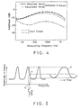
- FIG. 5 is a characteristic graph which shows the relation between the input light frequency and the output light amplitude of such an etalon.
- the optical frequency is plotted on the horizontal axis while the optical power of the output light is plotted on the vertical axis.
- the graph shows changes in intensity of the light which is outputted from the etalon as against the frequency changes. If a point a at a large gradient of the characteristic curve is selected in the graph and an incident light which has been modulated in the frequency with its center placed at the frequency fa of the point a is given to an etalon, the optical signals in terms of changes in optical power are obtained as shown by the curve b in FIG. 5.
- the frequency modulation response can be measured by converting to voltage signals with a photo-detector the optical signals which have already been converted to optical power change.
- the above mentioned instrumentation method is problematic in the following aspects: (1) As the steep changes in frequency are limited, it cannot measure a wider frequency range; (2) as it uses multiple reflection, propagation time difference between reflected waves and traveling waves prevents to measure frequency modulation response in a high frequency range; and (3) distortion occurs when the frequency deviation of input light is large.
- the first problem there has been known a technique of varying measurable frequency range by moving one of the reflective mirrors of the etalon or by changing the incident angle of the light, but the method needs an extremely precise and complicated mechanism.
- Mach-Zehnder interferometers Another method which conceivably causes interference patterns is the use of Mach-Zehnder interferometers.
- Mach-Zehnder interferometer has excellent response characteristic even in the high frequency range and shows gentle changes in optical power over the wider range of frequency of the input light, the light signals which have passed through Mach-Zehnder interferometer are directly influenced by the amplitude changes of the input light, and therefore it has been regarded heretofore not quite suitable as an instrumentation device for separately measuring the frequency modulation component and the amplitude modulation component.
- This invention was conceived in order to solve such problems encountered in the prior art and aims to provide an instrumentation device which can measure frequency modulation component over a wide frequency range and which is extremely simple in mechanism.
- This invention device is characterized in that two photo-detectors are provided to the two optical output ports of a Mach-Zehnder interferometer, and an electric circuit means is provided to output signals showing the difference of output signals between the two photo-detectors.
- This invention device is further characterized in that a means which controls the difference of the two optical path lengths of the interferometer is provided, and the means is controlled with input signals from a controller depending on the difference in said output electric signals. More preferably, it is controlled with input signals from the controller in a manner to make the time average of the difference zero.
- the difference in optical path lengths can be controlled by controlling the temperature of the paths.
- the Mach-Zehnder interferometer herein comprises two input ports 11, 12, a first coupler 15 which reunites with interference the optical signals from two waveguides which respectively guide the input lights from these input ports, two waveguides 13, 14 which guide the two optical signals respectively after they have been passed through the coupler and interfered with each other, a second coupler 16 which couples with interference the optical signals from said two waveguides, and two output ports 17, 18 which output the two optical signals which have been passed the second coupler and interfered with each other, a propagation time difference ( ⁇ ) being given in the optical path lengths of the two waveguides between the first and the second couplers.
- ⁇ propagation time difference
- optical signals when an optical signal is inputted at one 12 of the two input ports 11, 12, the optical signal is divided into two waveguides 13, 14 from the first coupler 15, propagate respectively with different propagation time, and when interfered with each other at the second coupler 16, so-called optical signals having the optical power which cyclicly changes depending on the frequency of the input light signal are obtained at the two output ports 17, 18.
- optical power signals with anti- phases by the changes in frequency of input light.
- the effect of amplitude changes of input light appears with the same phase between the two optical output ports of the interferometer. Therefore, by subtracting the signals appearing at the two optical output ports, the effect of the amplitude modulation of input light can be cancelled, and the changes in optical power as against the frequency changes becomes twice as much.
- This method comprises the steps of receiving the optical outputs from the two output ports and obtaining the difference therebetween to cancel the amplitude change components to a certain extent. This will be explained by the equations below.
- the signals at the input port 12 are expressed as below.
- S (t) A cos ⁇ t + ⁇ (t) ⁇ (1) wherein A denotes the electric field of the light, ⁇ the angular frequency thereof and ⁇ (t) the frequency modulation signals.
- S3, S4 at the two output ports 17, 18 are expressed as below;
- S3 (t) -A x cos[ ⁇ /2 + ⁇ (t) - ⁇ (t - ⁇ ) ⁇ /2] x sin [ ⁇ t - ⁇ /2 + ⁇ (t) + ⁇ (t - ⁇ ) ⁇ /2] (4)
- S4 (t) -A x sin[ ⁇ /2 + ⁇ (
- the frequency modulation signal ⁇ (t) can be expressed by the equation below. wherein ⁇ denotes modulation index, ⁇ m modulation angular frequency, and ⁇ an arbitrary phase. If they are substituted in the equation (10), the following relation holds. Therefore, the relation below will hold. In other words, the optical propagation time difference ⁇ must satisfy the relation expressed below in order to detect the signals faithfully.
- This invention provides a device which can measure the frequency modulation component of signals without influence from the amplitude modulation component by using the difference between the signals appearing at the two output ports of Mach-Zehnder interferometer as the measurement output.
- FIG. 1 is a structural view of an embodiment of this invention.
- the device includes a Mach-Zehnder interferometer to which the light to be measured is inputted after it has been frequency-modulated, and photo-detectors 2 and 3 which convert the optical powers of the output light from the Mach-Zehnder interferometer 1 into electric signals.
- the number of the photo-detectors provided is two which are respectively mounted at the two optical output ports of the interferometer. The arrangement is a feature of this invention.
- the device is so structured to connect the two detectors 2 and 3 in serial to and the voltage of anode of the photo-detector 2 and the voltage of cathode of the photo-detector 3, and the difference in the output signals in transmitted to an output terminal 5 via an amplifier 4.
- a heater 6 is provided in the Mach-Zehnder interferometer in order to control the difference between the two optical path lengths, and a transistor 7 is provided to control the electric current of the heater 6.
- the transistor 7 is connected on the control electrode thereof with a controller 8 which gives controlling input in accordance with the difference between the two output signals.
- the Mach-Zehnder interferometer 1 comprises optical waveguides 13 and 14 formed on a silicon substrate.
- the reference numerals 11 and 12 denote optical input ports, 15 and 16 directional couplers, and 17 and 18 two optical output ports.
- the two optical waveguides 13 and 14 are designed to have lengths which differ in optical propagation time by ⁇ from each other.
- FIG. 2 is a schematic view of a Mach-Zehnder interferometer.
- the output lights at the two output ports 17 and 18 interfere with each other. The interference changes by the frequency. Therefore, the relation between amplitude and frequency as shown in FIG. 3 graph is obtained between the input light frequency at the port 12 and the optical power at the two output ports 17 and 18.
- the solid line shows the characteristics of the output light from the port 17 while the broken line shows the characteristics of the output light from the port 18.
- the optical powers at the output ports 17 and 18 change correspondingly to the changes in frequency of the input light as shown in FIG. 3(1).
- the changes in optical power of the two lights are directed in opposite directions to each other at the ports 17 and 18, and if the signals detected at the two ports 17 and 18 are subtracted from each other, then the amplitude will become twice that shown in FIG. 3(4).
- the input light is the frequency modulation signal obtained by directly modulating a laser diode, it includes not only frequency modulation component but also amplitude modulation component.
- the effect of the amplitude changes included in the input light after the outputs at the ports 17 and 18 as it is as shown in FIG. 3(2).
- the solid line represents the small amplitude modulation component and the dot-and-dash line expresses the large amplitude modulation component.
- the amplitude modulation component has the same phase as that of the amplitude component at the port 17 which has been converted from frequency component, the optical amplitude at the port 17 becomes larger as shown in FIG. 3(3) while that at the port 18 becomes smaller.
- the effect of the two amplitude changes is cancelled by subtracting one of the signals detected at the two ports 17 and 18 from the other as shown in FIG. 3(4).
- This embodiment is so structured that optical paths will change effectively in accordance with the temperature controlled by the heater 6 to thereby vary said time ⁇ .
- the signal representing the difference between the two photo-detectors 2 and 3 will be given at the input of the controller 8.
- the controller 8 comprises a comparator which compares the input signal with zero voltage and a low-pass filter which passes the output from the comparator so that the signals representing said difference becomes zero voltage in average when it is given in the input.
- FIG. 4 shows an example of measurement result obtained by means of this embodiment device.
- the graph shows the result of the measurement of the levels of detected outputs or signals which represents said difference.
- the light has been modulated in frequency by direct modulation method of a laser diode, and the frequency plotted on the horizontal axis represents the modulated frequency.
- the result of measurement of one output light at an output port of the same Mach-Zehnder interferometer is shown in the graph as against the measured lights at two output ports.
- the values represented with filled circles are the calculated frequency modulation responses which are expected to appear.
- the one represented with a-dot-and-dash line has the frequency modulation component and amplitude modulation component in opposite phases to each other.
- the measured amplitude is small.
- the one expressed with broken line has the two components in the same phase. The result indicates that when only one of the outputs from the Mach-Zehnder interferometer is measured, due to the effect of the amplitude modulation component included in the object signal, the frequency modulation component is not properly measured. But when the difference beween the output lights from the two output ports is measured, the frequency modulation component alone can be separated and measured.
- this invention is not limited to the arrangement. This invention may be realized by using other types of Mach-Zehnder interferometer which form an optical path in a space to have the similar effect.
- the effective length of an optical path may be controlled by various means other than the heating method used in the above description so far as it can control the length to embody this invention.
Landscapes
- Physics & Mathematics (AREA)
- Electromagnetism (AREA)
- Engineering & Computer Science (AREA)
- Computer Networks & Wireless Communication (AREA)
- Signal Processing (AREA)
- Spectroscopy & Molecular Physics (AREA)
- General Physics & Mathematics (AREA)
- Nonlinear Science (AREA)
- Optics & Photonics (AREA)
- Instruments For Measurement Of Length By Optical Means (AREA)
- Optical Communication System (AREA)
- Spectrometry And Color Measurement (AREA)
Applications Claiming Priority (2)
| Application Number | Priority Date | Filing Date | Title |
|---|---|---|---|
| JP92783/88 | 1988-04-14 | ||
| JP9278388 | 1988-04-14 |
Publications (3)
| Publication Number | Publication Date |
|---|---|
| EP0337796A2 true EP0337796A2 (de) | 1989-10-18 |
| EP0337796A3 EP0337796A3 (de) | 1991-04-10 |
| EP0337796B1 EP0337796B1 (de) | 1994-07-06 |
Family
ID=14064018
Family Applications (1)
| Application Number | Title | Priority Date | Filing Date |
|---|---|---|---|
| EP89303703A Expired - Lifetime EP0337796B1 (de) | 1988-04-14 | 1989-04-14 | Vorrichtung zur Messung der Kennzeichen der optischen Frequenzmodulation |
Country Status (3)
| Country | Link |
|---|---|
| US (1) | US4979825A (de) |
| EP (1) | EP0337796B1 (de) |
| DE (1) | DE68916576T2 (de) |
Cited By (5)
| Publication number | Priority date | Publication date | Assignee | Title |
|---|---|---|---|---|
| EP0473873A1 (de) * | 1990-08-30 | 1992-03-11 | Landis & Gyr Business Support AG | Vorrichtung zum Empfang wellenlängen-modulierter Lichtsignale |
| DE19755402A1 (de) * | 1997-12-12 | 1999-08-05 | Litef Gmbh | Wellenlängenmeßeinrichtung mit mittelwertfrei angesteuertem Mach-Zehnder-Interferometer |
| GB2385144A (en) * | 2002-01-23 | 2003-08-13 | Marconi Optical Components Ltd | Optical signal demodulators |
| US6891149B1 (en) | 1998-09-22 | 2005-05-10 | Qinetiq Limited | Optical phase detector |
| EP1672311A1 (de) * | 2004-12-20 | 2006-06-21 | Electronics And Telecommunications Research Institute | Vorrichtung und Verfahren zur Steuerung eines optischen Interferometers |
Families Citing this family (2)
| Publication number | Priority date | Publication date | Assignee | Title |
|---|---|---|---|---|
| WO2013146406A1 (ja) * | 2012-03-30 | 2013-10-03 | 日本電気株式会社 | 導波路結合msm型フォトダイオード |
| US20250314830A1 (en) * | 2024-04-08 | 2025-10-09 | Mellanox Technologies, Ltd. | Hybrid ring-interferometer tuning systems for efficient ring-assisted interferometer control |
Family Cites Families (2)
| Publication number | Priority date | Publication date | Assignee | Title |
|---|---|---|---|---|
| US3508060A (en) * | 1965-01-14 | 1970-04-21 | Westinghouse Electric Corp | Light frequency receiver |
| SE447601B (sv) * | 1985-04-04 | 1986-11-24 | Ericsson Telefon Ab L M | Fiberoptisk interferometer |
-
1989
- 1989-04-13 US US07/337,741 patent/US4979825A/en not_active Expired - Lifetime
- 1989-04-14 DE DE68916576T patent/DE68916576T2/de not_active Expired - Lifetime
- 1989-04-14 EP EP89303703A patent/EP0337796B1/de not_active Expired - Lifetime
Cited By (8)
| Publication number | Priority date | Publication date | Assignee | Title |
|---|---|---|---|---|
| EP0473873A1 (de) * | 1990-08-30 | 1992-03-11 | Landis & Gyr Business Support AG | Vorrichtung zum Empfang wellenlängen-modulierter Lichtsignale |
| DE19755402A1 (de) * | 1997-12-12 | 1999-08-05 | Litef Gmbh | Wellenlängenmeßeinrichtung mit mittelwertfrei angesteuertem Mach-Zehnder-Interferometer |
| DE19755402C2 (de) * | 1997-12-12 | 1999-11-11 | Litef Gmbh | Wellenlängenmeßeinrichtung mit mittelwertfrei angesteuertem Mach-Zehnder-Interferometer |
| US6891149B1 (en) | 1998-09-22 | 2005-05-10 | Qinetiq Limited | Optical phase detector |
| GB2385144A (en) * | 2002-01-23 | 2003-08-13 | Marconi Optical Components Ltd | Optical signal demodulators |
| GB2385144B (en) * | 2002-01-23 | 2006-02-08 | Marconi Optical Components Ltd | Optical signal demodulators |
| EP1672311A1 (de) * | 2004-12-20 | 2006-06-21 | Electronics And Telecommunications Research Institute | Vorrichtung und Verfahren zur Steuerung eines optischen Interferometers |
| US7324713B2 (en) | 2004-12-20 | 2008-01-29 | Electronics And Telecommunications Research Institute | Apparatus for and method of controlling optical interferometer |
Also Published As
| Publication number | Publication date |
|---|---|
| EP0337796B1 (de) | 1994-07-06 |
| DE68916576T2 (de) | 1995-02-16 |
| EP0337796A3 (de) | 1991-04-10 |
| DE68916576D1 (de) | 1994-08-11 |
| US4979825A (en) | 1990-12-25 |
Similar Documents
| Publication | Publication Date | Title |
|---|---|---|
| JPH079386B2 (ja) | 光ファイバ分散特性測定方式 | |
| EP0357799B1 (de) | Vorrichtung und verfahren zur modulierung eines halbleiterlasers | |
| KR20010075299A (ko) | 광위상 검출기 | |
| US6334004B1 (en) | Optical modulator, bias control circuit therefor, and optical transmitter including the optical modulator | |
| EP0021199A2 (de) | Optisches Sensorsystem | |
| US4492464A (en) | Apparatus and method for distance measurement by laser interferometry | |
| EP0337796A2 (de) | Vorrichtung zur Messung der Kennzeichen der optischen Frequenzmodulation | |
| JPH0833564B2 (ja) | 光ホモダイン検波方法および装置 | |
| US7088879B2 (en) | Miniature antenna and electromagnetic field sensing apparatus | |
| US5116129A (en) | Digital phase ramp type fiber optic gyro | |
| JPH0670593B2 (ja) | 光周波数変調特性の測定装置 | |
| JP3180927B2 (ja) | 位相変動量測定装置 | |
| JPH0321916A (ja) | 光変調器 | |
| JP2802390B2 (ja) | 光周波数変調特性の測定装置 | |
| JPH04285830A (ja) | 半導体レーザの光周波数偏移量の測定,制御装置 | |
| KR100499115B1 (ko) | 간섭필터를 이용한 광변조기의 과도처프 측정장치 및 방법 | |
| GB2172101A (en) | Optical sensing system | |
| Tang et al. | Periodic-Error-Free Coherent Phase-Based Laser Ranging Over a Large Unambiguous Range: Harnessing Vernier Effect and IMD3 Suppression | |
| Chen et al. | Digital-RF-synthesizer-based laser phase noise compensation method for optical fiber sensors | |
| JPH0643411A (ja) | 光変調器の動作点制御方法及び装置 | |
| SU1187282A1 (ru) | Устройство передачи* опорного сигнала в радиоинтерферометре | |
| JP2790836B2 (ja) | 光位相変調特性の測定装置 | |
| JPH05198887A (ja) | レーザの光周波数偏移量の測定・制御装置 | |
| CN119959864A (zh) | 微波信号到达角和频率同时测量装置 | |
| JPH05273077A (ja) | 光位相変調特性の測定装置 |
Legal Events
| Date | Code | Title | Description |
|---|---|---|---|
| PUAI | Public reference made under article 153(3) epc to a published international application that has entered the european phase |
Free format text: ORIGINAL CODE: 0009012 |
|
| AK | Designated contracting states |
Kind code of ref document: A2 Designated state(s): DE GB |
|
| PUAL | Search report despatched |
Free format text: ORIGINAL CODE: 0009013 |
|
| 17P | Request for examination filed |
Effective date: 19910102 |
|
| AK | Designated contracting states |
Kind code of ref document: A3 Designated state(s): DE GB |
|
| 17Q | First examination report despatched |
Effective date: 19921102 |
|
| GRAA | (expected) grant |
Free format text: ORIGINAL CODE: 0009210 |
|
| AK | Designated contracting states |
Kind code of ref document: B1 Designated state(s): DE GB |
|
| REF | Corresponds to: |
Ref document number: 68916576 Country of ref document: DE Date of ref document: 19940811 |
|
| PLBE | No opposition filed within time limit |
Free format text: ORIGINAL CODE: 0009261 |
|
| STAA | Information on the status of an ep patent application or granted ep patent |
Free format text: STATUS: NO OPPOSITION FILED WITHIN TIME LIMIT |
|
| 26N | No opposition filed | ||
| REG | Reference to a national code |
Ref country code: GB Ref legal event code: IF02 |
|
| PGFP | Annual fee paid to national office [announced via postgrant information from national office to epo] |
Ref country code: DE Payment date: 20080417 Year of fee payment: 20 |
|
| PGFP | Annual fee paid to national office [announced via postgrant information from national office to epo] |
Ref country code: GB Payment date: 20080416 Year of fee payment: 20 |
|
| REG | Reference to a national code |
Ref country code: GB Ref legal event code: PE20 Expiry date: 20090413 |
|
| PG25 | Lapsed in a contracting state [announced via postgrant information from national office to epo] |
Ref country code: GB Free format text: LAPSE BECAUSE OF EXPIRATION OF PROTECTION Effective date: 20090413 |