EP0339638B1 - Steuersystem einer Brennkraftmaschine - Google Patents
Steuersystem einer Brennkraftmaschine Download PDFInfo
- Publication number
- EP0339638B1 EP0339638B1 EP89107641A EP89107641A EP0339638B1 EP 0339638 B1 EP0339638 B1 EP 0339638B1 EP 89107641 A EP89107641 A EP 89107641A EP 89107641 A EP89107641 A EP 89107641A EP 0339638 B1 EP0339638 B1 EP 0339638B1
- Authority
- EP
- European Patent Office
- Prior art keywords
- air
- flow
- flow signal
- throttle valve
- flow rate
- Prior art date
- Legal status (The legal status is an assumption and is not a legal conclusion. Google has not performed a legal analysis and makes no representation as to the accuracy of the status listed.)
- Expired - Lifetime
Links
- 238000002485 combustion reaction Methods 0.000 title claims description 11
- 239000003570 air Substances 0.000 claims description 21
- 230000006870 function Effects 0.000 claims description 20
- 238000006243 chemical reaction Methods 0.000 claims description 19
- 239000000446 fuel Substances 0.000 claims description 14
- 239000012080 ambient air Substances 0.000 claims description 10
- 229910001285 shape-memory alloy Inorganic materials 0.000 claims description 7
- 238000002347 injection Methods 0.000 claims description 6
- 239000007924 injection Substances 0.000 claims description 6
- 230000008859 change Effects 0.000 description 9
- 238000000034 method Methods 0.000 description 9
- 239000000356 contaminant Substances 0.000 description 8
- 239000000428 dust Substances 0.000 description 4
- 239000000203 mixture Substances 0.000 description 4
- 239000002245 particle Substances 0.000 description 4
- 238000011144 upstream manufacturing Methods 0.000 description 4
- PXHVJJICTQNCMI-UHFFFAOYSA-N Nickel Chemical compound [Ni] PXHVJJICTQNCMI-UHFFFAOYSA-N 0.000 description 2
- 238000012937 correction Methods 0.000 description 2
- 230000001771 impaired effect Effects 0.000 description 2
- BASFCYQUMIYNBI-UHFFFAOYSA-N platinum Chemical compound [Pt] BASFCYQUMIYNBI-UHFFFAOYSA-N 0.000 description 2
- 230000008569 process Effects 0.000 description 2
- 239000000919 ceramic Substances 0.000 description 1
- 238000011109 contamination Methods 0.000 description 1
- 238000001816 cooling Methods 0.000 description 1
- 230000001419 dependent effect Effects 0.000 description 1
- 230000006866 deterioration Effects 0.000 description 1
- 238000010586 diagram Methods 0.000 description 1
- 230000000694 effects Effects 0.000 description 1
- 239000011888 foil Substances 0.000 description 1
- 239000007789 gas Substances 0.000 description 1
- 239000011521 glass Substances 0.000 description 1
- 238000010438 heat treatment Methods 0.000 description 1
- 239000000463 material Substances 0.000 description 1
- 230000004048 modification Effects 0.000 description 1
- 238000012986 modification Methods 0.000 description 1
- 229910052759 nickel Inorganic materials 0.000 description 1
- 229910052697 platinum Inorganic materials 0.000 description 1
- 229920001721 polyimide Polymers 0.000 description 1
- 239000009719 polyimide resin Substances 0.000 description 1
- 238000012545 processing Methods 0.000 description 1
- 238000000746 purification Methods 0.000 description 1
- 230000005855 radiation Effects 0.000 description 1
- 230000009467 reduction Effects 0.000 description 1
- 150000004760 silicates Chemical class 0.000 description 1
- 239000000126 substance Substances 0.000 description 1
- 239000000758 substrate Substances 0.000 description 1
- 238000012546 transfer Methods 0.000 description 1
Images

Classifications
-
- F—MECHANICAL ENGINEERING; LIGHTING; HEATING; WEAPONS; BLASTING
- F02—COMBUSTION ENGINES; HOT-GAS OR COMBUSTION-PRODUCT ENGINE PLANTS
- F02D—CONTROLLING COMBUSTION ENGINES
- F02D41/00—Electrical control of supply of combustible mixture or its constituents
- F02D41/30—Controlling fuel injection
-
- F—MECHANICAL ENGINEERING; LIGHTING; HEATING; WEAPONS; BLASTING
- F02—COMBUSTION ENGINES; HOT-GAS OR COMBUSTION-PRODUCT ENGINE PLANTS
- F02D—CONTROLLING COMBUSTION ENGINES
- F02D41/00—Electrical control of supply of combustible mixture or its constituents
- F02D41/02—Circuit arrangements for generating control signals
- F02D41/18—Circuit arrangements for generating control signals by measuring intake air flow
- F02D41/187—Circuit arrangements for generating control signals by measuring intake air flow using a hot wire flow sensor
-
- F—MECHANICAL ENGINEERING; LIGHTING; HEATING; WEAPONS; BLASTING
- F02—COMBUSTION ENGINES; HOT-GAS OR COMBUSTION-PRODUCT ENGINE PLANTS
- F02D—CONTROLLING COMBUSTION ENGINES
- F02D41/00—Electrical control of supply of combustible mixture or its constituents
- F02D41/02—Circuit arrangements for generating control signals
- F02D41/18—Circuit arrangements for generating control signals by measuring intake air flow
-
- F—MECHANICAL ENGINEERING; LIGHTING; HEATING; WEAPONS; BLASTING
- F02—COMBUSTION ENGINES; HOT-GAS OR COMBUSTION-PRODUCT ENGINE PLANTS
- F02D—CONTROLLING COMBUSTION ENGINES
- F02D41/00—Electrical control of supply of combustible mixture or its constituents
- F02D41/24—Electrical control of supply of combustible mixture or its constituents characterised by the use of digital means
- F02D41/2406—Electrical control of supply of combustible mixture or its constituents characterised by the use of digital means using essentially read only memories
- F02D41/2425—Particular ways of programming the data
- F02D41/2429—Methods of calibrating or learning
- F02D41/2451—Methods of calibrating or learning characterised by what is learned or calibrated
- F02D41/2474—Characteristics of sensors
-
- F—MECHANICAL ENGINEERING; LIGHTING; HEATING; WEAPONS; BLASTING
- F02—COMBUSTION ENGINES; HOT-GAS OR COMBUSTION-PRODUCT ENGINE PLANTS
- F02D—CONTROLLING COMBUSTION ENGINES
- F02D41/00—Electrical control of supply of combustible mixture or its constituents
- F02D41/22—Safety or indicating devices for abnormal conditions
- F02D41/222—Safety or indicating devices for abnormal conditions relating to the failure of sensors or parameter detection devices
Definitions
- the present invention relates to an engine control system for internal combustion engines having an intake air-flow sensor capable of measuring the flow rate of intake air, which is improved to eliminate any undesirable effect of a secular change of the sensor caused by contamination of the surface of a sensor element by contaminant particles such as dust and oil particles suspended in the intake air.
- a hot-wire type air-flow sensor encounters a problem in that the measuring accuracy is impaired by contaminants such as dust particles sticking on the surface of the hot-wire sensor element.
- this type of air-flow sensor employs a heat-generating resistor, i.e., a hot-wire, placed in the stream of flowing air such that the rate of heat radiation from the hot wire is changed in accordance with a change in the air-flow rate.
- the heat-generating resistor constitutes one of four sides of a bridge circuit. The air-flow rate therefore can be measured by detecting the voltage across the heat-generating resistor.
- the circuit is usually constructed such that the resistance value, i.e., the temperature, of the heat-generating resistor is maintained constant.
- the heat-generating resistor is made from a material the resistance of which has a large temperature dependency, e.g., of platinum, nickel and so forth, in the form of a wire, foil or a film, independently or in the form of a coil on a bobbin made from ceramics, glass, or a polyimide resin, or adhering to a substrate.
- the heat-generating resistor in any of such forms will be generally referred to as "hot wire” hereinafter.
- Dust and other contaminants suspended in the intake air may stick on the hot wire so as to cause a change in the coefficient of heat transfer from the hot wire to the air, resulting in a change in the cooling characteristics of the hot wire.
- the voltage across the hot wire as the sensor output necessary for maintaining a constant resistance value of the hot wire, is undesirably changed even if the air-flow rate is maintained constant.
- the determination of the air-flow rate employs a curve representing the relationship between the sensor output and the air-flow rate.
- the output characteristic of the sensor undergoes a secular change due to contaminant sticking on the hot wire as described above, so that the measuring accuracy of the air-flow sensor is progressively degraded with the result that the precision of the air-fuel ratio control is impaired.
- JP-A-54-76182 discloses a method in which a large electric current is supplied to the hot wire to raise its temperature to a level higher than the ordinary operation temperature and to burn the contaminants sticking on the surface of the hot wire thereby.
- JP-A-59-190624 discloses a method in which an obstacle is disposed upstream of the hot wire as viewed in the direction of the air-flow, so as to reduce the amount of contaminants sticking on the hot wire.
- the method which relies upon heating the hot wire up to a temperature higher than the ordinary operation temperature so as to burn the contaminants sticking on the surface of the hot wire is disadvantageous in that substances such as silicates contained in the dust particles are molten and vitrified to adhere to the hot wire surface more strongly to cause a change in the heat-radiation characteristic of the hot wire.
- the method which makes use of an obstacle upstream of the hot wire so as to reduce the amount of contaminants sticking on the hot wire encounters a problem in that a noise is uncurred in the sensor output because the stream of air is disturbed by the presence of the obstacle which is provided immediately upstream of the hot wire.
- JP-A-63-88237 relates to a system for correcting the fuel amount to be injected by correcting the calculated intake air amount if the intake air amount calculated from the throttle valve position, preferably the full-open position, and the engine speed differs from the intake air amount calculated on the basis of the output of the air-flow sensor by more than a predetermined amount.
- this document does not disclose how this correction has to be performed, and how the correction is stored or considered for the subsequent operation of the engine.
- US-A-4 264 961 discloses an apparatus for measuring the intake air-flow rate on the basis of the characteristic of the air-flow sensor which may be calibrated on the basis of the air-flow rate value measured by a separate air-flow sensor of differential pressure type.
- This known apparatus has the disadvantage that a separate air-flow sensor is required for the recalibration.
- the engine control system of the present invention comprises
- the air-flow signal determining means determine the flow rate of the intake air by calculation from the speed of the engine in accordance with a second flow rate conversion function which defines the relationship between the speed and the flow rate of the intake air as obtained when the throttle valve is fixed at a predetermined opening.
- the second flow rate conversion function may comprise also the temperature of the ambient air and the pressure of the atmosphere as parameters in addition to the flow rate of the intake air and the engine speed so that the air-flow signal determining means compute the intake air-flow rate from the temperature of the ambient air, the pressure of the atmosphere, the engine speed, and the throttle valve position in accordance with the second flow rate conversion function.
- the means for opening the throttle valve for setting it at a predetermined opening may include a spring which operates to fully close the throttle valve during idling of the engine, a wire through which the throttle valve is connected to the accelerator pedal so that the opening of the throttle valve can be varied by means of the accelerator pedal, the connection wire being cut at an intermediate portion thereof, and a shape memory alloy connected between the cut ends of the wire, the shape memory alloy being controllable to selectively fully open the throttle valve during idling.
- the signal from the air-flow sensor is input to the air-flow signal computing means which compute the intake air-flow rate in accordance with the first air-flow signal conversion function.
- the air-flow signal determining means receive a signal representative of the engine speed under a condition where the throttle valve is fixed at a predetermined opening, and compute the intake air-flow rate in accordance with the second air-flow signal conversion function.
- the calibration means calibrate the first air-flow signal conversion function of the air-flow signal computing means on the basis of the intake air-flow rate determined by the air-flow signal determining means.
- the second air-flow signal conversion function comprises the ambient air temperature and the atmospheric pressure as the computing parameters in addition to the engine speed, the accuracy of determination of the intake air-flow rate by the air-flow signal determining means is enhanced.
- the throttle valve is normally fully closed during idling of the engine.
- the shape memory alloy connected in the wire for operating the throttle valve acts to forcibly open and to fix the throttle valve at the full open position during idling, thereby enabling computation of the air-flow rate by the air-flow signal determining means.
- Fig. 1 schematically shows parts constituting an intake passage of an internal combustion engine, together with a hot-wire type air-flow sensor 5 and a calibration device.
- Ambient air is sucked into a suction chamber 3 of the engine through an air intake 1 via a passage 2.
- a throttle valve 4 for controlling the flow rate of the intake air is disposed between the intake 1 and the suction chamber 3.
- the engine comprises a hot-wire type air-flow sensor of the type disclosed, for example, in US patent application serial No. 207,525.
- This air-flow sensor 5 has a sensor element disposed in the passage 2 at a position immediately upstream of the throttle valve 4. Downstream of the throttle valve 4, a fuel injector 7 is disposed which may be of the type disclosed in US patent application serial No. 211,261.
- the flow rate of the intake air flowing through the passage 2 is usually determined in the form of a flow rate signal which is obtained by processing the output from the air-flow sensor 5 through air-flow signal computing means 6 with a memory which stores a characteristic curve g representing the relationship between the output signal and the flow rate signal.
- This device 8 is adapted to be put into operation completely or automatically during idling of the engine or cruising of an automobile carrying the engine, when the extent of the secular change of the hot-wire type air-flow sensor has exceeded a predetermined value, e.g., when the total travel distance of the automobile has exceeded a predetermined value, or when the difference between the intake air-flow rate determined from the throttle valve opening ⁇ 0 and the engine speed Nj and the flow rate measured by the air-flow sensor 5 has exceeded a predetermined limit.
- a predetermined value e.g., when the total travel distance of the automobile has exceeded a predetermined value, or when the difference between the intake air-flow rate determined from the throttle valve opening ⁇ 0 and the engine speed Nj and the flow rate measured by the air-flow sensor 5 has exceeded a predetermined limit.
- the opening degree of the throttle valve 4 is set at ⁇ 0 by a signal from a valve opening setting device 9. Then, the fuel injection rate is set to Gj by a signal given from the fuel injection rate setting device 10 while the throttle opening ⁇ 0 is maintained. As a result, the output from an engine speed sensor 11 is set constant at Nj.
- the engine speed Nj is input to air-flow signal determining means 13 which also receive signals T0 and P0 representing the temperature and the pressure of the ambient air derived from a temperature/pressure sensor 12 installed separately from the air-flow sensor 5.
- the means 13 have a memory which stores data concerning the air-flow rate M at the throttle valve opening ⁇ 0 with parameters of a standard ambient air temperature T s and a standard atmospheric pressure P s .
- the air-flow signal determining means 13 compute the air-flow rate signal Mj which corresponds to the set values of the throttle valve opening ⁇ 0 and the engine speed Nj.
- the air-flow rate signal Mj representing the thus determined air-flow rate is sent to a characteristic curve calibration circuit 14 which also receives an output signal e j from the air-flow sensor 5. Using these signals, the calibration circuit 14 forms a pair of calibration data.
- This operation is repeated n times while varying values of the fuel injection rate G j so that the relationship between the air-flow rate signal Mj and the sensor output e j is determined, so that a recalibration of the characteristic curve g is conducted to determine a new characteristic curve.
- the calibration device 8 stops its operation after delivering the new characteristic curve to the air-flow signal computing means 6.
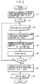
- the flow shown in Fig. 2 is executed by the software of a microcomputer which constitutes the air-flow signal determining means 13 and the characteristic curve calibration circuit 14 of Fig. 1.
- Step 26 the air flow rate signal Mj and the sensor output signal e j are stored as a set of data.
- the preceding steps 23 to 26 are repeated. The number of repetition corresponds to the number j max of the data of the engine speed.
- the above-described calibration can be accomplished in quite a short time.
- the calibration may be conducted with reference to a data map which stores data of the air-flow rate signal Mj in relation to the throttle valve opening ⁇ 0 and the engine speed N j .
- the computation of the air-flow rate signal may be executed on the basis of the assumption that the atmospheric pressure P0 is constant.
- the term of the pressure P0 is omitted from the function f for determining the air-flow rate, so that the formula can be simplified advantageously.
- the function f may be set in the factory at the time of assembly of the engine or, alternatively, determined on the basis of the output signal from the air-flow sensor 5 in the running-in period of the engine.
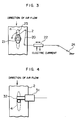
- Fig. 3 illustrates a device for setting the throttle valve opening at ⁇ 0 (full opening).
- the throttle valve 4 is kept in fully closed position by the force of a spring 21, because no tension is applied to the wire 20.
- the shape memory alloy 22 constituting a portion of the wire 20 contracts due to heat generated as a result of supply of electrical power, so as to tense the wire 20, whereby the throttle valve 4 is opened against the force of the spring 21 and is fixed by a stopper 23 at the valve opening ⁇ 0 (full opening).
- Reference numeral 24 denotes the accelerator pedal.
- Fig. 4 shows an arrangement in which the throttle valve opening is controlled by an electric motor 31, comprising a reduction gear 32.
- the throttle valve opening can be set freely by suitably setting the angle of rotation of the rotor of the electric motor.
- the calibration can advantageously be enabled by a simple modification of parts which are originally installed on the engine.
- the intake air-flow rate is determined from the engine speed while setting the throttle valve at a constant opening during idling of the engine. Simultaneously, the air-flow rate is measured with the air-flow sensor. The measuring characteristic of the air-flow sensor is then calibrated on the basis of the intake air-flow rate determined from the engine speed. It is therefore possible to avoid any deterioration in the measuring accuracy of the air-flow sensor, and therefore, to precisely control the air-fuel ratio of the mixture to be fed to the engine. The accuracy of the calibration can be enhanced by adopting, in addition to the speed of the engine, the temperature and the pressure of the ambient air as parameters.
- the use of a shape memory alloy as a part of the member for actuating the throttle valve provides represents simple means for setting the throttle valve to a predetermined opening during idling of the engine.
Landscapes
- Engineering & Computer Science (AREA)
- Chemical & Material Sciences (AREA)
- Combustion & Propulsion (AREA)
- Mechanical Engineering (AREA)
- General Engineering & Computer Science (AREA)
- Analytical Chemistry (AREA)
- Combined Controls Of Internal Combustion Engines (AREA)
- Electrical Control Of Air Or Fuel Supplied To Internal-Combustion Engine (AREA)
- Measuring Volume Flow (AREA)
Claims (6)
- Motorsteuersystem mit- einem Luftstromsensor (5), der im Einlaßkanal (2) einer Brennkraftmaschine angeordnet ist,- einem Drosselventil (4), das stromab vom Luftstromsensor (5) im Einlaßkanal (2) angeordnet ist,- einer Kraftstoffeinspritzvorrichtung (7), die stromab vom Drosselventil (4) angeordnet ist,- einer Luftstromsignalberechnungseinrichtung (6), die Signale (e) vom Luftstromsensor (5) empfängt und das Einlaßluftstromsignal (M) bestimmt gemäß einer ersten Luftstromsignalumwandlungsfunktion (M=g(e)) auf der Basis des Signals vom Luftstromsensor (5), und- einer Luftstromsignalbestimmungseinrichtung (13) zum Bestimmen eines zweiten Luftstromsignals (Mj) gemäß der Motordrehzahl (Nj) und einer gegebenen Drosselventilöffnung (ϑ₀),dadurch gekennzeichnet,
daß eine Eicheinrichtung (14) vorgesehen ist zum Eichen der ersten Luftstromslgnalumwandlungsfunktion (M=g(e)) zum Bestimmen einer neuen ersten Luftstromsignalumwandlungsfunktion (M=g(e)) gemäß dem Wert des Einlaßluftstromdurchsatzes (Mj), der durch die Luftstromsignalbestimmungseinrichtung (13) bestimmt wird während des vom Fahrer gesteuerten Leerlaufs bei zwangsläufig geöffnetem Drosselventil, und zum Liefern der neuen ersten Luftstromumwandlungsfunktion zur Luftstromsignalberechnungseinrichtung (6). - System nach Anspruch 1,
dadurch gekennzeichnet,
daß die Luftstromsignalbestimmungseinrichtung (13) den Einlaßluftstromdurchsatz (Mj) gemäß einer zweiten Luftstromsignalumwandlungsfunktion (Mj=f(Nj, ϑ₀)) berechnet. - System nach Anspruch 1,
dadurch gekennzeichnet,
daß die Luftstromsignalbestimmungseinrichtung (13) den Einlaßluftstromdurchsatz (Mj) in Abhängigkeit von der Drosselventilöffnung (ϑ₀) und der Motordrehzahl (Mj) aus einer Datenliste liest. - System nach einem der Ansprüche 1 bis 3,
dadurch gekennzeichnet,
daß die Luftstromsignalbestimmungseinrichtung (13) den Luftstromdurchsatz (Mj) bestimmt unter Verwendung der Temperatur (T₀) und des Drucks (P₀) der Umgebungsluft als Parameter. - System nach einem der Ansprüche 1 bis 4,
gekennzeichnet durch
eine Einrichtung zum Einstellen des Drosselventils (4) auf eine gegebene Öffnung (ϑ₀) mit- einer Feder (21) zum Schließen des Drosselventils (4) während des Leerlaufzustands der Brennkraftmaschine,- einem Draht (20), der das Drosselventil (4) mit einem Gaspedal (24) so verbindet, daß die Öffnung (ϑ₀) des Drosselventils (4) durch das Gaspedal (24) geändert werden kann, wobei der Draht (20) an seinem Mittelteil abgeschnitten ist, und- einer Memory-Legierung (22), die zwischen den abgeschnittenen Enden des Drahts (20) angeschlossen ist, wobei die Memory-Legierung (22) steuerbar ist, um während des Leerlaufzustandss der Brennkraftmaschine das Drosselventil (4) wahlweise ganz zu öffnen. - System nach einem der Ansprüche 1 bis 5,
dadurch gekennzeichnet,
daß die Einrichtung (14) die erste Luftstromsignal umwandlungsfunktion (M=g(e)) korrigiert, wenn die Differenz zwischen dem Wert des durch die Luftstrom signalberechnungseinrichtung (6) bestimmten Einlaß luftstromsignals (M) und des durch die Luftstromsignalbestimmungseinrichtung (13) bestimmten Luftstrom signals (Mj) einen gegebenen Wert übersteigt.
Applications Claiming Priority (2)
| Application Number | Priority Date | Filing Date | Title |
|---|---|---|---|
| JP10659288 | 1988-04-28 | ||
| JP106592/88 | 1988-04-28 |
Publications (3)
| Publication Number | Publication Date |
|---|---|
| EP0339638A2 EP0339638A2 (de) | 1989-11-02 |
| EP0339638A3 EP0339638A3 (en) | 1990-02-07 |
| EP0339638B1 true EP0339638B1 (de) | 1993-01-20 |
Family
ID=14437449
Family Applications (1)
| Application Number | Title | Priority Date | Filing Date |
|---|---|---|---|
| EP89107641A Expired - Lifetime EP0339638B1 (de) | 1988-04-28 | 1989-04-27 | Steuersystem einer Brennkraftmaschine |
Country Status (4)
| Country | Link |
|---|---|
| US (1) | US4986244A (de) |
| EP (1) | EP0339638B1 (de) |
| KR (1) | KR930000347B1 (de) |
| DE (1) | DE68904463T2 (de) |
Families Citing this family (20)
| Publication number | Priority date | Publication date | Assignee | Title |
|---|---|---|---|---|
| DE3729635A1 (de) * | 1987-09-04 | 1989-03-16 | Bosch Gmbh Robert | Einstellsystem (steuerung- und/oder regelungssystem) fuer kraftfahrzeuge |
| DE3925377A1 (de) * | 1989-08-01 | 1991-02-07 | Bosch Gmbh Robert | Verfahren zur messfehlerkorrektur eines heissfilm-luftmassenmessers |
| JP2787492B2 (ja) * | 1989-12-15 | 1998-08-20 | マツダ株式会社 | エンジンの燃料制御装置 |
| JPH03233157A (ja) * | 1990-02-06 | 1991-10-17 | Mitsubishi Electric Corp | 内燃機関の燃料制御装置 |
| DE4009922C2 (de) * | 1990-03-28 | 2000-01-20 | Mannesmann Vdo Ag | Verfahren und Anordnung zur Ermittlung der tatsächlichen Luftdichte des Ansaug-Luftmassenstroms einer Brennkraftmaschine |
| US5465617A (en) * | 1994-03-25 | 1995-11-14 | General Motors Corporation | Internal combustion engine control |
| DE4430324C1 (de) * | 1994-08-26 | 1996-10-10 | Vdo Schindling | Saugrohr |
| DE19508641A1 (de) * | 1994-12-31 | 1996-07-04 | Bosch Gmbh Robert | Einrichtung zur Lasterfassung bei einer Brennkraftmaschine mit Turbolader |
| US5862995A (en) * | 1996-04-01 | 1999-01-26 | Diesel Technology Company | High pressure fluid passage sealing for internal combustion engine fuel injectors and method of making same |
| DE19636451B4 (de) * | 1996-09-07 | 2010-06-10 | Robert Bosch Gmbh | Einrichtung zum Steuern der einer Brennkraftmaschine zuzuführenden Kraftstoffmenge |
| CN1096552C (zh) * | 1997-09-17 | 2002-12-18 | 罗伯特·博施有限公司 | 控制内燃机中通过节气阀气体流的方法及装置 |
| DE10039785B4 (de) * | 2000-08-16 | 2014-02-13 | Robert Bosch Gmbh | Verfahren und Vorrichtung zum Betreiben einer Brennkraftmaschine |
| JP3938670B2 (ja) * | 2000-09-14 | 2007-06-27 | 本田技研工業株式会社 | 燃料噴射制御装置 |
| US6756571B2 (en) * | 2002-10-17 | 2004-06-29 | Hitachi, Ltd. | System and method for compensation of contamination of a heated element in a heated element gas flow sensor |
| US7021284B2 (en) * | 2004-08-31 | 2006-04-04 | Delphi Technologies, Inc. | Method and apparatus for minimizing engine air tip-in noise |
| DE102007036105B4 (de) * | 2007-08-01 | 2015-02-12 | Audi Ag | Verfahren und Vorrichtung zum Erkennen von Modifikationen einen Ladedrucksensor eines Kraftfahrzeugs betreffend |
| US7856967B2 (en) * | 2008-07-17 | 2010-12-28 | Honda Motor Co., Ltd. | Method of determining ambient pressure for fuel injection |
| GB2503219A (en) * | 2012-06-18 | 2013-12-25 | Gm Global Tech Operations Inc | Method of operating an internal combustion engine |
| WO2017156174A1 (en) | 2016-03-08 | 2017-09-14 | K&N Engineering, Inc. | Aircharger air intake system and method |
| US10718300B2 (en) | 2016-03-09 | 2020-07-21 | K&N Engineering, Inc. | High performance air intake system |
Citations (1)
| Publication number | Priority date | Publication date | Assignee | Title |
|---|---|---|---|---|
| GB2046950A (en) * | 1979-04-02 | 1980-11-19 | Honda Motor Co Ltd | Engine controlling system |
Family Cites Families (9)
| Publication number | Priority date | Publication date | Assignee | Title |
|---|---|---|---|---|
| DE2750050C2 (de) * | 1977-11-09 | 1983-12-08 | Robert Bosch Gmbh, 7000 Stuttgart | Einrichtung zur Luftmengenmessung |
| JPS6047462B2 (ja) * | 1978-06-02 | 1985-10-22 | 株式会社日立製作所 | 電子制御燃料噴射装置の吸入空気量計測装置 |
| JPS59190624A (ja) * | 1983-04-13 | 1984-10-29 | Hitachi Ltd | 吸入空気流量計 |
| US4644474A (en) * | 1985-01-14 | 1987-02-17 | Ford Motor Company | Hybrid airflow measurement |
| JPS6263285A (ja) * | 1985-09-12 | 1987-03-19 | Toshiba Corp | 気流調節用開閉装置 |
| JPS6278449A (ja) * | 1985-10-02 | 1987-04-10 | Mitsubishi Electric Corp | 内燃機関の燃料噴射制御装置 |
| JPH0637863B2 (ja) * | 1986-10-02 | 1994-05-18 | 株式会社ユニシアジェックス | 内燃機関の電子制御燃料噴射装置 |
| JPS63215844A (ja) * | 1987-03-05 | 1988-09-08 | Mikuni Kogyo Co Ltd | エンジンのスロットルバルブ制御装置 |
| JPH0638052B2 (ja) * | 1987-05-08 | 1994-05-18 | 株式会社ユニシアジェックス | 内燃機関の吸入空気流量計測装置 |
-
1989
- 1989-04-19 KR KR1019890005148A patent/KR930000347B1/ko not_active Expired - Fee Related
- 1989-04-26 US US07/343,440 patent/US4986244A/en not_active Expired - Lifetime
- 1989-04-27 DE DE8989107641T patent/DE68904463T2/de not_active Expired - Lifetime
- 1989-04-27 EP EP89107641A patent/EP0339638B1/de not_active Expired - Lifetime
Patent Citations (1)
| Publication number | Priority date | Publication date | Assignee | Title |
|---|---|---|---|---|
| GB2046950A (en) * | 1979-04-02 | 1980-11-19 | Honda Motor Co Ltd | Engine controlling system |
Also Published As
| Publication number | Publication date |
|---|---|
| KR900016600A (ko) | 1990-11-14 |
| KR930000347B1 (ko) | 1993-01-16 |
| EP0339638A2 (de) | 1989-11-02 |
| US4986244A (en) | 1991-01-22 |
| DE68904463D1 (de) | 1993-03-04 |
| DE68904463T2 (de) | 1993-06-03 |
| EP0339638A3 (en) | 1990-02-07 |
Similar Documents
| Publication | Publication Date | Title |
|---|---|---|
| US4986244A (en) | Internal combustion engine | |
| US6088661A (en) | Ambient temperature learning algorithm for automotive vehicles | |
| US4783996A (en) | Direct-heated flow measuring apparatus | |
| JPH0968403A (ja) | スロットルバルブ開度センサ | |
| US6813570B2 (en) | Optimized convection based mass airflow sensor circuit | |
| KR930001729B1 (ko) | 열선식 유속 검출장치 | |
| JPS626093B2 (de) | ||
| US20030070494A1 (en) | Air flow meter | |
| KR100491488B1 (ko) | 열형유량측정장치및그온도오차보정수단 | |
| US6508117B1 (en) | Thermally balanced mass air flow sensor | |
| EP1742025B1 (de) | Thermischer Durchflussmesser | |
| JPH03252529A (ja) | 熱式空気流量計及び該流量計を備えた内燃機関 | |
| JP4279130B2 (ja) | 発熱抵抗体式流体流量測定装置 | |
| EP0347218B1 (de) | Luftdurchfluss-Dosiergerät für Brennkraftmaschinen | |
| EP0354649A2 (de) | Eng gekoppelte Anordnung von Massen-Luftdurchflussmesser und Drosselklappe | |
| EP0156358A2 (de) | Verfahren und Vorrichtung zur elektronischen Steuerung der Kraftstoffeinspritzung einer Brennkraftmaschine | |
| JP3105609B2 (ja) | 発熱抵抗体式空気流量計 | |
| JPH06265385A (ja) | 空気流量測定装置 | |
| JPH0230945A (ja) | 内燃機関 | |
| JPH07166948A (ja) | 内燃機関の制御装置 | |
| JP3047616B2 (ja) | 内燃機関の燃料噴射量制御装置 | |
| JPH1048016A (ja) | 発熱抵抗体式空気流量測定装置および内燃機関の燃料噴射制御システム | |
| JPH1137815A (ja) | 発熱抵抗式流量測定装置およびその温度誤差補正手段 | |
| JP2702940B2 (ja) | 燃料供給装置の校正方法 | |
| JP2665792B2 (ja) | 熱式流量センサの信号処理方法 |
Legal Events
| Date | Code | Title | Description |
|---|---|---|---|
| PUAI | Public reference made under article 153(3) epc to a published international application that has entered the european phase |
Free format text: ORIGINAL CODE: 0009012 |
|
| AK | Designated contracting states |
Kind code of ref document: A2 Designated state(s): DE FR GB |
|
| PUAL | Search report despatched |
Free format text: ORIGINAL CODE: 0009013 |
|
| AK | Designated contracting states |
Kind code of ref document: A3 Designated state(s): DE FR GB |
|
| 17P | Request for examination filed |
Effective date: 19900209 |
|
| 17Q | First examination report despatched |
Effective date: 19910207 |
|
| GRAA | (expected) grant |
Free format text: ORIGINAL CODE: 0009210 |
|
| AK | Designated contracting states |
Kind code of ref document: B1 Designated state(s): DE FR GB |
|
| REF | Corresponds to: |
Ref document number: 68904463 Country of ref document: DE Date of ref document: 19930304 |
|
| ET | Fr: translation filed | ||
| PLBE | No opposition filed within time limit |
Free format text: ORIGINAL CODE: 0009261 |
|
| STAA | Information on the status of an ep patent application or granted ep patent |
Free format text: STATUS: NO OPPOSITION FILED WITHIN TIME LIMIT |
|
| 26N | No opposition filed | ||
| REG | Reference to a national code |
Ref country code: GB Ref legal event code: IF02 |
|
| PGFP | Annual fee paid to national office [announced via postgrant information from national office to epo] |
Ref country code: GB Payment date: 20080328 Year of fee payment: 20 |
|
| PGFP | Annual fee paid to national office [announced via postgrant information from national office to epo] |
Ref country code: DE Payment date: 20080606 Year of fee payment: 20 |
|
| PGFP | Annual fee paid to national office [announced via postgrant information from national office to epo] |
Ref country code: FR Payment date: 20080319 Year of fee payment: 20 |
|
| REG | Reference to a national code |
Ref country code: GB Ref legal event code: PE20 Expiry date: 20090426 |
|
| PG25 | Lapsed in a contracting state [announced via postgrant information from national office to epo] |
Ref country code: GB Free format text: LAPSE BECAUSE OF EXPIRATION OF PROTECTION Effective date: 20090426 |