EP0340478A1 - Pneumatisches Ventil zur Steuerung von Druckluftströmen - Google Patents
Pneumatisches Ventil zur Steuerung von Druckluftströmen Download PDFInfo
- Publication number
- EP0340478A1 EP0340478A1 EP89106251A EP89106251A EP0340478A1 EP 0340478 A1 EP0340478 A1 EP 0340478A1 EP 89106251 A EP89106251 A EP 89106251A EP 89106251 A EP89106251 A EP 89106251A EP 0340478 A1 EP0340478 A1 EP 0340478A1
- Authority
- EP
- European Patent Office
- Prior art keywords
- piston
- working
- control
- pneumatic valve
- valve according
- Prior art date
- Legal status (The legal status is an assumption and is not a legal conclusion. Google has not performed a legal analysis and makes no representation as to the accuracy of the status listed.)
- Granted
Links
- 230000005291 magnetic effect Effects 0.000 claims abstract description 7
- 230000005294 ferromagnetic effect Effects 0.000 claims abstract description 3
- 238000007789 sealing Methods 0.000 claims description 4
- 238000009423 ventilation Methods 0.000 claims 1
- 239000000696 magnetic material Substances 0.000 description 1
- 230000035939 shock Effects 0.000 description 1
Images

Classifications
-
- F—MECHANICAL ENGINEERING; LIGHTING; HEATING; WEAPONS; BLASTING
- F16—ENGINEERING ELEMENTS AND UNITS; GENERAL MEASURES FOR PRODUCING AND MAINTAINING EFFECTIVE FUNCTIONING OF MACHINES OR INSTALLATIONS; THERMAL INSULATION IN GENERAL
- F16K—VALVES; TAPS; COCKS; ACTUATING-FLOATS; DEVICES FOR VENTING OR AERATING
- F16K31/00—Actuating devices; Operating means; Releasing devices
- F16K31/02—Actuating devices; Operating means; Releasing devices electric; magnetic
- F16K31/06—Actuating devices; Operating means; Releasing devices electric; magnetic using a magnet, e.g. diaphragm valves, cutting off by means of a liquid
- F16K31/08—Actuating devices; Operating means; Releasing devices electric; magnetic using a magnet, e.g. diaphragm valves, cutting off by means of a liquid using a permanent magnet
- F16K31/086—Actuating devices; Operating means; Releasing devices electric; magnetic using a magnet, e.g. diaphragm valves, cutting off by means of a liquid using a permanent magnet the magnet being movable and actuating a second magnet connected to the closing element
-
- Y—GENERAL TAGGING OF NEW TECHNOLOGICAL DEVELOPMENTS; GENERAL TAGGING OF CROSS-SECTIONAL TECHNOLOGIES SPANNING OVER SEVERAL SECTIONS OF THE IPC; TECHNICAL SUBJECTS COVERED BY FORMER USPC CROSS-REFERENCE ART COLLECTIONS [XRACs] AND DIGESTS
- Y10—TECHNICAL SUBJECTS COVERED BY FORMER USPC
- Y10T—TECHNICAL SUBJECTS COVERED BY FORMER US CLASSIFICATION
- Y10T137/00—Fluid handling
- Y10T137/8158—With indicator, register, recorder, alarm or inspection means
- Y10T137/8326—Fluid pressure responsive indicator, recorder or alarm
-
- Y—GENERAL TAGGING OF NEW TECHNOLOGICAL DEVELOPMENTS; GENERAL TAGGING OF CROSS-SECTIONAL TECHNOLOGIES SPANNING OVER SEVERAL SECTIONS OF THE IPC; TECHNICAL SUBJECTS COVERED BY FORMER USPC CROSS-REFERENCE ART COLLECTIONS [XRACs] AND DIGESTS
- Y10—TECHNICAL SUBJECTS COVERED BY FORMER USPC
- Y10T—TECHNICAL SUBJECTS COVERED BY FORMER US CLASSIFICATION
- Y10T137/00—Fluid handling
- Y10T137/8593—Systems
- Y10T137/86493—Multi-way valve unit
- Y10T137/86574—Supply and exhaust
- Y10T137/86582—Pilot-actuated
Definitions
- the invention relates to a pneumatic valve for controlling compressed air flows with contactless control.
- a signal is to be derived from a working piston, for this purpose to start from a preferably fixed cylinder, which consists of a non-magnetic material and a permanent magnet located on the piston, because fewer mechanical problems are to be overcome, and thus Read tubes and other sensors reacting to a magnetic field can be controlled. If a further pneumatic valve, which works in the pressure range from 1 to 8 bar, is to be activated, a magnetically actuated, pneumatic signal transmitter must be used, with which the load-switching pneumatic valve is activated.
- the pneumatic valve according to the preamble of claim 1 is characterized in that a pivotably mounted single or double lever is equipped on one or both sides of the pivot axis with a permanent magnet and by means of a feedable ferromagnetic or magnetic switching part via a plunger to close or Opening a control nozzle causes the air flow via a control piston to a working piston for closing or opening.
- a pivotably mounted single or double lever is equipped on one or both sides of the pivot axis with a permanent magnet and by means of a feedable ferromagnetic or magnetic switching part via a plunger to close or Opening a control nozzle causes the air flow via a control piston to a working piston for closing or opening.
- permanent magnets When permanent magnets are arranged on both sides of the swivel axis, they are preferably connected via a magnetic yoke, arranged in opposite poles, so that a magnet which can be supplied outside the valve body as a switching part attracts one permanent magnet on the double lever and repels the other, the switching magnet being able to be arranged as a piston in an antimagnetic cylinder is.
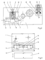
- both a control nozzle 2 with a lever circuit as a lever arm or as a double lever 3 and the control piston 4 with a working piston 5 and a function display 6 are provided in a base body 1.
- the control nozzle 2 is supplied with compressed air when the actuating tappet 7 is lifted from the open seal 8 from 9 as a branch of the main line 10, this opening the control nozzle 2 via the connecting channel 11 to the control piston 4 for actuating the working piston 5 and thus releasing the compressed air Main line 10 is guided to the outlet pipe 12.
- the lever arm is provided, here as a double lever 3, which is equipped on both sides of its pivot axis 13 with a permanent magnet 14 and 15 and, in the case of switching magnets 17 that can be supplied to the sensor surface 16, by pivoting the double lever 3, the plunger 7 for closing or opening the control nozzle 2 moves.
- a permanent magnet 14 and 15 instead of two magnets 14 and 15, it is also possible to provide only one, for example on a lever arm, with the delivery then can be done via the switching magnet 17 and the resetting by means of spring tension.
- the two permanent magnets 14 and 15 are connected here on both sides of the pivot axis 13 via a magnetic yoke 18 and are arranged correspondingly with opposite poles.
- the opening or closing of the nozzle 2 is effected as a switching part by magnets 17 which can be supplied outside of the valve body (base body 1) and which can be arranged, for example, as a piston in an antimagnetic cylinder.
- the compressed air is hereby passed via 11 to the control piston 4, which has a larger sealing piston area than the working piston 5 with a smaller piston area connected via the shaft 19, which piston piston is thus opened against spring action 20 and releases the compressed air P from the main line 10 to the outlet port 12. where this is then available as working air A.
- the function indicator 6 is a piston 23, which extends against the spring 25 when the working pressure A is present via the line 24 and thus indicates the valve function.
- the vent 27 is closed by means of the seal 8 on the collar 28, the control piston 4 moves in the direction of the arrow 23 and closes the vent on the annular surface 21, which opens into the channel 22.
- the air flow P can flow past the valve seat 29 through the channel 24 to the outlet A.
Landscapes
- Engineering & Computer Science (AREA)
- General Engineering & Computer Science (AREA)
- Mechanical Engineering (AREA)
- Fluid-Driven Valves (AREA)
- Magnetically Actuated Valves (AREA)
- Multiple-Way Valves (AREA)
- Mechanically-Actuated Valves (AREA)
Abstract
Description
- Die Erfindung bezieht sich auf ein pneumatisches Ventil zur Steuerung von Druckluftströmen mit berührungsloser Ansteuerung.
- Es ist bekannt, wenn im Bereich der Pneumatik von einem Arbeitskolben ein Signal abgeleitet werden soll, hierzu von einem vorzugsweise feststehenden Zylinder auszugehen, welcher dabei aus einem nichtmagnetischen Material und am Kolben befindlichen Permanentmagnet besteht, weil dabei weniger mechanische Probleme zu bewältigen sind, und damit Readröhren und andere auf ein Magnetfeld reagierende Sensoren angesteuert werden. Soll hierbei ein weiteres Pneumatikventil, das im Druckbereich von 1 bis 8 bar arbeitet, angesteuert werden, so muß ein magnetisch betätigter, pneumatischer Signalgeber eingesetzt werden, mit dem das lastschaltende Pneumatikventil angesteuert wird. Dabei ist nachteilig, daß für den Sensor eine eigene Luftversorgung mit einem Druck von < 0,25 bar benötigt wird und diese Luftversorgung einen hohen Reinheitsgrad aufweisen muß, da sonst die kleinen Düsen bei den geringen Drücken leicht verstopfen. Hinzu kommt, daß die bekannten Pneumatiksensoren schockempfindlich sind und einen dauernden Luftverbrauch von ca. 2 l/min. haben.
- Es ist nun Aufgabe der Erfindung ein pneumatisches Ventil zu schaffen, das berührungslos angesteuert wird und hohe Arbeitsdrücke ohne Zwischenverstärker schalten kann.
- Zur Lösung dieser Aufgabe kennzeichnet sich das pneumatische Ventil nach dem Oberbegriff von Anspruch 1 dadurch, daß ein verschwenkbar gelagerter Einfach- oder Doppelhebel ein- oder beidseits der Schwenkachse mit einem Dauermagneten bestückt ist und mittels zuführbarem ferromagnetischen oder magnetischen Schaltteil über einen Stößel das Verschließen bzw. Öffnen einer Steuerdüse bewirkt, deren Luftstrom über einen Steuerkolben einem Arbeitskolben zum Schließen bzw. Öffnen dient. Hierdurch wird ein Ventil geschaffen, welches die berührungslose Sensorfunktion, die Verstärkerfunktion und das Arbeitsventil mit Funktionsanzeige in einer Baugruppe vereinigt und keine zusätzliche Steuerluftversorgung benötigt.
- Bei Anordnung von Dauermagneten beidseits der Schwenkachse sind diese vorzugsweise über ein Magnetjoch verbunden, gegenpolig angeordnet, so daß ein außerhalb des Ventilkörpers zuführbarer Magnet als Schaltteil den einen Dauermagneten auf dem Doppelhebel anzieht und den anderen abstößt, wobei der Schaltmagnet als Kolben in einem antimagnetischen Zylinder anordenbar ist.
- Eine bevorzugte Ausführungsform des Ventils gemäß der Erfindung ist beispielsweise in der Zeichnung dargestellt und nachfolgend beschrieben und zwa zeigen:
- Fig. 1 eine Draufsicht auf die Gesamtanordnung mit Schnitt durch das Arbeitsventil,
- Fig. 2 eine Seitenansicht hierzu mit Schnitt durch die Steuerdüse mit Hebelbetätigung und Funktionsanzeige,
- Fig. 3 eine Rückansicht mit Schnitt durch die Hebelbetätigung und Schaltmagnet.
- Wie aus der Zeichnung ersichtlich wird, ist in einem Grundkörper 1 sowohl eine Steuerdüse 2 mit Hebelschaltung als Hebelarm bzw. als Doppelhebel 3 und der Steuerkolben 4 mit Arbeitskolben 5 sowie eine Funktionsanzeige 6 vorgesehen.
- Die Steuerdüse 2 wird bei abgehobenem Betätigungsstößel 7 über die geöffnete Dichtung 8 von 9 aus als Abzweigung der Hauptleitung 10 mit Druckluft versorgt, wobei diese bei Öffnung der Steuerdüse 2 über den Verbindungskanal 11 zum Steuerkolben 4 zur Betätigung des Arbeitskolbens 5 und damit Freigabe der Druckluft der Hauptleitung 10 an den Ausgangsstutzen 12 geführt wird.
- Zur Betätigung der Steuerdüse 2 ist der Hebelarm, hier als Doppelhebel 3 vorgesehen, welcher beidseits seiner Schwenkachse 13 jeweils mit einem Dauermagneten 14 und 15 bestückt ist und bei zur Sensorfläche 16 zuführbaren Schaltmagneten 17 durch Verschwenken des Doppelhebels 3 den Stößel 7 zum Verschließen bzw. Öffnen der Steuerdüse 2 bewegt. Anstelle von zwei Magneten 14 und 15 kann auch nur einer, z.B. an einem Hebelarm vorgesehen werden, wobei sodann die Zustellung über den Schaltmagneten 17 und die Rückstellung vermittels Federzug erfolgen kann.
- Die beiden Dauermagneten 14 und 15 sind beidseits der Schwenkachse 13 hier über ein Magnetjoch 18 verbunden und entsprechend gegenpolig angeordnet.
- Somit wird durch außerhalb vom Ventilkörper (Grundkörper 1) zuführbaren Magneten 17, welcher beispielsweise als Kolben in einem antimagnetischen Zylinder angeordnet sein kann, als Schaltteil die Öffnung bzw. Schließung der Düse 2 bewirkt. Hiermit wird die Druckluft über 11 zum Steuerkolben 4 geleitet, welcher eine größere Dichtkolbenfläche aufweist, als der über den Schaft 19 verbundene Arbeitskolben 5 mit kleinerer Kolbenfläche, welcher damit gegen Federwirkung 20 geöffnet wird und die Druckluft P von der Hauptleitung 10 zum Ausgangsstutzen 12 freigibt, wo diese sodann als Arbeitsluft A zur Verfügung steht.
- Als Funktionsanzeige 6 dient schließlich ein Kolben 23, welcherbei über die Leitung 24 anliegenden Arbeitsdruck A gegen die Feder 25 ausfährt und so die Ventilfunktion anzeigt.
- In der Ruhestellung, wie sie in Fig. 1 bis 3 dargestellt ist, wird der Raum 26 hinter dem Steuerkolben 4 durch den Kanal 22 ins Freie entlüftet. Der Zylinderraum 27 entlüftet sich durch den Verbindungskanal 11, vorbei an der Dichtung 8 durch die Öffnung 24 in der Atmosphäre.
- Erfolgt ein Arbeitshub, welcher nicht gezeigt ist, wird die Entlüftung von 27 mittels der Dichtung 8 am Bund 28 verschlossen, der Steuerkolben 4 bewegt sich in Richtung des Pfeiles 23 und verschließt an der Ringfläche 21 die Entlüftung, welche in den Kanal 22 mündet. Somit kann der Luftstrom P vorbei am Ventilsitz 29 durch den Kanal 24 zum Ausgang A strömen.
Claims (7)
dadurch gekennzeichnet, daß ein verschwenkbar gelagerter Einfach- oder Doppelhebel ein- oder beidseits der Schwenkachse mit einem Dauermagneten bestückt ist und mittels zuführbarem ferromagnetischen oder magnetischen Schaltteil über einen Stößel das Verschließen bzw. Öffnen einer Steuerdüse bewirkt, deren Luftstrom einem Arbeitskolben zum Schließen bzw. Öffnen dient.
dadurch gekennzeichnet, daß bei Dauermagneten beidseits der Schwenkachse diese vorzugsweise über ein Magnetjoch verbunden, gegenpolig angeordnet sind, so daß ein außerhalb des Ventilkörpers zuführbarer Magnet als Schaltteil den einen Dauermagneten auf dem Doppelhebel anzieht und den anderen abstößt, wobei der Schaltmagnet als Kolben in einem antimagnetischen Zylinder anordenbar ist.
dadurch gekennzeichnet, daß der zugeordnete Arbeitskolben einerseits mit größerer Dichtkolbenfläche von der Steuerdüse beaufschlagbar ist und andererseits mit kleinerer Kolbenfläche gegen Federwirkung und/oder Arbeitsluftdruck die letztere steuert.
dadurch gekennzeichnet, daß bei über einen Schaft verbundenen einerseits größeren Dichtkolben für die Beaufschlagung durch den Steuerluftdruck und andererseits vorgesehenen kleineren Arbeitsluft-Steuerkolben für die Arbeitsdruckluft jeweils nach Durchlaß- oder Verschlußstellung für die Arbeitsdruckluft der Entlüftungsstutzen vom großen Dichtkolben bzw. der Arbeitsdruckstutzen vom kleineren Steuerkolben freigegeben ist.
dadurch gekennzeichnet, daß die Steuerdüse und das Lastventil vom gleichen Preßluftanschluß versorgt wird.
dadurch gekennzeichnet, daß die Steuerdüse mit der Hebelschaltung und der Steuerkolben mit dem Arbeitskolben als Lastventil in einem gemeinsamen Grundkörper aufgenommen sind.
dadurch gekennzeichnet, daß ein Kolben bei anliegendem Arbeitsdruck gegen Federwirkung als Funktionsanzeige ausfahrbar ist.
Priority Applications (1)
| Application Number | Priority Date | Filing Date | Title |
|---|---|---|---|
| AT89106251T ATE81896T1 (de) | 1988-04-16 | 1989-04-08 | Pneumatisches ventil zur steuerung von druckluftstroemen. |
Applications Claiming Priority (2)
| Application Number | Priority Date | Filing Date | Title |
|---|---|---|---|
| DE3812769A DE3812769C2 (de) | 1988-04-16 | 1988-04-16 | Pneumatisches Ventil zur Steuerung von Druckluftströmen |
| DE3812769 | 1988-04-16 |
Publications (2)
| Publication Number | Publication Date |
|---|---|
| EP0340478A1 true EP0340478A1 (de) | 1989-11-08 |
| EP0340478B1 EP0340478B1 (de) | 1992-10-28 |
Family
ID=6352171
Family Applications (1)
| Application Number | Title | Priority Date | Filing Date |
|---|---|---|---|
| EP89106251A Expired - Lifetime EP0340478B1 (de) | 1988-04-16 | 1989-04-08 | Pneumatisches Ventil zur Steuerung von Druckluftströmen |
Country Status (5)
| Country | Link |
|---|---|
| US (1) | US4964424A (de) |
| EP (1) | EP0340478B1 (de) |
| JP (1) | JPH028575A (de) |
| AT (1) | ATE81896T1 (de) |
| DE (1) | DE3812769C2 (de) |
Families Citing this family (3)
| Publication number | Priority date | Publication date | Assignee | Title |
|---|---|---|---|---|
| US6991211B2 (en) * | 2003-12-29 | 2006-01-31 | Robert Altonji | Pneumatically actuated valve |
| DE102005038621B4 (de) * | 2005-08-16 | 2007-09-13 | Bosch Rexroth Ag | Pneumatisches Wegeventil mit mindestens einem Ventilschieber |
| CN102734474A (zh) * | 2012-07-02 | 2012-10-17 | 浙江理工大学 | 一种气动高速开关阀 |
Citations (3)
| Publication number | Priority date | Publication date | Assignee | Title |
|---|---|---|---|---|
| DE2326085A1 (de) * | 1969-04-25 | 1974-12-12 | H Tiefenbach & Co Dr | Selbsthaltendes steuerventil |
| DE2443687A1 (de) * | 1974-09-12 | 1976-04-01 | Siemens Ag | Magnetventil |
| US4046061A (en) * | 1975-12-03 | 1977-09-06 | The Garrett Corporation | Four-way clevis valve and method |
Family Cites Families (11)
| Publication number | Priority date | Publication date | Assignee | Title |
|---|---|---|---|---|
| DE143295C (de) * | 1901-12-24 | 1903-08-12 | General Electric Construction Co. | Elektrische stromzuführungsanlage |
| US2575086A (en) * | 1947-02-14 | 1951-11-13 | Gen Electric | Magnetic valve |
| DE1143391B (de) * | 1956-11-16 | 1963-02-07 | Lee Shih Ying | Fluessigkeits-Steuereinrichtung fuer Servomotoren |
| FR1258366A (fr) * | 1960-03-02 | 1961-04-14 | Rech Etudes Production Sarl | étage primaire à palette et tube de torsion pour distributeur hydraulique à deux étages |
| DE1175553B (de) * | 1960-11-08 | 1964-08-06 | Continental Elektro Ind Ag | Elektro-hydraulischer oder elektro-pneumatischer Stellantrieb mit Verstellmoeglichkeit von Hand |
| US3517699A (en) * | 1967-10-20 | 1970-06-30 | Gen Equip & Mfg | Magnetic-pneumatic proximity switch |
| US3398764A (en) * | 1968-01-22 | 1968-08-27 | Herion Erich | Switch valve, especially magnet valve with sub-divided housing parts which are detachable from each other |
| FR2116863A5 (fr) * | 1970-12-10 | 1972-07-21 | Gratzmuller Jean Louis | Commande hydraulique a deux voies |
| US4137942A (en) * | 1976-07-15 | 1979-02-06 | W-K-M Wellhead Systems, Inc. | Control valve having integral visual indicator for fluid safety systems |
| NL8201105A (nl) * | 1982-03-17 | 1983-10-17 | Beta Bv | Pneumatische schakelaar, bijvoorbeeld voor overdrukbeveiliging. |
| DE3630200A1 (de) * | 1986-09-04 | 1988-03-17 | Rexroth Mannesmann Gmbh | Hydraulisches servoventil |
-
1988
- 1988-04-16 DE DE3812769A patent/DE3812769C2/de not_active Expired - Fee Related
-
1989
- 1989-04-08 EP EP89106251A patent/EP0340478B1/de not_active Expired - Lifetime
- 1989-04-08 AT AT89106251T patent/ATE81896T1/de active
- 1989-04-10 US US07/335,756 patent/US4964424A/en not_active Expired - Fee Related
- 1989-04-17 JP JP1097252A patent/JPH028575A/ja active Pending
Patent Citations (3)
| Publication number | Priority date | Publication date | Assignee | Title |
|---|---|---|---|---|
| DE2326085A1 (de) * | 1969-04-25 | 1974-12-12 | H Tiefenbach & Co Dr | Selbsthaltendes steuerventil |
| DE2443687A1 (de) * | 1974-09-12 | 1976-04-01 | Siemens Ag | Magnetventil |
| US4046061A (en) * | 1975-12-03 | 1977-09-06 | The Garrett Corporation | Four-way clevis valve and method |
Also Published As
| Publication number | Publication date |
|---|---|
| EP0340478B1 (de) | 1992-10-28 |
| DE3812769A1 (de) | 1989-10-26 |
| ATE81896T1 (de) | 1992-11-15 |
| US4964424A (en) | 1990-10-23 |
| JPH028575A (ja) | 1990-01-12 |
| DE3812769C2 (de) | 1995-06-29 |
Similar Documents
| Publication | Publication Date | Title |
|---|---|---|
| EP2004428B1 (de) | Schaltventil | |
| DE3814765C2 (de) | ||
| EP1382907A1 (de) | Vorrichtung zum Regeln des Gasstromes zu einem Brenner | |
| DE4416279A1 (de) | Magnetventil | |
| DE3410795A1 (de) | Elektropneumatischer wandler | |
| EP1959178A2 (de) | Elektromagnetisch zu betätigendes Ventil | |
| EP0846902B1 (de) | Elektropneumatisches Ventil | |
| DE1069972B (de) | ||
| EP3228913B1 (de) | Elektropneumatisches magnetventil | |
| DE4224389A1 (de) | Ventil mit T-förmigem bzw. N-förmigem, wippenartigem Ventilglied | |
| DE102004015661B4 (de) | Elektropneumatisches Ventil, insbesondere Vorsteuerventil für ein pneumatisches Wegeventil | |
| EP0340478B1 (de) | Pneumatisches Ventil zur Steuerung von Druckluftströmen | |
| DE2326085C3 (de) | Durch das Magnetfeld eines äußeren Schaltmagneten betätigte Betätigungsvorrichtung für ein selbsthaltendes Steuerventil | |
| EP2193298B1 (de) | Ventil | |
| EP0056450B1 (de) | Elektropneumatischer Wandler | |
| EP0676916A1 (de) | Vorsteuerventil. | |
| DE19847311A1 (de) | Ventileinrichtung | |
| DE3122120C2 (de) | ||
| DE19710028A1 (de) | Überwachungsvorrichtung für Magnetventile | |
| WO2018121901A1 (de) | Elektromagnetische klappanker-ventilvorrichtung | |
| EP0030283B1 (de) | Betätigungseinrichtung für ein Wegeventil | |
| DE8806867U1 (de) | Elektromagnetisch betätigbares 5/2-Wegeventil | |
| DE29513047U1 (de) | Magnetventil | |
| DE202023102904U1 (de) | Magnetventil mit Druckentlastung und System für ein pneumatisch betriebenes Feldgerät | |
| EP0869286A2 (de) | Elektropneumatisches Wegeventil |
Legal Events
| Date | Code | Title | Description |
|---|---|---|---|
| PUAI | Public reference made under article 153(3) epc to a published international application that has entered the european phase |
Free format text: ORIGINAL CODE: 0009012 |
|
| AK | Designated contracting states |
Kind code of ref document: A1 Designated state(s): AT BE CH FR GB IT LI NL SE |
|
| 17P | Request for examination filed |
Effective date: 19900203 |
|
| 17Q | First examination report despatched |
Effective date: 19910314 |
|
| GRAA | (expected) grant |
Free format text: ORIGINAL CODE: 0009210 |
|
| AK | Designated contracting states |
Kind code of ref document: B1 Designated state(s): AT BE CH FR GB IT LI NL SE |
|
| PG25 | Lapsed in a contracting state [announced via postgrant information from national office to epo] |
Ref country code: NL Effective date: 19921028 Ref country code: BE Effective date: 19921028 |
|
| REF | Corresponds to: |
Ref document number: 81896 Country of ref document: AT Date of ref document: 19921115 Kind code of ref document: T |
|
| ITF | It: translation for a ep patent filed | ||
| GBT | Gb: translation of ep patent filed (gb section 77(6)(a)/1977) |
Effective date: 19930120 |
|
| EN | Fr: translation not filed | ||
| PG25 | Lapsed in a contracting state [announced via postgrant information from national office to epo] |
Ref country code: AT Effective date: 19930408 |
|
| NLV1 | Nl: lapsed or annulled due to failure to fulfill the requirements of art. 29p and 29m of the patents act | ||
| REG | Reference to a national code |
Ref country code: FR Ref legal event code: AR |
|
| PLBE | No opposition filed within time limit |
Free format text: ORIGINAL CODE: 0009261 |
|
| STAA | Information on the status of an ep patent application or granted ep patent |
Free format text: STATUS: NO OPPOSITION FILED WITHIN TIME LIMIT |
|
| ET | Fr: translation filed | ||
| REG | Reference to a national code |
Ref country code: FR Ref legal event code: DS |
|
| 26N | No opposition filed | ||
| EAL | Se: european patent in force in sweden |
Ref document number: 89106251.5 |
|
| PGFP | Annual fee paid to national office [announced via postgrant information from national office to epo] |
Ref country code: GB Payment date: 19960401 Year of fee payment: 8 |
|
| PG25 | Lapsed in a contracting state [announced via postgrant information from national office to epo] |
Ref country code: GB Effective date: 19970408 |
|
| PGFP | Annual fee paid to national office [announced via postgrant information from national office to epo] |
Ref country code: SE Payment date: 19970416 Year of fee payment: 9 |
|
| PGFP | Annual fee paid to national office [announced via postgrant information from national office to epo] |
Ref country code: CH Payment date: 19970425 Year of fee payment: 9 |
|
| GBPC | Gb: european patent ceased through non-payment of renewal fee |
Effective date: 19970408 |
|
| PG25 | Lapsed in a contracting state [announced via postgrant information from national office to epo] |
Ref country code: SE Free format text: LAPSE BECAUSE OF NON-PAYMENT OF DUE FEES Effective date: 19980409 |
|
| PG25 | Lapsed in a contracting state [announced via postgrant information from national office to epo] |
Ref country code: LI Free format text: LAPSE BECAUSE OF NON-PAYMENT OF DUE FEES Effective date: 19980430 Ref country code: CH Free format text: LAPSE BECAUSE OF NON-PAYMENT OF DUE FEES Effective date: 19980430 |
|
| REG | Reference to a national code |
Ref country code: CH Ref legal event code: PL |
|
| EUG | Se: european patent has lapsed |
Ref document number: 89106251.5 |
|
| PG25 | Lapsed in a contracting state [announced via postgrant information from national office to epo] |
Ref country code: IT Free format text: LAPSE BECAUSE OF NON-PAYMENT OF DUE FEES Effective date: 20050408 |
|
| PGFP | Annual fee paid to national office [announced via postgrant information from national office to epo] |
Ref country code: FR Payment date: 20050419 Year of fee payment: 17 |
|
| REG | Reference to a national code |
Ref country code: FR Ref legal event code: ST Effective date: 20061230 |
|
| PG25 | Lapsed in a contracting state [announced via postgrant information from national office to epo] |
Ref country code: FR Free format text: LAPSE BECAUSE OF NON-PAYMENT OF DUE FEES Effective date: 20060502 |