EP0341741B1 - Méthode d'enrouler un film sur une bobine et de charger la bobine et son film dans un magasin et un système pour réaliser cette méthode - Google Patents
Méthode d'enrouler un film sur une bobine et de charger la bobine et son film dans un magasin et un système pour réaliser cette méthode Download PDFInfo
- Publication number
- EP0341741B1 EP0341741B1 EP89108616A EP89108616A EP0341741B1 EP 0341741 B1 EP0341741 B1 EP 0341741B1 EP 89108616 A EP89108616 A EP 89108616A EP 89108616 A EP89108616 A EP 89108616A EP 0341741 B1 EP0341741 B1 EP 0341741B1
- Authority
- EP
- European Patent Office
- Prior art keywords
- spool
- film
- pallet
- film winding
- roll
- Prior art date
- Legal status (The legal status is an assumption and is not a legal conclusion. Google has not performed a legal analysis and makes no representation as to the accuracy of the status listed.)
- Expired - Lifetime
Links
- 238000004804 winding Methods 0.000 title claims description 119
- 238000000034 method Methods 0.000 title claims description 12
- 238000012840 feeding operation Methods 0.000 claims 2
- 210000000078 claw Anatomy 0.000 description 11
- 238000003780 insertion Methods 0.000 description 4
- 230000037431 insertion Effects 0.000 description 4
- 230000005540 biological transmission Effects 0.000 description 3
- 239000002390 adhesive tape Substances 0.000 description 1
- 230000000994 depressogenic effect Effects 0.000 description 1
- 230000009189 diving Effects 0.000 description 1
- 230000002093 peripheral effect Effects 0.000 description 1
- 239000000523 sample Substances 0.000 description 1
Images



Classifications
-
- G—PHYSICS
- G03—PHOTOGRAPHY; CINEMATOGRAPHY; ANALOGOUS TECHNIQUES USING WAVES OTHER THAN OPTICAL WAVES; ELECTROGRAPHY; HOLOGRAPHY
- G03B—APPARATUS OR ARRANGEMENTS FOR TAKING PHOTOGRAPHS OR FOR PROJECTING OR VIEWING THEM; APPARATUS OR ARRANGEMENTS EMPLOYING ANALOGOUS TECHNIQUES USING WAVES OTHER THAN OPTICAL WAVES; ACCESSORIES THEREFOR
- G03B17/00—Details of cameras or camera bodies; Accessories therefor
- G03B17/26—Holders for containing light sensitive material and adapted to be inserted within the camera
-
- Y—GENERAL TAGGING OF NEW TECHNOLOGICAL DEVELOPMENTS; GENERAL TAGGING OF CROSS-SECTIONAL TECHNOLOGIES SPANNING OVER SEVERAL SECTIONS OF THE IPC; TECHNICAL SUBJECTS COVERED BY FORMER USPC CROSS-REFERENCE ART COLLECTIONS [XRACs] AND DIGESTS
- Y10—TECHNICAL SUBJECTS COVERED BY FORMER USPC
- Y10T—TECHNICAL SUBJECTS COVERED BY FORMER US CLASSIFICATION
- Y10T29/00—Metal working
- Y10T29/49—Method of mechanical manufacture
- Y10T29/49826—Assembling or joining
- Y10T29/49828—Progressively advancing of work assembly station or assembled portion of work
- Y10T29/49829—Advancing work to successive stations [i.e., assembly line]
-
- Y—GENERAL TAGGING OF NEW TECHNOLOGICAL DEVELOPMENTS; GENERAL TAGGING OF CROSS-SECTIONAL TECHNOLOGIES SPANNING OVER SEVERAL SECTIONS OF THE IPC; TECHNICAL SUBJECTS COVERED BY FORMER USPC CROSS-REFERENCE ART COLLECTIONS [XRACs] AND DIGESTS
- Y10—TECHNICAL SUBJECTS COVERED BY FORMER USPC
- Y10T—TECHNICAL SUBJECTS COVERED BY FORMER US CLASSIFICATION
- Y10T29/00—Metal working
- Y10T29/49—Method of mechanical manufacture
- Y10T29/49826—Assembling or joining
- Y10T29/49863—Assembling or joining with prestressing of part
- Y10T29/4987—Elastic joining of parts
-
- Y—GENERAL TAGGING OF NEW TECHNOLOGICAL DEVELOPMENTS; GENERAL TAGGING OF CROSS-SECTIONAL TECHNOLOGIES SPANNING OVER SEVERAL SECTIONS OF THE IPC; TECHNICAL SUBJECTS COVERED BY FORMER USPC CROSS-REFERENCE ART COLLECTIONS [XRACs] AND DIGESTS
- Y10—TECHNICAL SUBJECTS COVERED BY FORMER USPC
- Y10T—TECHNICAL SUBJECTS COVERED BY FORMER US CLASSIFICATION
- Y10T29/00—Metal working
- Y10T29/49—Method of mechanical manufacture
- Y10T29/49826—Assembling or joining
- Y10T29/49863—Assembling or joining with prestressing of part
- Y10T29/49874—Prestressing rod, filament or strand
-
- Y—GENERAL TAGGING OF NEW TECHNOLOGICAL DEVELOPMENTS; GENERAL TAGGING OF CROSS-SECTIONAL TECHNOLOGIES SPANNING OVER SEVERAL SECTIONS OF THE IPC; TECHNICAL SUBJECTS COVERED BY FORMER USPC CROSS-REFERENCE ART COLLECTIONS [XRACs] AND DIGESTS
- Y10—TECHNICAL SUBJECTS COVERED BY FORMER USPC
- Y10T—TECHNICAL SUBJECTS COVERED BY FORMER US CLASSIFICATION
- Y10T29/00—Metal working
- Y10T29/53—Means to assemble or disassemble
- Y10T29/53313—Means to interrelatedly feed plural work parts from plural sources without manual intervention
- Y10T29/53365—Multiple station assembly apparatus
-
- Y—GENERAL TAGGING OF NEW TECHNOLOGICAL DEVELOPMENTS; GENERAL TAGGING OF CROSS-SECTIONAL TECHNOLOGIES SPANNING OVER SEVERAL SECTIONS OF THE IPC; TECHNICAL SUBJECTS COVERED BY FORMER USPC CROSS-REFERENCE ART COLLECTIONS [XRACs] AND DIGESTS
- Y10—TECHNICAL SUBJECTS COVERED BY FORMER USPC
- Y10T—TECHNICAL SUBJECTS COVERED BY FORMER US CLASSIFICATION
- Y10T29/00—Metal working
- Y10T29/53—Means to assemble or disassemble
- Y10T29/534—Multiple station assembly or disassembly apparatus
-
- Y—GENERAL TAGGING OF NEW TECHNOLOGICAL DEVELOPMENTS; GENERAL TAGGING OF CROSS-SECTIONAL TECHNOLOGIES SPANNING OVER SEVERAL SECTIONS OF THE IPC; TECHNICAL SUBJECTS COVERED BY FORMER USPC CROSS-REFERENCE ART COLLECTIONS [XRACs] AND DIGESTS
- Y10—TECHNICAL SUBJECTS COVERED BY FORMER USPC
- Y10T—TECHNICAL SUBJECTS COVERED BY FORMER US CLASSIFICATION
- Y10T29/00—Metal working
- Y10T29/53—Means to assemble or disassemble
- Y10T29/53465—Film or tape cartridge
-
- Y—GENERAL TAGGING OF NEW TECHNOLOGICAL DEVELOPMENTS; GENERAL TAGGING OF CROSS-SECTIONAL TECHNOLOGIES SPANNING OVER SEVERAL SECTIONS OF THE IPC; TECHNICAL SUBJECTS COVERED BY FORMER USPC CROSS-REFERENCE ART COLLECTIONS [XRACs] AND DIGESTS
- Y10—TECHNICAL SUBJECTS COVERED BY FORMER USPC
- Y10T—TECHNICAL SUBJECTS COVERED BY FORMER US CLASSIFICATION
- Y10T29/00—Metal working
- Y10T29/53—Means to assemble or disassemble
- Y10T29/53478—Means to assemble or disassemble with magazine supply
Definitions
- This invention relates to a method of winding a photographic roll film such as 16mm film or 35mm film around a spool and loading the roll film-spool assembly into a film magazine, and a system for carrying out the method.
- the spool with the roll film must be delivered from one pickup arm to another pickup arm a plurality of times, and since the spool carrying thereon a roll film is hard to stably hold, trouble is apt to occur during delivery of the spool, which can cause various troubles such as interruption of the assembly line.
- the step of winding the roll film around the spool takes a much longer time than the other steps such as the step of inserting the spool with the roll film into a film magazine, or the step of capping the film magazine. Accordingly, in the known system in which the spool is provided with a roll film and sent to the magazine assembly station one by one, the time required to assemble each film magazine is governed by the time required to wind the roll film around the spool. This is not preferable from the viewpoint of increase in the productivity.
- the primary object of the present invention is to provide a method of winding a photographic roll film around a spool and loading the roll film-spool assembly into a film magazine in which troubles which accompanies delivery of the roll film-spool assembly can be prevented.
- Another object of the present invention is to provide a method of winding a photographic roll film around a spool and loading the roll film-spool assembly into a film magazine in which the effective time required to assemble each film cassette can be shortened.
- Still another object of the present invention is to provide a system for carrying out the method.
- a spool around which a roll film is to be wound is carried by a pallet having a spool holding shaft which holds the spool and rotates the spool under a force transmitted to the spool holding shaft from outside the pallet and a film pinch means which pinches the outer end portion (the leader portion) of the roll film wound around the spool and is moved from station to station in a film cassette assembly line.
- a method of winding a plurality of unexposed photographic roll film around plurality of spools and loading each spool with the wound film into a film magazine as claimed in claim 2 which is similar to the method in accordance with the first aspect of the present invention.
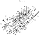
- a first indexing means 10 is rotatable about a shaft 10A, and is provided with four guide rails 11 which are arranged at intervals of 90° about the shaft 10A and extend in parallel to the shaft 10A.
- the shaft 10A is connected to a first indexer driving means 12 and is intermittently rotated in the counterclockwise direction by 90° at intervals of a predetermined time T1.
- a second indexing 13 is provided on the side of the first indexing means 10 opposite to the first indexer driving means 12 and is rotatable about a shaft 13A which is coaxial with the shaft 10A.
- the second indexing means 13 is provided with four guide rails 14 each of which is the same as the guide rail 11 of the first indexing means 10 in cross-sectional shape and adapted to be in alignment with one of the guide rails 11.
- the shaft 13A of the second indexing means 13 is connected to a second indexer driving means 15 and is intermittently rotated in the counterclockwise direction by 90° at intervals of a predetermined time T2 which is one third of the predetermined time T1. That is, the first indexing means 10 is rotated once every time the second indexing means 13 is rotated three times, or the first indexing means 10 is rotated by 90° every time the second indexing means 13 is rotated by 270°.
- a plurality of film winding pallets 20 (20A, 20B, 20C ⁇ ) are slid along the guide rails 11 and 14 in the longitudinal direction thereof in engagement with the guide rails.
- Reference numerals 20A, 20B, 20C and so on will sometimes be used in order to denote the film winding pallets 20 per se which are positioned in particular positions and sometimes be used in order to denote the particular positions, hereinbelow.
- the film winding pallet 20 has a carriage body 20a provided on the lower surface thereof with an engagement groove 21 which is adapted to be engaged with the guide rails 11 and 14 so that the carriage body 20a can slide along the rails.
- a bearing unit (not shown) is provided in the engagement groove 21 in order to facilitate the slide of the carriage body 20a along the rails 11 and 14.
- the film winding pallet 20 is provided with a spool holding shaft 22 which extends in parallel to the the engagement groove 21.
- the spool holding shaft 22 is provided with a collet chuck 22A on the front end thereof.
- the collet chuck 22A is given a work holding force by a coil spring 24, and the transmission of the work holding force to the chuck 22A is interrupted when a spool release lever 25 is depressed.
- the spool holding shaft 22 is connected, by way of a rotation transmission mechanism (not shown), to a rotation inputting shaft 23 which projects from a side of the carriage body 20a.
- the rotation inputting shaft 23 is provided with a claw clutch 23A on the outer end thereof.
- a pair of brake members 27 project outside from the side of the carriage body 20a and are urged outward by springs 26. Each brake member 27 is connected to a brake pad (not shown) and normally presses it against the spool holding shaft 22 so as to restrain the rotation of spool holding shaft 22. When pushed inward by an external force, the brake member 27 removes the brake pad from the spool holding shaft 22 and permits the spool holding shaft 22 to rotate freely.
- a pair of film pinch arms 29A and 29B are mounted on the top of the carriage body 20a so that they can rotate in a horizontal plane respectively about pivot shafts 28A and 28B.
- the film pinch arms 29A and 29B are moved between an open position shown in Figure 2 where they are positioned away from each other and a closure position above and in front of the collet chuck 22A where they abut against each other.
- the arms 29A and 29B forms a toggle mechanism and held in the open position or the closure position under the force of a toggle spring 30.
- the arms 29A and 29B are positioned one of the positions by operation of an arm opening and closing lever 31.
- a hook roller 32 which is used when the film winding pallet 20 is moved is provided in the vicinity of the arm opening and closing lever 31.
- the film winding pallet 20 chucks the longer boss portion 35E of a spool 35 for 35mm film ( Figure 3) with the collet chuck 22A in a manner which will be described later.
- three film winding pallets 20 with the spools 35 chucked are positioned on the uppermost one of the guide rails 11 of the first indexing means 10 as shown in Figure 1.
- the three film winding pallets 20 are spaced from each other by a predetermined distance and arranged in line so that the spool holding shafts 22 of the respective film winding pallets 20 are in alignment with each other in parallel to the rail 11.
- a roll film of a predetermined length is fed to each of the three spools 35 and an end of the roll film is brought into engagement with the spool 35.
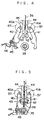
- the operation of the engaging the roll film with the spool 35 will be described, hereinbelow, with reference to Figures 4 to 6 which show in detail the mechanism for the purpose.
- the mechanism is omitted in Figure 1.
- Three pairs of clampers 40 and 41 are disposed so that one pair of clampers 40 and 41 are disposed on opposite sides of each spool 35 held by the film winding pallet 20 as shown in Figure 4.
- the clampers 40 and 41 are pivoted toward each other and clamp the spool 35 therebetween as shown in Figure 5 when the film winding pallet 20 holding the spool 35 is positioned in a predetermined position.
- the spool 35 is held so that its cassette slit 35A ( Figure 3) opens upward. Then a roll film 36 which has been held above a pair of guide plates 44 with its trailing end portion 36B directed downward is dropped between the guide plates 44 and a pair of feed rollers 42 and 43 below the guide plates 44 are rotated as shown by the arrows in Figure 5, whereby the trailing end portion 36B of the roll film 36 is inserted into the slit 35A of the spool 35.
- the trailing end portion 36B of the roll film 36 has been cut into the shape shown in Figure 7 and is provided with a pair of engagement holes 36A.
- the spool 35 is provided with a pair of engagement claws 35B in the slit 35A.
- Each engagement claw 35B has an inclined surface and hooked tip portion, and the engagement holes 36A are brought into engagement with the engagement claws 35B as the trailing end portion 36B of the roll film 36 is inserted into the slit 35A as shown in Figure 7.
- the trailing end portion 36B is connected to the spool 35.
- the trailing end portion 36B partly projects downward from the lower opening of the slit 35A (e.g., by 1mm).
- the projecting part of the trailing end portion 36B pushes downward a film insertion detecting lever 45 which is shown in Figures 4 and 5.
- the downward movement of the lever 45 is detected by a photoelectric sensor 46.
- FIG 8 shows winding driving means which rotates the spools 35 in order to wind the roll films 36 around the spools 35.
- the winding driving means is omitted in Figure 1.
- a table 50 is moved along a pair of guide rails 51 to the side of the first indexing means 10 as shown in Figure 8.
- Three winding driving shafts 52 are located on the table 50.
- Each driving shaft 52 is connected to the output shaft of a servomotor 54 by way of a clutch-brake unit 53.
- Each driving shaft 52 has a claw clutch (not shown) on the free end face thereof and is opposed to the rotation inputting shaft 23 of one of the film winding pallets 20.
- a pinch arm driving member 60 is moved in the direction parallel to the guide rails 11.
- the pinch arm driving member 60 has three abutment portions (not shown) which are adapted to abut against the arm opening and closing levers 31 of the respective film winding pallets 20, and when the pinch arm diving member 60 is moved in the direction parallel to the guide rails 11, each projection urges the corresponding arm opening and closing lever 31 to bring the film pinch arms 29A and 29B of the corresponding film winding pallet 20 to said closure position.
- the leader portion of the roll film 36 is pinched therebetween.
- each spool 35 is prevented from being reversed under the resiliency of the roll film 36 so as to unroll the roll film 36.
- the first indexer driving means 12 rotates the first indexing means 10 by 90°.
- the second indexing means 13 is also rotated by 90°. Accordingly, the three film winding pallets 20 which have been in the positions indicated at 20F, 20G and 20H in Figure 1 are moved to the positions indicated at 20C, 20D and 20E.
- Another three film winding pallets 20 have been positioned on the guide rail 11 which is in the uppermost position after the first indexing means 10 is thus rotated by 90° in the manner which will become apparent later, and the roll films 36 are wound around the spools 35 held by the another three film winding pallets 20 in the manner described above.
- a shifter 61 extends in parallel to the guide rails 11 and is opposed to the film winding pallets 20C to 20E.
- the shifter 61 comprises a guide rod 61a and three engagement members 62 which are slidable on the guide rod 61a and rotatable about the longitudinal axis of the guide rod 61a together with the guide rod 61a.
- the three engagement members 62 are spaced from each other by a distance equal to the distance between adjacent two film winding pallets 20.
- the engagement members 62 are moved along the guide rod 61a by a distance equal to the space between the film winding pallets and pushes the film winding pallets 20C to 20E toward the guide rails 14 of the second indexing means 13 so that the pallet which has been in the position 20C is delivered to one of the guide rails 14 as shown by the chained line in Figure 1 and the pallets which have been respectively in the positions 20D and 20E are moved to the positions 20C and 20D.
- the engagement member 62 nearest to the guide rails 14 is further moved by a predetermined distance L after the other engagement members 62 are stopped and moves the film winding pallet 20C to the position shown by the chained line.
- a magazine assembly system 100 is disposed beside the guide rails 14.
- the magazine assembly system 100 comprises a vertical indexing system 102 which intermittently rotates about a shaft 101 in a vertical plane perpendicular to the longitudinal axis of the guide rails 14.
- the indexing system 102 holds a magazine barrel plate 150 in an unrolled state in a position opposed to the film winding pallet 20 delivered to the guide rail 14 as shown in Figure 10.
- the spool 35 with the roll film 36 held by the film winding pallet 20 is moved in the longitudinal direction thereof above the magazine barrel plate 150, and the magazine barrel plate 150 is rolled so that opposite end portions 150A and 150B thereof are superposed one on the other and form the cassette slit.
- the engagement member 62 nearest to the guide rails 14 is returned by said predetermined distance L trailing the film winding pallet 20C on the guide rail 14.
- the film winding pallet 20C is still on the guide rail even after it is reversed by the distance L.
- the other two engagement member 62 are kept stationary.
- a spool releasing member 64 and a film releasing member 65 ( Figure 10) have been positioned in positions where they respectively interfere with the spool release lever 25 and the arm opening and closing lever 31.
- the releasing members 64 and 65 abut against the spool release lever 25 and the arm opening and closing lever 31 when the film winding pallet 20C is reversed, thereby causing the collet chuck 22A to release the spool 35 and moving the film pinch arms 29A and 29B to the open position so as to release the leader portion of the roll film 36.
- the guide rod 61a is rotated so as to release the engagement members 62 from the hook rollers 32 and then is returned to the original position.
- the magazine barrel plate 150 which has been rolled about the spool 35 with the roll film 36 is fed in sequence to a capping step, a caulking step and the like by the indexing system 102.
- the pallet is fed with another spool 35 and chucks it.
- the spool release lever 25 When the pallet chucks another spool, the spool release lever 25 is pushed and the collet chuck 22A is opened, and the longer boss portion 35E of the spool 35 is inserted into the chuck 22A. Thereafter, the spool release lever 25 is released and the collet chuck 22A is permitted to close.
- the spool 35 has been provided with a locator groove (not shown) on the outer peripheral surface thereof, and when the spool 35 is to be chucked by the collet chuck 22A, the spool 35 is revolved about its longitudinal axis until the locator groove is engaged with a probe claw (not shown).
- the spool 35 can be correctly oriented with respect to the collet chuck 22A so that when the pallet is brought to the position 20F, 20G or 20H shown in Figure 1, the slit 35A opens upward with the engagement claws 35B directed downward so as to permit insertion of the roll film 36 into the slit 35A and engagement of the engagement holes 36A of the roll film 36 with the engagement claws 35B.
- the film winding step can be performed in a short time with high reliability.
- the next pallet 20D is moved to one of the guide rails 14 and then the spool with the film carried by the pallet 20D is loaded in a magazine barrel.
- the pallet return shifter 66 is similar to the shifter 61 and comprises a guide rod 66a and three engagement members 67 which are slidable on the guide rod 66a and rotatable about the longitudinal axis of the guide rod 66a together with the guide rod 66a.
- the engagement 67 nearest to the second indexing means 13 engages with the hook roller 32 of the pallet in the position 20A and slides along the guide rod 66a by a predetermined distance, thereby, moving the pallet to one of the guide rails 11 of the first indexing means 10. While the pallet in the position 20A is thus moved to the first indexing means 10, another spool 35 is fed to the pallet which has delivered the spool 35 with the roll film 36 to the indexing system 102 and the spool 35 with the roll film 36 is delivered to the indexing system 102 from the pallet which has been moved to the second indexing means 13.
- the first indexing means 10 Since the first indexing means 10 is rotated once every time the second indexing means 13 is rotated three times, all the three pallets the spools 35 on which were provided with the roll films 36 at one time are thus returned to the first indexing means 10 each carrying thereon another spool by the time the second indexing means 13 and the first indexing means 13 and the first indexing means 10 make another simultaneous rotation. At the same time, winding of the roll films 36 around the spools 35 on another three pallets in the positions 20F, 20G and 20H is completed by the time. Then, when the first indexing means 10 is subsequently rotated by 90°, the three pallets are positioned in the positions 20F, 20G and 20H at one time. Then the operations described above are repeated.
- the operations of delivering the pallet 20 carrying thereon the spool 35 with the roll film 36 to the second indexing means 13, loading the spool 35 with the roll film 36 into the film magazine, feeding the pallet 20 with another spool 35, and returning the pallet 20 with another spool to the first indexing means 10 are performed while the roll films 36 are wound around the three spools 35, which are performed at one time.
- three spools are provided with the roll films at one time, and while the three spools are provided with the roll films, the spools which has been provided with the roll films in the preceding film winding operation are loaded into the film magazines, another three spools are fed to the pallets form which the spools with the roll film have removed and the pallets with another spool are returned.
- one, two or more than three spools may be provided with the roll films at one time.
- the system in accordance with the present invention may be arranged so that the operations described above are all performed in series.
- the system may be arranged so that after the roll films 36 are wound around the spools 35, all the spools 35 are simultaneously sent to the next step, that is, all the spools are loaded into the film magazines at one time by the same number of indexing systems.
- the time required to wind the roll film around the spool is too long as compared with the times required to perform other steps, the operation of exchanging the spools carrying thereon the roll films between two spool holding means such as pickup arms can be avoided.
- the number of spools subjected to each step may be one.
- the latter operation may be performed immediately after the former operation is completed if these operations can be performed in a very short time as compared with the operation of winding the roll film around the spool.
- the trailing end of the roll film may be fixed to the spool by use of adhesive tape or the like instead of the engagement claws 35B.
Landscapes
- Physics & Mathematics (AREA)
- General Physics & Mathematics (AREA)
- Replacement Of Web Rolls (AREA)
Claims (4)
- Procédé d'enroulement d'une pellicule sous forme d'un rouleau photographique autour d'une bobine et de chargement de la bobine avec la pellicule enroulée dans un magasin de pellicule, comprenant les étapes suivantes :
la préparation d'une palette (20, 20A, 20B, 20C,...) d'enroulement de pellicule qui possède un arbre (22) de support de bobine qui supporte une bobine (35) afin qu'elle puisse tourner autour de son axe longitudinal sous l'action d'une force transmise à l'arbre (22) de support de bobine depuis l'extérieur de la palette (20), et un dispositif (29A, 29B) de pincement de pellicule qui est ouvert et fermé sous l'action d'une force qui lui est transmise depuis l'extérieur de la palette (20) afin que l'amorce d'une pellicule (36) d'un rouleau soit pincée lorsque le dispositif est fermé,
le positionnement de la palette (20) d'enroulement de pellicule avec une bobine (35) portée par l'arbre (22) de support de bobine à un poste prédéterminé d'enroulement de pellicule,
le raccordement de l'extrémité d'une pellicule (36) d'un rouleau opposée à l'amorce à la bobine (35),
puis la transmission d'une force de rotation à l'arbre (22) de support de bobine depuis l'extérieur de la palette (20) afin que la bobine (35) soit entraînée en rotation et que la pellicule (36) soit enroulée autour de la bobine (35), l'amorce restant déroulée,
la transmission d'une force au dispositif (29A, 29B) de pincement de pellicule depuis l'extérieur de la palette (20) afin que le dispositif (29A, 29B) de pincement de pellicule soit fermé et pince l'amorce de la pellicule du rouleau,
le déplacement de la palette (20) d'enroulement de pellicule dans la direction longitudinale de la bobine (35) afin que la bobine (35) ayant la pellicule (36) soit chargée dans un corps de magasin,
la transmission d'une force au dispositif (29A, 29B) de pincement de pellicule depuis l'extérieur de la palette (20) afin que le dispositif (29A, 29B) de pincement de pellicule soit ouvert et libère l'amorce de la pellicule,
la libération de la bobine (35) par l'arbre (22) de support de bobine,
la transmission à un poste d'avance de bobine de la palette (20) d'enroulement de pellicule qui a ainsi transmis la bobine (35) portant la pellicule (36) du rouleau à un magasin de pellicule,
le support d'une autre bobine (35) par l'arbre (22) de support de bobine de la palette (20) d'enroulement de pellicule, et
le retour de la palette (20) d'enroulement de pellicule avec l'autre bobine (35) au poste d'enroulement de pellicule. - Procédé d'enroulement de plusieurs pellicules photographiques non exposées (36) de rouleau de pellicule autour de plusieurs bobines (35) et de chargement de chaque bobine de la pellicule enroulée dans un magasin de pellicule, comprenant les étapes suivantes :
la préparation de palettes (20, 20A, 20B, 20C) d'enroulement de pellicule en nombre égal à n, n n'étant pas inférieur à 2, chaque palette ayant un arbre (22) de support de bobine qui supporte une bobine (35) afin que celle-ci puisse tourner autour de son axe longitudinal sous l'action d'une force transmise à l'arbre (22) de support de bobine depuis l'extérieur de la palette (20), et un dispositif (29A, 29B) de pincement de pellicule qui est ouvert et fermé par une force transmise depuis l'extérieur de la palette (20) et qui est destiné à pincer une amorce d'une pellicule (36) d'un rouleau lorsque le dispositif est fermé,
le positionnement des n palettes (20) portant chacune une bobine (35) sur son arbre (22) de support de bobine, à un poste prédéterminé d'enroulement de pellicule,
le raccordement de l'extrémité d'une pellicule (36) de rouleau, opposée à l'amorce, à la bobine (35) de chaque palette (20), puis
simultanément, la transmission de forces de rotation aux arbres (22) de support de bobine des palettes respectives (20, 20A, 20B, 20C,...) depuis l'extérieur des palettes afin que les bobines (35) soient entraînées en rotation et que les pellicules (36) soient enroulées autour des bobines (35), les amorces restant déroulées,
la transmission de forces aux dispositifs (29A, 29B) de pincement de pellicule des palettes respectives (20) depuis l'extérieur des palettes de manière que les dispositifs (29A, 29B) de pincement de pellicule soient fermés et pincent les amorces des pellicules,
la transmission des palettes (20) d'enroulement de pellicule à un poste d'assemblage à un magasin de pellicule, une à une,
le déplacement de chaque palette (20), dans la direction longitudinale de la bobine (35) afin que la bobine (35) avec la pellicule (36) soit chargée dans un corps de magasin,
la transmission d'une force au dispositif (29A, 29B) de pincement de pellicule depuis l'extérieur de la palette (20) afin que le dispositif de pincement (29A, 29B) soit ouvert et libère l'amorce de la pellicule (36),
la libération de la bobine (35) de l'arbre (22) de support de bobine,
la transmission à un poste d'avance de bobine, de la palette (20) qui a ainsi distribué la bobine (25) portant la pellicule (36) à un magasin de pellicule,
le support d'une autre bobine (35) par l'arbre (21) de support de bobine de la palette (20), puis
le retour de la palette (20) d'enroulement de pellicule avec l'autre bobine au poste d'enroulement de pellicule de manière que des palettes (20) d'enroulement de pellicule en nombre n, soient positionnées au poste d'enroulement de pellicule,
dans lequel l'intervalle de temps compris entre l'étape de déplacement de la palette (20) dans la direction longitudinale de la bobine (35) à l'étape de retour de la palette (20) avec l'autre bobine (35) au poste d'enroulement de pellicule est inférieur ou égal à 1/n fois, n étant le nombre de palettes (20), l'intervalle de temps compris entre les étapes de transmission simultanée de forces de rotation d'enroulement des rouleaux de pellicule (36) au cours de deux cycles consécutifs. - Ensemble d'enroulement de plusieurs pellicules photographiques non exposées (36) de rouleau autour de plusieurs bobines (35), et de chargement de chaque bobine ayant la pellicule enroulée dans un magasin de pellicule, comprenant :
plusieurs palettes (20, 20A, 20B, 20C,...20H) d'enroulement de pellicule ayant chacune un arbre (22) de support de pellicule qui supporte une bobine (35) afin qu'elle puisse tourner autour de son axe longitudinal sous l'action d'une force transmise à l'arbre (22) de support de bobine depuis l'extérieur de la palette correspondante (20), et un dispositif (29A, 29B) de pincement qui s'ouvre et se ferme sous l'action d'une force qui lui est transmise depuis l'extérieur de la palette (20) afin qu'il pince l'amorce d'une pellicule d'un rouleau lorsque le dispositif (29A, 29B) de pincement est fermé,
dans lequel les forces sont créées et transmises à l'arbre (22) de support de bobine ou au dispositif de pincement (29A, 29B) de chaque palette (20) par un dispositif (50-54, 60) placé à l'extérieur de la palette (20),
un premier dispositif (10) de positionnement comprenant des organes (11) de guidage disposés autour d'un axe de rotation à intervalles angulaires réguliers les uns par rapport aux autres et équidistants de l'axe de rotation, chaque organe de guidage (11) étant destiné à supporter n palettes (20, 20A, 20B, 20C,...) d'enroulement de pellicule, n n'étant pas inférieur à 2, si bien que les arbres (22) de support de bobine des palettes respectives (20) sont alignés mutuellement en direction parallèle à l'axe de rotation et les palettes (20) sont mobiles alternativement dans la direction de l'arbre (22) de support de bobine,
un second dispositif (13) de positionnement ayant plusieurs organes (14) de guidage placés autour d'un axe de rotation à intervalles angulaires réguliers les uns par rapport aux autres et équidistants de l'axe de rotation, l'axe de rotation du second dispositif de positionnement (15) étant aligné sur l'axe de rotation du premier dispositif de positionnement (10) et chaque organe de guidage (14) du second dispositif de positionnement (15) étant aligné sur un organe correspondant parmi les organes de guidage (14) du premier dispositif de positionnement (10),
un dispositif (12) d'entraînement du premier dispositif de positionnement qui fait tourner par intermittence le premier dispositif de positionnement (19) à des intervalles d'un premier temps prédéterminé T1 d'un angle égal à l'intervalle angulaire entre deux organes adjacents de guidage (11) du premier dispositif de positionnement (10),
un dispositif (15) d'entraînement du second dispositif de positionnement qui fait tourner par intermittence le second dispositif de positionnement (13) à des intervalles d'un second temps prédéterminé T2 d'un angle égal à l'intervalle angulaire de deux organes adjacents (14) de guidage du second dispositif de positionnement (13) et qui les arrête en position dans laquelle chacun des organes de guidage (14) du second dispositif de positionnement (13) est aligné sur un organe correspondant des organes (11) de guidage du premier dispositif de positionnement (10), le second temps prédéterminé T2 étant égal à 1/n fois le premier temps prédéterminé T1, n étant le nombre de palettes (20) d'enroulement de pellicule,
un dispositif (44, 43, 42) de raccordement de l'extrémité d'une pellicule d'un rouleau-opposée à l'amorce à une bobine correspondante (35) supportée par chacune des n palettes (20) placées sur le rail de guidage (11) du premier dispositif de positionnement (10) qui occupe un poste prédéterminé d'enroulement de pellicule,
un dispositif (52, 23) d'entraînement d'enroulement qui transmet des forces de rotation simultanément à l'arbre (22) de support de bobine supporté par chaque palette (20) au poste prédéterminé d'enroulement de pellicule depuis l'extérieur des palettes (20) afin que chaque bobine (35) soit entraînée en rotation et que les pellicules (36) soient enroulées sur les bobines (35) alors que les amorces restent sans être enroulées,
un dispositif (28A, 28B) d'entraînement de dispositifs de pincement de pellicule qui transmet des forces au dispositif (29A, 29B) de pincement de pellicule des palettes respectives (20) depuis l'extérieur des palettes (20) après que les pellicules (36) ont été enroulées autour des bobines (35), si bien que les dispositifs de pincement (29A, 29B) sont fermés et pincent les amorces des pellicules (36),
un dispositif d'avance d'ensemble bobine-pellicule destiné à effectuer une opération d'avance de l'ensemble bobine-pellicule qui commence après la rotation du premier dispositif de positionnement (10) afin qu'un organe choisi de guidage (11) de ce dispositif soit mis à un poste prédéterminé d'avance d'ensemble bobine-pellicule,
le dispositif d'avance d'ensemble comprenant un dispositif destiné à déplacer la palette (20) d'enroulement de pellicule disposée sur l'organe choisi de guidage (11) le long de l'organe choisi de guidage dans la direction de l'extrémité libre de la bobine (35) qu'il porte, à distribuer la palette (20) d'enroulement de pellicule à l'un des organes de guidage (14) du second dispositif de positionnement (13), à charger la bobine (35) placée sur la palette distribuée sur une plaque (150) de corps de magasin de pellicule, à transmettre une force au dispositif (29A, 29B) de pincement de pellicule de manière que ce dispositif s'ouvre et libère l'amorce de la pellicule (36) de la bobine (35) se trouvant sur la palette distribuée (20), et à provoquer la libération de la bobine par l'arbre (22) de support de bobine, le dispositif d'avance de l'ensemble bobine-pellicule étant destiné à effectuer l'opération d'avance de l'ensemble bobine-pellicule dans le second temps prédéterminé T2,
un dispositif d'avance de bobine destiné à effectuer une opération de transmission de bobine qui commence après que le second dispositif de positionnement (13) a fait tourner l'organe de guidage (14) supportant la palette distribuée (20) à un poste prédéterminé de transmission de bobine, le dispositif de transmission comprenant un dispositif d'avance d'une autre bobine (35) sur l'arbre (22) de support de bobine de la palette distribuée (20), ce dispositif étant destiné à provoquer le maintien de l'autre bobine par l'arbre (22) de support de bobine, le dispositif de transmission de bobine étant destiné à effectuer l'opération de transmission de bobine dans le second temps prédéterminé T2, et
un dispositif (66) de retour de palette destiné à exécuter une opération de retour de palette qui commence après que le second dispositif de positionnement (13) a fait tourner l'organe de guidage (14) qui supporte la palette distribuée (22) à un poste prédéterminé de retour de palette, l'opération de retour de palette comprenant le déplacement de la palette distribuée (20) de l'organe de guidage (14) du second dispositif de positionnement (15) à un organe de guidage (11) du premier dispositif de positionnement (10), le dispositif de retour de palette étant destiné à exécuter l'opération de retour de palette pendant le second temps prédéterminé T2. - Palette (20) d'enroulement de pellicule, comprenant :
un arbre (22) de support de bobine qui supporte une bobine (35) afin que celle-ci puisse tourner autour de son axe longitudinal,
un dispositif (29A, 29B) de pincement de pellicule destiné à pincer l'amorce d'une pellicule (36) d'un rouleau enroulée autour de la bobine (35), lorsque ce dispositif est fermé,
un dispositif (23, 23A) destiné à transmettre une force de rotation à l'arbre de support de bobine afin qu'il le fasse tourner, la force de rotation étant créée par un dispositif (50-54, 60) placé à l'extérieur de la palette,
un dispositif (31) destiné à transmettre une force au dispositif de pincement de pellicule afin que celui-ci soit ouvert et fermé, cette force étant créée par un dispositif (50-54, 60) placé à l'extérieur de la palette,
un dispositif de freinage (27) destiné à freiner l'arbre (22) de support de bobine et à libérer celui-ci le cas échéant, et
une partie (21) de coopération destinée à coopérer avec un organe externe de guidage (11, 14) afin qu'il puisse coulisser le long de l'organe externe de guidage (11, 14) en direction parallèle à l'arbre (22) de support de bobine.
Applications Claiming Priority (2)
| Application Number | Priority Date | Filing Date | Title |
|---|---|---|---|
| JP116404/88 | 1988-05-13 | ||
| JP63116404A JPH0833624B2 (ja) | 1988-05-13 | 1988-05-13 | フイルム巻取供給方法および装置 |
Publications (3)
| Publication Number | Publication Date |
|---|---|
| EP0341741A2 EP0341741A2 (fr) | 1989-11-15 |
| EP0341741A3 EP0341741A3 (en) | 1990-12-19 |
| EP0341741B1 true EP0341741B1 (fr) | 1994-11-30 |
Family
ID=14686212
Family Applications (1)
| Application Number | Title | Priority Date | Filing Date |
|---|---|---|---|
| EP89108616A Expired - Lifetime EP0341741B1 (fr) | 1988-05-13 | 1989-05-12 | Méthode d'enrouler un film sur une bobine et de charger la bobine et son film dans un magasin et un système pour réaliser cette méthode |
Country Status (6)
| Country | Link |
|---|---|
| US (3) | US4947536A (fr) |
| EP (1) | EP0341741B1 (fr) |
| JP (1) | JPH0833624B2 (fr) |
| CN (1) | CN1028805C (fr) |
| AU (1) | AU621885B2 (fr) |
| DE (1) | DE68919527T2 (fr) |
Families Citing this family (29)
| Publication number | Priority date | Publication date | Assignee | Title |
|---|---|---|---|---|
| JP2777668B2 (ja) * | 1989-12-08 | 1998-07-23 | コニカ株式会社 | フィルムのスクロール作成方法および装置 |
| WO1992018405A1 (fr) * | 1991-04-12 | 1992-10-29 | Eastman Kodak Company | Appareil servant a enrouler une pellicule d'un materiau en forme de bande sur une bobine |
| US5163633A (en) * | 1991-04-12 | 1992-11-17 | Eastman Kodak Company | Apparatus for winding strips of web material onto spools |
| DE69321428T2 (de) | 1992-08-03 | 1999-03-04 | Fuji Photo Film Co., Ltd., Minami-Ashigara, Kanagawa | Verfahren zur Herstellung eines photographischen Filmes und einer photographischen Filmkassette |
| EP0587447B1 (fr) * | 1992-09-10 | 1997-11-19 | Konica Corporation | Procédé de fabrication de cassettes de film photosensible |
| US5450160A (en) * | 1993-12-22 | 1995-09-12 | Eastman Kodak Company | Film cartridge magazine |
| JPH07311443A (ja) * | 1994-05-17 | 1995-11-28 | Fuji Photo Film Co Ltd | 写真フイルムパトローネの組み立て方法及び装置 |
| GB9512650D0 (en) * | 1995-06-21 | 1995-08-23 | Kodak Ltd | Packing of photographic film |
| JP3609170B2 (ja) * | 1995-10-05 | 2005-01-12 | 富士写真フイルム株式会社 | ウェブ巻取装置 |
| US5826816A (en) * | 1995-10-25 | 1998-10-27 | Noritsu Koki Co., Ltd. | Apparatus for attaching film on to a spool in a cartridge and winding the film on the spool |
| US5659802A (en) * | 1996-06-10 | 1997-08-19 | Eastman Kodak Company | Apparatus and method for loading a single-use camera |
| US5862413A (en) * | 1996-06-10 | 1999-01-19 | Eastman Kodak Company | Single-use camera with retainer cap for scroll of unexposed film |
| EP1338916B1 (fr) * | 1996-09-04 | 2007-02-28 | Fuji Photo Film Co., Ltd | Méthode et dispositif de fabrication de film photographique en rouleau |
| US6018929A (en) * | 1996-12-27 | 2000-02-01 | Fuji Photo Film Co., Ltd. | Apparatus for processing and packaging photographic film, mechanism for and method of feeding resin components |
| US5758198A (en) * | 1997-04-22 | 1998-05-26 | Eastman Kodak Company | Apparatus and methods for loading a single-use camera and single-use camera loadable thereby |
| JP3773142B2 (ja) | 1997-05-01 | 2006-05-10 | 富士写真フイルム株式会社 | レンズ付きフイルムユニットの製造方法及び装置 |
| US6044623A (en) * | 1997-08-27 | 2000-04-04 | Fuji Photo Film Co., Ltd. | Method of and system for producing and packaging film |
| US6056232A (en) * | 1997-08-27 | 2000-05-02 | Fuji Photo Film Co., Ltd. | Method of loading film roll on film unwinder shaft and film producing and packaging system |
| EP1037098A1 (fr) * | 1999-03-02 | 2000-09-20 | Fuji Photo Film B.V. | Méthode et appareil pour enrouler un film sur une bobine |
| DE60033868T2 (de) * | 1999-06-22 | 2007-11-08 | Fujifilm Corp. | Verfahren und Apparat zum Wickeln von Film, Verfahren und Apparat zum Zuführen von Wickelkernen und Verfahren und Apparat zum Kontrollieren des Zustandes von Filmrollen |
| JP3993719B2 (ja) * | 1999-07-07 | 2007-10-17 | 富士フイルム株式会社 | フイルムパトローネの製造方法および装置 |
| RU2185097C2 (ru) * | 1999-07-14 | 2002-07-20 | Горяинов Владимир Тимофеевич | Устройство для прокалывания эпидермиса |
| EP2011754A3 (fr) * | 2000-11-08 | 2009-03-04 | FUJIFILM Corporation | Dispositif pour enrouler une bande, procédé et appareil de traitement d'une bande, et dispositif de traitement d'une bande |
| US7254878B2 (en) | 2001-11-28 | 2007-08-14 | Fujifilm Corporation | Apparatus for and method of manufacturing film |
| DE20120240U1 (de) * | 2001-12-14 | 2003-04-24 | G. + L. Heikaus Kunststoffverarbeitung und Verpackungen GmbH, 51674 Wiehl | Vorrichtung zur Herstellung von Folienrollen |
| JP3820368B2 (ja) | 2001-12-28 | 2006-09-13 | 富士写真フイルム株式会社 | フイルムスクロールの作成装置 |
| US9566193B2 (en) * | 2011-02-25 | 2017-02-14 | Curt G. Joa, Inc. | Methods and apparatus for forming disposable products at high speeds with small machine footprint |
| BR112018007324B1 (pt) | 2015-10-13 | 2023-04-25 | Curt G. Joa, Inc | Sistemas e métodos para montagem de produto descartável |
| JP7221633B2 (ja) * | 2018-10-01 | 2023-02-14 | アズビル株式会社 | 励磁回路および電磁流量計 |
Family Cites Families (22)
| Publication number | Priority date | Publication date | Assignee | Title |
|---|---|---|---|---|
| US2940232A (en) * | 1956-04-11 | 1960-06-14 | Eastman Kodak Co | 135 automatic spooling machine |
| US3518746A (en) * | 1967-10-30 | 1970-07-07 | Gaf Corp | Film winding and staking method |
| CH486048A (de) * | 1968-04-27 | 1970-02-15 | Agfa Gevaert Ag | Verfahren und Vorrichtung zum Aufspulen eines photographischen Filmbandes auf eine Spule, die innerhalb einer Kassette angeordnet ist |
| AT302786B (de) * | 1969-10-20 | 1972-10-25 | M A G Maschinen Und Appbau Ges | Spulenwechselvorrichtung an eingängigen oder mehrgängigen Wickelstationen in Drahtverarbeitungsanlagen |
| DE2041181A1 (de) * | 1970-08-19 | 1972-03-09 | Kocks Gmbh Friedrich | Vorrichtung zum Pressen und Binden von Drahtbunden |
| US3930296A (en) * | 1974-07-26 | 1976-01-06 | Gaf Corporation | Method and machine for loading and assembling film cartridges |
| JPS6053868B2 (ja) * | 1976-03-24 | 1985-11-27 | 富士写真フイルム株式会社 | フイルム巻込装置 |
| JPS6048748B2 (ja) * | 1976-03-24 | 1985-10-29 | 富士写真フイルム株式会社 | フイルム包装方法 |
| JPS52135725A (en) * | 1976-05-10 | 1977-11-14 | Fuji Photo Film Co Ltd | Film winding method |
| DE2715605C3 (de) * | 1977-04-07 | 1979-10-11 | Agfa-Gevaert Ag, 5090 Leverkusen | Einlegeautomat für Rollfilme |
| US4160528A (en) * | 1978-01-05 | 1979-07-10 | F. A. Malone & Son, Inc. | Carpet roll winding apparatus |
| US4261786A (en) * | 1978-10-27 | 1981-04-14 | Nrm Corporation | Modular servicer |
| DE3151956A1 (de) * | 1981-12-30 | 1983-07-07 | Agfa-Gevaert Ag, 5090 Leverkusen | Einrichtung zum transportieren eines bandfoermigen kopiermaterials |
| JPS59143841A (ja) * | 1983-02-03 | 1984-08-17 | Fuji Photo Film Co Ltd | フイルム巻込方法及び装置 |
| JPS6031140A (ja) * | 1983-07-29 | 1985-02-16 | Fuji Photo Film Co Ltd | フイルム取扱機構 |
| JPS60159746A (ja) * | 1984-01-30 | 1985-08-21 | Fuji Photo Film Co Ltd | 写真フイルム取り扱い装置 |
| US4519553A (en) * | 1984-07-02 | 1985-05-28 | International Business Machines Corporation | Multiple spindle winding apparatus |
| DE3600372A1 (de) * | 1986-01-09 | 1987-07-16 | Achenbach Buschhuetten Gmbh | Foerdervorrichtung zum einfuehren von bandmaterial in bandbearbeitungsmaschinen |
| DE3750921T2 (de) * | 1986-09-18 | 1995-05-11 | Fuji Photo Film Co Ltd | Verfahren und Vorrichtung zur Herstellung von Hülsen für Filmpatronen. |
| JPS6375735A (ja) * | 1986-09-19 | 1988-04-06 | Konica Corp | 写真用パトロ−ネのキヤツピング方法及び装置 |
| JPH0834388B2 (ja) * | 1987-06-29 | 1996-03-29 | 京セラ株式会社 | 増幅器 |
| US4928897A (en) * | 1988-01-18 | 1990-05-29 | Fuji Photo Film Co., Ltd. | Feeder for feeding photosensitive material |
-
1988
- 1988-05-13 JP JP63116404A patent/JPH0833624B2/ja not_active Expired - Fee Related
-
1989
- 1989-05-10 AU AU34671/89A patent/AU621885B2/en not_active Ceased
- 1989-05-12 DE DE68919527T patent/DE68919527T2/de not_active Expired - Fee Related
- 1989-05-12 EP EP89108616A patent/EP0341741B1/fr not_active Expired - Lifetime
- 1989-05-13 CN CN89103307.6A patent/CN1028805C/zh not_active Expired - Fee Related
- 1989-05-15 US US07/351,236 patent/US4947536A/en not_active Expired - Lifetime
- 1989-11-27 US US07/441,740 patent/US4965931A/en not_active Expired - Lifetime
- 1989-11-27 US US07/441,576 patent/US4993654A/en not_active Expired - Lifetime
Also Published As
| Publication number | Publication date |
|---|---|
| DE68919527T2 (de) | 1995-04-06 |
| AU621885B2 (en) | 1992-03-26 |
| EP0341741A3 (en) | 1990-12-19 |
| US4947536A (en) | 1990-08-14 |
| US4993654A (en) | 1991-02-19 |
| CN1028805C (zh) | 1995-06-07 |
| US4965931A (en) | 1990-10-30 |
| CN1037974A (zh) | 1989-12-13 |
| EP0341741A2 (fr) | 1989-11-15 |
| JPH01285937A (ja) | 1989-11-16 |
| JPH0833624B2 (ja) | 1996-03-29 |
| AU3467189A (en) | 1989-11-16 |
| DE68919527D1 (de) | 1995-01-12 |
Similar Documents
| Publication | Publication Date | Title |
|---|---|---|
| US4965931A (en) | System for winding film on a spool and loading the spool with the film into a magazine | |
| US4115913A (en) | Method and apparatus for wind loading film magazines | |
| US7384493B2 (en) | Method of and apparatus for processing a rolled article to apply a packaging sheet | |
| GB1566665A (en) | Manufacturing apparatus for tape cassettes | |
| US6430808B1 (en) | Apparatus for manufacturing photographic film and photographic film cassette | |
| US6279220B1 (en) | Automatic assembling method and apparatus for assembling photographic cassettes | |
| US4575018A (en) | Apparatus for handling photographic film | |
| US4524596A (en) | Method of forming and feeding torsion springs | |
| US4250614A (en) | Device for assembling lamination stacks for electric machines | |
| US6694607B2 (en) | Method of and apparatus for manufacturing film cartridge | |
| US6811111B2 (en) | Method of and apparatus for producing film scroll | |
| US4947277A (en) | System for checking the opening and closing function of cassette cover | |
| US5701663A (en) | Apparatus for assembling photographic film cassette | |
| US5526998A (en) | Take-up system for photographic material in strip-form | |
| US3750976A (en) | Cinematographic projectors or the like and cartridges for use therewith | |
| US5203801A (en) | Apparatus for supplying tape loading machines with reels of tape | |
| EP1037098A1 (fr) | Méthode et appareil pour enrouler un film sur une bobine | |
| JP3735412B2 (ja) | 写真感光用フイルムの包装装置 | |
| US4811911A (en) | Apparatus for winding a recording carrier onto a pair of spools | |
| WO1994020957B1 (fr) | Dispositif et procede de copie de bande | |
| US6398153B1 (en) | Method of and apparatus for processing film | |
| JPH04177683A (ja) | カセット自動装填機のリールに巻回された磁気テープの一端を検出する方法及び装置 | |
| JPS63251984A (ja) | 可撓性帯状記録媒体の自動装填方法および装置 | |
| JPH02180119A (ja) | フィルム供給装置 | |
| JP2902865B2 (ja) | 写真フイルム巻き込み方法 |
Legal Events
| Date | Code | Title | Description |
|---|---|---|---|
| PUAI | Public reference made under article 153(3) epc to a published international application that has entered the european phase |
Free format text: ORIGINAL CODE: 0009012 |
|
| AK | Designated contracting states |
Kind code of ref document: A2 Designated state(s): DE GB NL |
|
| PUAL | Search report despatched |
Free format text: ORIGINAL CODE: 0009013 |
|
| AK | Designated contracting states |
Kind code of ref document: A3 Designated state(s): DE GB NL |
|
| 17P | Request for examination filed |
Effective date: 19910417 |
|
| 17Q | First examination report despatched |
Effective date: 19930129 |
|
| GRAA | (expected) grant |
Free format text: ORIGINAL CODE: 0009210 |
|
| AK | Designated contracting states |
Kind code of ref document: B1 Designated state(s): DE GB NL |
|
| REF | Corresponds to: |
Ref document number: 68919527 Country of ref document: DE Date of ref document: 19950112 |
|
| PLBE | No opposition filed within time limit |
Free format text: ORIGINAL CODE: 0009261 |
|
| STAA | Information on the status of an ep patent application or granted ep patent |
Free format text: STATUS: NO OPPOSITION FILED WITHIN TIME LIMIT |
|
| 26N | No opposition filed | ||
| REG | Reference to a national code |
Ref country code: GB Ref legal event code: IF02 |
|
| PGFP | Annual fee paid to national office [announced via postgrant information from national office to epo] |
Ref country code: GB Payment date: 20040430 Year of fee payment: 16 |
|
| PGFP | Annual fee paid to national office [announced via postgrant information from national office to epo] |
Ref country code: NL Payment date: 20040517 Year of fee payment: 16 |
|
| PGFP | Annual fee paid to national office [announced via postgrant information from national office to epo] |
Ref country code: DE Payment date: 20040629 Year of fee payment: 16 |
|
| PG25 | Lapsed in a contracting state [announced via postgrant information from national office to epo] |
Ref country code: GB Free format text: LAPSE BECAUSE OF NON-PAYMENT OF DUE FEES Effective date: 20050512 |
|
| PG25 | Lapsed in a contracting state [announced via postgrant information from national office to epo] |
Ref country code: NL Free format text: LAPSE BECAUSE OF NON-PAYMENT OF DUE FEES Effective date: 20051201 Ref country code: DE Free format text: LAPSE BECAUSE OF NON-PAYMENT OF DUE FEES Effective date: 20051201 |
|
| GBPC | Gb: european patent ceased through non-payment of renewal fee |
Effective date: 20050512 |
|
| NLV4 | Nl: lapsed or anulled due to non-payment of the annual fee |
Effective date: 20051201 |