EP0341759A2 - Manège avec une structure centrale et un dispositif de levage et d'excentrique - Google Patents
Manège avec une structure centrale et un dispositif de levage et d'excentrique Download PDFInfo
- Publication number
- EP0341759A2 EP0341759A2 EP89112832A EP89112832A EP0341759A2 EP 0341759 A2 EP0341759 A2 EP 0341759A2 EP 89112832 A EP89112832 A EP 89112832A EP 89112832 A EP89112832 A EP 89112832A EP 0341759 A2 EP0341759 A2 EP 0341759A2
- Authority
- EP
- European Patent Office
- Prior art keywords
- central axis
- arms
- eccentric device
- ring
- central
- Prior art date
- Legal status (The legal status is an assumption and is not a legal conclusion. Google has not performed a legal analysis and makes no representation as to the accuracy of the status listed.)
- Granted
Links
Images

Classifications
-
- A—HUMAN NECESSITIES
- A63—SPORTS; GAMES; AMUSEMENTS
- A63G—MERRY-GO-ROUNDS; SWINGS; ROCKING-HORSES; CHUTES; SWITCHBACKS; SIMILAR DEVICES FOR PUBLIC AMUSEMENT
- A63G1/00—Roundabouts
- A63G1/24—Roundabouts with seats performing movements in a horizontal plane, other than circular movements
- A63G1/26—Roundabouts with seats performing movements in a horizontal plane, other than circular movements with seats moving with a planetary motion in a horizontal plane
Definitions
- the invention relates to a circular ride with a central structure, on which star arms can be rotated and driven in a star-shaped manner about a central axis, on the free ends of which passenger carriers hang, and which has an eccentric device with tie rods which are articulated on the boom arms and these move around with the passenger carriers Swing the tangential axes to the central axis in alternating high and sloping positions.
- Circular rides of the type mentioned at the outset with an eccentric device are known, for example, by the names “Polyp”, “Kraken” or “Monster”. Its cantilever arms, which are pivotable on the circumference of the central structure about axes tangential to the central axis, rotate about the central axis during operation. Under the action of the eccentric device and the associated tie rods, the outrigger arms swivel around their articulation axes into alternating high and sloping positions.
- the eccentric device of the round-trip business known from DE-U-1 956 873 consists of a turntable arranged concentrically to the central axis in the upper area of the central building, on the circumference of which - that is to say eccentrically to the central axis - the one end of the pull rod assigned to each extension arm is pivoted.
- the other end of each tie rod is pivotally connected to the associated extension arm about an axis which is also tangential to the central axis.
- the turntable is used to operate the eccentric device and / or the rotatable and drivable part of the central structure is rotated.
- the relative difference in the rotational speed on the one hand of the central building with the cantilevers and on the other hand of the eccentric device about the central axis determines the frequency of the cantilever swivel movements.
- the invention is based on the object of specifying a central eccentric device which manages with an actuating device, has high operational reliability and allows the setting of different eccentricities in a simple manner.
- the eccentric device has two rotating rings arranged coaxially one above the other and concentric to the central axis, which can be rotated together and independently of the cantilever arms about the central axis, and the upper rotating ring in an oblique relative position to the lower
- the slewing ring is pivotable, and that the tie rods are articulated on a driving ring which is supported coaxially on the upper slewing ring and is freely rotatable.
- a great advantage of this tour business is the versatile options for generating variable-height and speed-wobbling movements of the driving ring and correspondingly different rocking movements of the passenger carriers. If, for example, the upper and lower slewing rings are rotated with opposite directions of rotation, relatively frequent rocking movements of the passenger carriers can be generated even at relatively slow speeds. This enables a significant increase in the driving experience.
- the upper slewing ring of a stand which is fastened to the lower slewing ring, is pivotably mounted about an axis tangential to the central axis and, diametrically to the stator, a lifting device consisting of a cylinder-piston rod arrangement is arranged between the lower and upper slewing ring is.
- the amplitude of the approximately sinusoidal up and down movements of all swivel arms can be changed in a simple manner; Above all, however, the axial position of the lifting device can be chosen independently of the tie rod mounting, because the eccentric device is arranged below the tie rod linkage on the driving ring.
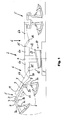
- FIG. 1 schematically shows a circular ride, on the base frame 1 of which a central structure 2 rotatable about the central axis 4 is arranged, from the upper end of which extension arms 6 extend radially outward.
- the cantilever arms 6 are divided in this embodiment and each consist of a support arm 6a rigidly connected to the central structure 2, on which (radially outward) a swivel arm 6b is pivotally articulated about the axis 14, which is tangential to the central axis 4.
- the tie rods 12 are articulated on the one hand at 15 on the swivel arms 6b, on the other hand on the eccentric device 10, namely their driving ring 28; the latter is described in more detail below.
- Structural structures in the form of satellite crosses 5 are arranged rotatably about their central axis 11 at the free ends of the swivel arms 6b.
- the electromotive drive 13 is only indicated in the form of the hub of the satellite cross 5.
- the arms 3 of the satellite cross 5 end in support pieces 7 for the pivot axes 9 to the passenger carriers 8 are rotatably attached by means of support arms 8a and hubs 8b which are in turn fastened thereon.
- the inclination of the axes 9 with respect to the main plane of the satellite cross 5, on the basis of which the pivot axes 9, as it were, enclose acute angles with the top of the arms 3, can be clearly seen in the drawing.
- Restraint bars 8c in the passenger carriers 8 serve to ensure the safety of the passengers when operating the circular shop.
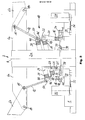
- FIGS. 2 and 3 show the eccentric device 10 in its (outermost) working position, in which the swivel arms 6b with the attached passenger carriers 8 are swiveled up and back alternately, while FIG. 3 illustrates the rest position of the eccentric device 10, in which all the passenger carriers 8 are Take a position where passengers can get on and off.
- the central building 2 has a column 2a, which is supported on a rotary ball joint 38 so as to be rotatable about the central axis 4.
- a pinion 30 meshes with the ring gear 39 of the ball slewing ring 38, which pinion can be driven by an electric motor 33 via a countershaft 31 and a belt drive 32.
- a turntable 16 is arranged concentrically to the column 2a and the central axis 4 and is rotatably mounted about the central axis 4 on a rotary ball joint 40 (independently of the column 2a).
- the fixed part of the ball slewing bearing 40 is supported as well fixed part of the ball slewing ring 38 on the base plate 1.
- An electric motor 37 can drive a pinion 34 via belts 36 and a countershaft 35, which meshes with the external toothing 42 of the ball slewing ring 40 and rotates the slewing ring 16 about the central axis 4.
- the piston rod 26 of a hydraulic cylinder 24 is mounted on the slewing ring 16 with the aid of components not of interest here, about the axis 25 tangential to the central axis 4.
- the cylinder 24 is pivotally mounted about an axis 27 parallel to the axis 25 on a further slewing ring 18.
- the turntables 14, 18 are also connected by a stand 20 which is attached diametrically to the piston rod 26 of the hydraulic cylinder 24 on the turntable 16 and at the other end a radial shoulder 44 on the turntable 18 about the axis 22 pivotally mounted.
- the axis 22 runs parallel to the superimposed axes 25 and 27, but offset by 180 ° with respect to the slewing rings 16 and 18.
- the ends of the tie rods 12 facing the central building 2 are pivotally supported by axles 50 — again tangential to the central axis 4 — axes 50.
- the other ends of the tie rods 12 are articulated with the axes 15 on the swivel arms 6b.
- the support arms 6a fastened thereon take the swivel arms 6b and also the driving ring 28 via the tie rods 12.
- This rotation of the driving ring 28 is independent of whether the slewing rings 16 and 18 also rotate or - if they do so - their speed about the central axis 4 is the same or a different one. Because the ball slewing ring 46 allows a relative rotation.
- the electric motor 37 can drive the pinion 34 and thus the slewing ring 16. If the slewing ring 16 rotates about the central axis 4, it also takes along the slewing ring 18 as a result of the connection, on the one hand, through the stand 20 and, on the other hand, through the hydraulic cylinder 24 with the piston rod 26.
- each pull rod 12 which is located just above the pivot axis 22 of the rotating ring 18, all other pull rods 12 are pulled down and accordingly pivot their pivot arms 6b, as can be seen on the left in FIGS. 1 and 2 .
- each pull rod 12 periodically passes through the two extreme positions shown in FIG. 2 and each intermediate position, which leads to the desired pivoting of the swivel arms 6b with the satellite crosses 5.
- the rotary movements generated by the electric motors 33, 37 can be superimposed on one another, specifically with an opposite direction of rotation. Because then a relatively frequent and thus rapid rocking movement of the satellite crosses 5 can be generated with relatively slow speeds. Vice versa with the same direction and the same fast drive of both rotating systems, the satellite crosses 5 would not be swung up and down even if the rotating ring 18 and the driving ring 28 assume their position shown in FIG. 2, the eccentric device 10 is therefore in the (extreme) working position. Rather, the wholly or partially raised satellite crosses 5 would maintain this relative position, as would the lowered or only slightly raised satellite cross 5 regardless of the rotation of the column 2a about the central axis 4 (and thus a corresponding rotation of the satellite crosses 5 about the central axis 4).
- the arrangement described above has the further advantage that, due to the positioning of the lifting device (hydraulic cylinder 24, piston rod 26) on the one hand and the stator 20 on the other hand, the position of the lifting device (ie the axial position of the hydraulic cylinder 24 and the piston rod 26) below the axes 50 of the tie rods 12 ) can be selected independently of the tie rod mounting.
- the axes 22 and 50 advantageously have the same distance from the central axis 4, so that the lifting movement of the turntable 18 only leads to the pivoting up (not also partially lowering) of the satellite crosses 5.
Landscapes
- Transmission Devices (AREA)
- Motorcycle And Bicycle Frame (AREA)
- Chair Legs, Seat Parts, And Backrests (AREA)
- Cage And Drive Apparatuses For Elevators (AREA)
- Walking Sticks, Umbrellas, And Fans (AREA)
- Vehicle Body Suspensions (AREA)
- Warehouses Or Storage Devices (AREA)
- Cultivation Receptacles Or Flower-Pots, Or Pots For Seedlings (AREA)
- Hydroponics (AREA)
- Catching Or Destruction (AREA)
- Vehicle Waterproofing, Decoration, And Sanitation Devices (AREA)
- Vehicle Step Arrangements And Article Storage (AREA)
- Manufacturing Optical Record Carriers (AREA)
- Golf Clubs (AREA)
- Preliminary Treatment Of Fibers (AREA)
Priority Applications (1)
| Application Number | Priority Date | Filing Date | Title |
|---|---|---|---|
| AT89112832T ATE64869T1 (de) | 1987-03-19 | 1988-03-11 | Rundfahrgeschaeft mit einem zentralbau und einer hub- und exzentereinrichtung. |
Applications Claiming Priority (2)
| Application Number | Priority Date | Filing Date | Title |
|---|---|---|---|
| DE8704120U DE8704120U1 (de) | 1987-03-19 | 1987-03-19 | Rundfahrgeschäft |
| DE8704120U | 1987-03-19 |
Related Parent Applications (1)
| Application Number | Title | Priority Date | Filing Date |
|---|---|---|---|
| EP88103851.7 Division | 1988-03-11 |
Publications (3)
| Publication Number | Publication Date |
|---|---|
| EP0341759A2 true EP0341759A2 (fr) | 1989-11-15 |
| EP0341759A3 EP0341759A3 (en) | 1989-12-27 |
| EP0341759B1 EP0341759B1 (fr) | 1991-07-03 |
Family
ID=6806056
Family Applications (2)
| Application Number | Title | Priority Date | Filing Date |
|---|---|---|---|
| EP88103851A Expired - Lifetime EP0283872B1 (fr) | 1987-03-19 | 1988-03-11 | Manège avec des gondoles tournant librement autour de pivots inclinés |
| EP89112832A Expired - Lifetime EP0341759B1 (fr) | 1987-03-19 | 1988-03-11 | Manège avec une structure centrale et un dispositif de levage et d'excentrique |
Family Applications Before (1)
| Application Number | Title | Priority Date | Filing Date |
|---|---|---|---|
| EP88103851A Expired - Lifetime EP0283872B1 (fr) | 1987-03-19 | 1988-03-11 | Manège avec des gondoles tournant librement autour de pivots inclinés |
Country Status (4)
| Country | Link |
|---|---|
| EP (2) | EP0283872B1 (fr) |
| AT (2) | ATE56628T1 (fr) |
| DE (3) | DE8704120U1 (fr) |
| ES (2) | ES2017771B3 (fr) |
Cited By (4)
| Publication number | Priority date | Publication date | Assignee | Title |
|---|---|---|---|---|
| EP0408835A1 (fr) * | 1989-07-21 | 1991-01-23 | HUSS MASCHINENFABRIK GMBH & CO. KG | Manège avec potences et bras pendulaires oscillants placés en étoile |
| WO1992007638A1 (fr) * | 1990-11-02 | 1992-05-14 | Knijpstra Konstruktie B.V. | Dispositif pour champs de foire |
| ES2310088A1 (es) * | 2006-04-26 | 2008-12-16 | Construcciones Para Ferias Y Parques De Atracciones S.A. | Galeon giratorio para atracciones de feria. |
| EP3636329A1 (fr) * | 2018-10-08 | 2020-04-15 | K.I.G. Heerenveen B.V. | Manège |
Families Citing this family (10)
| Publication number | Priority date | Publication date | Assignee | Title |
|---|---|---|---|---|
| DE8800438U1 (de) * | 1988-01-15 | 1988-11-10 | Heininger, Silvia Anna Maria, 8909 Wiesenbach | Karussell |
| IT1242900B (it) * | 1990-03-26 | 1994-05-18 | Farfabbri S R L | Giostra rotante |
| DE9203822U1 (de) * | 1992-03-21 | 1993-08-05 | Huss Maschinenfabrik GmbH & Co KG, 28207 Bremen | Rundfahrgeschäft mit einer steil aufrichtbaren Bodenstruktur |
| DE19525429C3 (de) * | 1995-07-12 | 2003-12-04 | Maurer Friedrich Soehne | Fahrzeug mit drehbarem Oberwagen |
| DE29611422U1 (de) * | 1996-07-01 | 1997-10-30 | Huss Maschinenfabrik GmbH & Co KG, 28207 Bremen | Rundfahrgeschäft |
| DE19724272C2 (de) * | 1997-06-09 | 2001-11-15 | Maurer Friedrich Soehne | Fahrzeug für Fahrgeschäfte |
| WO2003028834A1 (fr) * | 2001-09-26 | 2003-04-10 | Far Fabbri Srl | Manege |
| NL1025364C2 (nl) * | 2004-01-30 | 2006-10-24 | Kig Heerenveen Bv | Kermisattractie. |
| EP3020458B1 (fr) | 2014-11-17 | 2018-10-31 | Antonio Zamperla S.p.A. | Dispositif de divertissement avec structure rotative basculante |
| CN109395401B (zh) * | 2018-12-13 | 2024-05-17 | 郑州市奇乐迪游乐设备有限公司 | 一种转盘类游乐设备 |
Family Cites Families (9)
| Publication number | Priority date | Publication date | Assignee | Title |
|---|---|---|---|---|
| BE477378A (fr) * | ||||
| DE675596C (de) * | 1936-04-15 | 1939-05-12 | Karl Weigand | Mittels Kegelrad antreibbares Karussell |
| DE1113402B (de) * | 1959-02-13 | 1961-08-31 | Kaspar Klaus | Einrichtung zum Verschwenken einer hoehenverstellbaren Auslegertragvorrichtung fuer ein Karussell |
| US3219344A (en) * | 1963-08-07 | 1965-11-23 | Allan H Tober | Amusement ride |
| DE1980612U (de) * | 1967-11-17 | 1968-03-07 | Schwarzkopf Stahl Fahrzeugbau | Karussell. |
| DE1956873B2 (de) * | 1968-11-13 | 1971-09-30 | Vorrichtung zum volumetrischen abmessen eines koernigen materials | |
| CH556187A (de) * | 1972-11-14 | 1974-11-29 | Intamin Ag | Vorrichtung zur durchfuehrung von belustigungs-rundfahrten. |
| GB2082924B (en) * | 1980-09-03 | 1984-12-12 | Turnagain Ltd | Rotatable passenger-carrying apparatus |
| DE3150432C2 (de) * | 1981-12-19 | 1985-07-25 | K.H. Huss KG, 2800 Bremen | Rundfahrgeschäft mit Bodenscheibe |
-
1987
- 1987-03-19 DE DE8704120U patent/DE8704120U1/de not_active Expired
-
1988
- 1988-03-11 DE DE8989112832T patent/DE3863545D1/de not_active Expired - Fee Related
- 1988-03-11 ES ES88103851T patent/ES2017771B3/es not_active Expired - Lifetime
- 1988-03-11 AT AT88103851T patent/ATE56628T1/de not_active IP Right Cessation
- 1988-03-11 ES ES89112832T patent/ES2023024B3/es not_active Expired - Lifetime
- 1988-03-11 EP EP88103851A patent/EP0283872B1/fr not_active Expired - Lifetime
- 1988-03-11 DE DE8888103851T patent/DE3860626D1/de not_active Expired - Fee Related
- 1988-03-11 AT AT89112832T patent/ATE64869T1/de not_active IP Right Cessation
- 1988-03-11 EP EP89112832A patent/EP0341759B1/fr not_active Expired - Lifetime
Cited By (7)
| Publication number | Priority date | Publication date | Assignee | Title |
|---|---|---|---|---|
| EP0408835A1 (fr) * | 1989-07-21 | 1991-01-23 | HUSS MASCHINENFABRIK GMBH & CO. KG | Manège avec potences et bras pendulaires oscillants placés en étoile |
| WO1992007638A1 (fr) * | 1990-11-02 | 1992-05-14 | Knijpstra Konstruktie B.V. | Dispositif pour champs de foire |
| US5395290A (en) * | 1990-11-02 | 1995-03-07 | Knijpstra Konstruktie B.V. | Fairground device |
| ES2310088A1 (es) * | 2006-04-26 | 2008-12-16 | Construcciones Para Ferias Y Parques De Atracciones S.A. | Galeon giratorio para atracciones de feria. |
| ES2310088B1 (es) * | 2006-04-26 | 2009-11-06 | Construcciones Para Ferias Y Parques De Atracciones S.A. | Galeon giratorio para atracciones de feria. |
| EP3636329A1 (fr) * | 2018-10-08 | 2020-04-15 | K.I.G. Heerenveen B.V. | Manège |
| US10967282B2 (en) | 2018-10-08 | 2021-04-06 | K.I.G. Heerenveen B.V. | Attraction for entertainment rides |
Also Published As
| Publication number | Publication date |
|---|---|
| ES2023024B3 (es) | 1991-12-16 |
| EP0341759B1 (fr) | 1991-07-03 |
| DE8704120U1 (de) | 1988-07-28 |
| EP0283872B1 (fr) | 1990-09-19 |
| ATE64869T1 (de) | 1991-07-15 |
| EP0283872A2 (fr) | 1988-09-28 |
| ES2017771B3 (es) | 1991-03-01 |
| ATE56628T1 (de) | 1990-10-15 |
| EP0283872A3 (en) | 1988-12-21 |
| EP0341759A3 (en) | 1989-12-27 |
| DE3860626D1 (de) | 1990-10-25 |
| DE3863545D1 (de) | 1991-08-08 |
Similar Documents
| Publication | Publication Date | Title |
|---|---|---|
| EP0341759B1 (fr) | Manège avec une structure centrale et un dispositif de levage et d'excentrique | |
| DE19742260C2 (de) | Karussell | |
| EP0140238B1 (fr) | Appareil d'exploitation mobile, pour divertissements publics | |
| EP0146096B1 (fr) | Table tournante et élévatrice | |
| EP0036200B1 (fr) | Balançoire | |
| EP0474260B1 (fr) | Balançoire bouclant la boucle avec nacelle pour passagers, suspendue à la cardan | |
| DE1113402B (de) | Einrichtung zum Verschwenken einer hoehenverstellbaren Auslegertragvorrichtung fuer ein Karussell | |
| DE2227446C3 (de) | Doppelkran | |
| EP0408835B1 (fr) | Manège avec potences et bras pendulaires oscillants placés en étoile | |
| DE9104204U1 (de) | Rundfahrgeschäft | |
| DE3113247A1 (de) | Windkraftanlage | |
| DE3938318C2 (de) | Vergnügungsvorrichtung, insbesondere Schaukel | |
| EP4368268A1 (fr) | Appareil de divertissement pour les marchés de transport ou similaires | |
| DE2513297B2 (de) | Kreiselheuwerbungsmaschine mit einem dreipunktrahmen zum wahlweisen front- oder heckseitigen anbau an eine zugmaschine | |
| EP0562428B1 (fr) | Manège avec une construction de fond raidement relevable | |
| DE8800438U1 (de) | Karussell | |
| DE29606585U1 (de) | Karussel | |
| DE2202355C3 (de) | Karussell mit mehreren Auslegern und von diesen getragenen, drehbaren Sitzkorbträgern | |
| DE2952032A1 (de) | Rundfahrgeschaeft | |
| EP0656222B1 (fr) | Dispositif d'exploitation mobile avec au moins une nacelle pour passagers suspendue pendulante | |
| WO2003041826A1 (fr) | Manege | |
| DE865280C (de) | Windkraftmaschine | |
| DE2206339C3 (de) | Karussell | |
| DE2041102C2 (de) | Heuwerbungsmaschine | |
| DE9209202U1 (de) | Rundfahrgeschäft |
Legal Events
| Date | Code | Title | Description |
|---|---|---|---|
| PUAI | Public reference made under article 153(3) epc to a published international application that has entered the european phase |
Free format text: ORIGINAL CODE: 0009012 |
|
| PUAL | Search report despatched |
Free format text: ORIGINAL CODE: 0009013 |
|
| AC | Divisional application: reference to earlier application |
Ref document number: 283872 Country of ref document: EP |
|
| AK | Designated contracting states |
Kind code of ref document: A2 Designated state(s): AT BE CH DE ES FR GB IT LI NL |
|
| AK | Designated contracting states |
Kind code of ref document: A3 Designated state(s): AT BE CH DE ES FR GB IT LI NL |
|
| 17P | Request for examination filed |
Effective date: 19900109 |
|
| 17Q | First examination report despatched |
Effective date: 19900829 |
|
| GRAA | (expected) grant |
Free format text: ORIGINAL CODE: 0009210 |
|
| AC | Divisional application: reference to earlier application |
Ref document number: 283872 Country of ref document: EP |
|
| AK | Designated contracting states |
Kind code of ref document: B1 Designated state(s): AT BE CH DE ES FR GB IT LI NL |
|
| REF | Corresponds to: |
Ref document number: 64869 Country of ref document: AT Date of ref document: 19910715 Kind code of ref document: T |
|
| ITF | It: translation for a ep patent filed | ||
| GBT | Gb: translation of ep patent filed (gb section 77(6)(a)/1977) | ||
| REF | Corresponds to: |
Ref document number: 3863545 Country of ref document: DE Date of ref document: 19910808 |
|
| ET | Fr: translation filed | ||
| PLBE | No opposition filed within time limit |
Free format text: ORIGINAL CODE: 0009261 |
|
| STAA | Information on the status of an ep patent application or granted ep patent |
Free format text: STATUS: NO OPPOSITION FILED WITHIN TIME LIMIT |
|
| 26N | No opposition filed | ||
| PGFP | Annual fee paid to national office [announced via postgrant information from national office to epo] |
Ref country code: GB Payment date: 20010911 Year of fee payment: 14 Ref country code: ES Payment date: 20010911 Year of fee payment: 14 |
|
| PGFP | Annual fee paid to national office [announced via postgrant information from national office to epo] |
Ref country code: FR Payment date: 20010912 Year of fee payment: 14 |
|
| PGFP | Annual fee paid to national office [announced via postgrant information from national office to epo] |
Ref country code: AT Payment date: 20010913 Year of fee payment: 14 |
|
| PGFP | Annual fee paid to national office [announced via postgrant information from national office to epo] |
Ref country code: BE Payment date: 20010925 Year of fee payment: 14 |
|
| PGFP | Annual fee paid to national office [announced via postgrant information from national office to epo] |
Ref country code: CH Payment date: 20010927 Year of fee payment: 14 |
|
| PGFP | Annual fee paid to national office [announced via postgrant information from national office to epo] |
Ref country code: NL Payment date: 20010930 Year of fee payment: 14 |
|
| PGFP | Annual fee paid to national office [announced via postgrant information from national office to epo] |
Ref country code: DE Payment date: 20011228 Year of fee payment: 14 |
|
| REG | Reference to a national code |
Ref country code: GB Ref legal event code: IF02 |
|
| PG25 | Lapsed in a contracting state [announced via postgrant information from national office to epo] |
Ref country code: GB Free format text: LAPSE BECAUSE OF NON-PAYMENT OF DUE FEES Effective date: 20020311 Ref country code: AT Free format text: LAPSE BECAUSE OF NON-PAYMENT OF DUE FEES Effective date: 20020311 |
|
| PG25 | Lapsed in a contracting state [announced via postgrant information from national office to epo] |
Ref country code: ES Free format text: LAPSE BECAUSE OF NON-PAYMENT OF DUE FEES Effective date: 20020312 |
|
| PG25 | Lapsed in a contracting state [announced via postgrant information from national office to epo] |
Ref country code: LI Free format text: LAPSE BECAUSE OF NON-PAYMENT OF DUE FEES Effective date: 20020331 Ref country code: CH Free format text: LAPSE BECAUSE OF NON-PAYMENT OF DUE FEES Effective date: 20020331 Ref country code: BE Free format text: LAPSE BECAUSE OF NON-PAYMENT OF DUE FEES Effective date: 20020331 |
|
| BERE | Be: lapsed |
Owner name: *HUSS MASCHINENFABRIK G.M.B.H. & CO. K.G. Effective date: 20020331 |
|
| PG25 | Lapsed in a contracting state [announced via postgrant information from national office to epo] |
Ref country code: NL Free format text: LAPSE BECAUSE OF NON-PAYMENT OF DUE FEES Effective date: 20021001 Ref country code: DE Free format text: LAPSE BECAUSE OF NON-PAYMENT OF DUE FEES Effective date: 20021001 |
|
| GBPC | Gb: european patent ceased through non-payment of renewal fee |
Effective date: 20020311 |
|
| REG | Reference to a national code |
Ref country code: CH Ref legal event code: PL |
|
| PG25 | Lapsed in a contracting state [announced via postgrant information from national office to epo] |
Ref country code: FR Free format text: LAPSE BECAUSE OF NON-PAYMENT OF DUE FEES Effective date: 20021129 |
|
| NLV4 | Nl: lapsed or anulled due to non-payment of the annual fee |
Effective date: 20021001 |
|
| REG | Reference to a national code |
Ref country code: FR Ref legal event code: ST |
|
| REG | Reference to a national code |
Ref country code: ES Ref legal event code: FD2A Effective date: 20030410 |
|
| PG25 | Lapsed in a contracting state [announced via postgrant information from national office to epo] |
Ref country code: IT Free format text: LAPSE BECAUSE OF NON-PAYMENT OF DUE FEES;WARNING: LAPSES OF ITALIAN PATENTS WITH EFFECTIVE DATE BEFORE 2007 MAY HAVE OCCURRED AT ANY TIME BEFORE 2007. THE CORRECT EFFECTIVE DATE MAY BE DIFFERENT FROM THE ONE RECORDED. Effective date: 20050311 |