EP0342103A1 - Bandwerkzeugmodul, geeignet, allein oder mit anderen Modulen zu arbeiten - Google Patents
Bandwerkzeugmodul, geeignet, allein oder mit anderen Modulen zu arbeiten Download PDFInfo
- Publication number
- EP0342103A1 EP0342103A1 EP19890401257 EP89401257A EP0342103A1 EP 0342103 A1 EP0342103 A1 EP 0342103A1 EP 19890401257 EP19890401257 EP 19890401257 EP 89401257 A EP89401257 A EP 89401257A EP 0342103 A1 EP0342103 A1 EP 0342103A1
- Authority
- EP
- European Patent Office
- Prior art keywords
- wafer
- frame
- holder
- assembly
- plate
- Prior art date
- Legal status (The legal status is an assumption and is not a legal conclusion. Google has not performed a legal analysis and makes no representation as to the accuracy of the status listed.)
- Withdrawn
Links
Images


Classifications
-
- B—PERFORMING OPERATIONS; TRANSPORTING
- B21—MECHANICAL METAL-WORKING WITHOUT ESSENTIALLY REMOVING MATERIAL; PUNCHING METAL
- B21D—WORKING OR PROCESSING OF SHEET METAL OR METAL TUBES, RODS OR PROFILES WITHOUT ESSENTIALLY REMOVING MATERIAL; PUNCHING METAL
- B21D37/00—Tools as parts of machines covered by this subclass
- B21D37/02—Die constructions enabling assembly of the die parts in different ways
Definitions
- the subject of the present invention is a frame for a tool working on the strip capable of being used both in the form of a unitary module and in a multimodular assembly.
- the subject of the present invention is a frame for a tool working at the strip, for the performance of manufacturing operations, such as cutting, bending, stamping, etc., of parts from a strip or blank.
- raw material said frame comprising, as constituent elements, a punch holder and a die holder, of generally rectangular configuration, mounted facing each other and each offering standardized receiving means adapted to receive sets forming tools, called " wafers ", which wafers are also standardized, so as to be interchangeable, and respectively consist of punches (" wafer / punches ") and dies (" wafer / dies ”) in correspondence, a pair of wafer / punches and wafer / dies forming a work station, the dies holder further having a cutout for the evacuation of raw material waste and / or finished parts, the strip of raw material circulating along the axis lo ngitudinal of the frame.
- the punch holder and the die holder are, of course, adapted to be mounted respectively on the upper and lower jaws of a press.
- the tools punches and dies
- the discharge cutout is substantially rectangular, its longitudinal axis merging with the longitudinal axis of the frame.
- This orientation which is determined by construction, cannot be changed. It will be noted that by “substantially rectangular” is meant a shape that is longer than it is wide, for example a square extended on two opposite sides by portions of a circle.
- the blank holder tends to bend at the level of the unused station or stations. To avoid this sag, it may be necessary to mount, at the unused stations, wedge-shaped pancakes.
- the substantially rectangular cutout retains its orientation relative to the direction of movement of the strip, in order to provide, over the length of frame, the maximum surface area at the fall of the waste and / or finished parts, while keeping enough material across the width of the frame so as not to affect the rigidity of the latter. It is indeed the matrices which undergo the greatest effort.
- the object of the invention is to remedy these drawbacks, which is achieved in that it provides a frame in which: - the evacuation cutout is substantially rectangular and it is created in a square plate, called "orientation plate", interposed between the wafer / dies and the die holder, the receiving means of the wafer / dies are provided on said orientation plate, and - Indexing and assembly means are provided for joining said orientation plate to the die holder in a location that is rigorously centered with respect to the entire frame, but in two possible orientations, at 90 ° one of the other.
- the wafer / punches can be mounted and dismounted from the punch holder in a direction transverse to the direction of circulation of the strip of raw material, rails depending on said punch holder being adapted to support and guide said wafer during assembly and disassembly.
- orientation plate a square plate, called "orientation plate”
- the means for receiving the wafer / punches are provided on said orientation plate
- Indexing and assembly means are provided for joining said orientation plate to the punch holder in a location that is rigorously centered with respect to the entire frame, but in two possible orientations, at 90 ° one of the other.
- the frame will further comprise, as a constitutive element, a blank holder also offering standardized receiving means adapted to receive a tool assembly called "wafer / blank holder” also standardized and interchangeable, said wafer / blank holder having cutouts for the passage of the punches of the wafer / punches, rails depending on said blank holder and being adapted to support and guide said wafer / blank holder during its assembly and disassembly in a transverse direction to the direction of circulation of the raw material strip.
- a blank holder also offering standardized receiving means adapted to receive a tool assembly called "wafer / blank holder” also standardized and interchangeable, said wafer / blank holder having cutouts for the passage of the punches of the wafer / punches, rails depending on said blank holder and being adapted to support and guide said wafer / blank holder during its assembly and disassembly in a transverse direction to the direction of circulation of the raw material strip.
- orientation plate a square plate, called "orientation plate”
- the receiving means of the wafer / blank holder are provided on said orientation plate
- - Indexing and assembly means are provided for joining said orientation plate to the blank holder in a location that is rigorously centered with respect to the entire frame, but in two possible orientations, at 90 ° one of the other.
- the blank holder has a square opening with a side at least equal to the length of a substantially rectangular cutout provided in its orientation plate, as is the case for the die holder.
- the indexing means of the orientation plate consist of four pins matching four holes made in the vicinity of each of the angles of the square which it determines, and four holes of the element constituting a frame which receives said plate, said holes being all rigorously centered with respect to the whole of the frame.
- the orientation plate comprises, on its receiving face of the wafer, horizontal in the normal position of use, a pair of grooves arranged on either side of the wafer according to a first horizontal axis of symmetry and a pair of grooves arranged on either side of the wafer according to a second horizontal axis of symmetry perpendicular to the first, said pair of grooves being adapted to receive the end of a pair of pins indexing crossing said wafer and each groove of said pair of grooves being adapted to receive the lower end of the vertical branch of a T-flange, while the remaining part of said T-flange is capable of being accommodated in a cross milling provided on the side wall of the wafer, the vertical branch of each of said cross milling being crossed by a vertical plane of symmetry of the wafer, perpendicular to the vertical plane of symmetry passing through said pins , said T flanges being adapted to slide, with a vertical clearance, in said grooves and to be locked in engagement with the
- the frame comprises, in a manner known per se, on the one hand columns on which slide the punch holder and possibly the blank holder and, on the other hand, actuating cylinders of said punch holder and / or said hold-down.
- the punch holder, the blank holder and the die holder of the frame according to the invention have on their longitudinal edges two symmetrical cutouts with respect to the diagonals of their generally rectangular configuration, which cutouts spare, in said longitudinal edges, only the space necessary for the location of said columns and said jacks.
- the multimodular assembly comprises a common upper sole and a common lower sole to which are joined, respectively, the juxtaposition of punch holders and the juxtaposition of die holders.
- the frame of the module according to the invention comprises, in a manner known per se, a punch holder 1, a blank holder 2 and a door -matrices 3, the punch holder 1 and the blank holder 2 being capable of sliding on columns 4.
- the punch holder and the die holder are adapted to each receive a "pancake "circular or square on which are distributed, respectively, punches and dies corresponding to each other, according to a distribution which is a function of the part to be manufactured and the step of advance chosen for the strip of raw material from which the parts are made.
- Such a cake is represented in 5 (cake circular) and in 5 ′ (square wafer) in Figure 1 and the tools (pairs of punches and dies) are shown schematically in 6a and 7a respectively.
- the blank holder 2 is likewise adapted to receive a wafer having holes adapted to allow the passage of the punches of the punch holder 1.
- the module according to the invention designated in its together by M, is oriented so that the strip of raw material flows in the direction of the arrows B.
- the wafer 5 or 5 ′ is, in turn, respectively introduced and extracted from the module according to arrows 0.
- the shape of the module M is roughly rectangular and, when this module is used in a unitary state, the strip circulates along the length of the module and the wafers are put in place and extracted perpendicular to this length.
- the strip flows in a direction B parallel to the width of each unit module (but of course according to the length of the multimodular unit) and the wafers are put in place and extracted from each of the modules in a direction 01, 02, 03 perpendicular to the width of each module.
- each of the modules M1, M2 and M3 are respectively joined to a common upper junction sole 8 and to a common lower junction sole 9. This meeting takes place at the cutouts 29 and positioning pins, the longitudinal axis of each of the workstations then being rigorously placed at identical inter-axes, their transverse axis passing rigorously through the longitudinal axis of the multimodular assembly to form a perfect alignment of the different modules.
- the roughly rectangular shape of the elements constituting the frame of the module has two longitudinal cutouts 10 allowing the modules to nest together, with a concomitant reduction in the length of the multimodular unit (FIG. 3).
- the invention provides for mounting the wafers on the punch holder, on the blank holder and on the die holder, not directly as is known according to the prior art, but with the interposition of a plate square orientation.
- This plate is designated by the reference 11 in Figure 1, respectively 11a, 11b and 11c in Figures 6 and 7, and omitted in Figure 3 so as not to overload the drawing.
- each of the plates 11a, 11b and 11c is exactly centered, respectively on the punch holder 1, the blank holder 2 and the die holder 3, by means of indexing pins 12 strictly positioned.
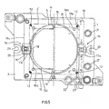
- the square plate 11c of the die holder 3 has a substantially rectangular cut 13c (in the case of the embodiment shown, a cut roughly in the shape of a "football" field), cut 13c which, in the configuration of FIG. 5, has the same general orientation as the module. In other words, when the module is used in the unitary state, the cut 13c provided for the fall of the waste of material or the fall of the finished parts, has its length parallel to the length of the module.
- the pins 12 are removed, the plate 11c is unscrewed from the die holder 3, it is turned 90 ° and it is replaced, in this new orientation, on the die holder with a rigorously centered positioning using the pins 12. It follows that, in the multimodular configuration, the cut 13c has its length parallel to the width of each of the modules, and parallel to the length of the multimodular unit.
- the plates 11a and 11b, respectively, of the punch holder 1 and of the die holder 2 are re-orientable in the same way.
- the die holder 3 has a square opening 30c, the side of which is slightly longer than the length of the discharge cutout 13c.
- a similar square opening 30b is provided in the blank holder 2.
- FIG. 5 we also see, at 31, a clearance provided in the blank holder.
- the module according to the invention can use both circular wafers 5 and square wafers 5 ′.
- Square wafers have the advantage of offering a larger tool distribution surface for the same size.
- said square plates For mounting the pancakes 5 or 5 ′ in the square plates 11a, llb, 11c, said square plates comprise, as can be seen better in FIG. 8, a pair of grooves 14 adapted to receive pins 15 perfectly centered with respect to the center of the square plate.
- the pins 15 ensure correct relative positioning, in a first direction.
- each of these devices comprises a T-flange 17a, 17b, 17c movable in translation in a groove 27, vis-à-vis which it can also have a slight vertical sliding movement.
- This T flange 17a, 17b, 17c which is likely to come into engagement with a cross milling 18 provided in the wafer 5 or 5 ′, has a light 19 allowing the above-mentioned translational movement.
- a screw 20 ensures the vertical locking of the flange 17 in the bottom of the groove 27.
- Figure 5 shows in 21 and 21 ′ the position occupied by the jacks when the module is used in the unitary state. There are two other locations at 22 and 22 ′ which will be used when the module is mounted in a multimodular unit. Depending on the use made of the module, the user therefore mounts the cylinders at 21, 21 ′ or 22, 22 ′.
- FIGS. 6 and 7, are referred the references previously used. The corresponding parts will not be described again.
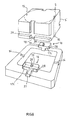
- Figure 6 shows that the frame according to the invention is equipped with rails 27a, 27b for sliding in place the wafer equipping the punch holder 1 and the wafer equipping the blank holder 2.
- These rails 27a and 27b are respectively fixed to the plates 11a and 11b orientation so that by properly orienting said plates, it is possible to keep the front loading of wafers that are working on a unitary module or on a mutlimodular assembly.
- 17a and 17b the centering flange, clamping and lardonnage of these wafers.
- the reference 17c designates, as before, the flange provided for the wafer equipping the die holder.
- FIG. 7 shows one of the jacks 41 used for the operation of the blank holder 2, and the parts which depend thereon, and one of the jacks 26 used for the pressure of the greenhouse. - blank 2.
- the construction of the frame according to the invention is more economical than that of the previously known frame because, the basic module being always the same, its manufacture causes the series effect which lowers the manufacturing costs.
Landscapes
- Engineering & Computer Science (AREA)
- Mechanical Engineering (AREA)
- Packaging Frangible Articles (AREA)
- Container, Conveyance, Adherence, Positioning, Of Wafer (AREA)
Applications Claiming Priority (2)
| Application Number | Priority Date | Filing Date | Title |
|---|---|---|---|
| FR8806225A FR2630939B1 (fr) | 1988-05-09 | 1988-05-09 | Module d'outil travaillant a la bande, adapte a travailler a l'etat unitaire ou en ensemble multimodulaire |
| FR8806225 | 1988-05-09 |
Publications (1)
| Publication Number | Publication Date |
|---|---|
| EP0342103A1 true EP0342103A1 (de) | 1989-11-15 |
Family
ID=9366130
Family Applications (1)
| Application Number | Title | Priority Date | Filing Date |
|---|---|---|---|
| EP19890401257 Withdrawn EP0342103A1 (de) | 1988-05-09 | 1989-05-03 | Bandwerkzeugmodul, geeignet, allein oder mit anderen Modulen zu arbeiten |
Country Status (2)
| Country | Link |
|---|---|
| EP (1) | EP0342103A1 (de) |
| FR (1) | FR2630939B1 (de) |
Cited By (3)
| Publication number | Priority date | Publication date | Assignee | Title |
|---|---|---|---|---|
| US6532783B2 (en) * | 1997-07-11 | 2003-03-18 | Fico B.V. | Clamping device, tool and method of mounting tools |
| CN112517720A (zh) * | 2020-12-19 | 2021-03-19 | 河南江州电气有限公司 | 一种机构箱防水顶盖一次成型装置 |
| CN117380053A (zh) * | 2023-12-11 | 2024-01-12 | 艾斯普瑞(广州)食品有限公司 | 一种婴儿米饼的加工装置及方法 |
Citations (2)
| Publication number | Priority date | Publication date | Assignee | Title |
|---|---|---|---|---|
| EP0100271A1 (de) * | 1982-07-21 | 1984-02-08 | Michel Lefils | Vereinfachte Konstruktion von Werkzeugen, zum Erweitern der Einsatzmöglichkeit von Bandwerkzeugen bei der Herstellung von metallischen Produkten in kleiner und mittelgrosser Serie |
| FR2596700A1 (fr) * | 1986-04-08 | 1987-10-09 | Esswein Sa | Outil de presse a modules |
-
1988
- 1988-05-09 FR FR8806225A patent/FR2630939B1/fr not_active Expired - Lifetime
-
1989
- 1989-05-03 EP EP19890401257 patent/EP0342103A1/de not_active Withdrawn
Patent Citations (2)
| Publication number | Priority date | Publication date | Assignee | Title |
|---|---|---|---|---|
| EP0100271A1 (de) * | 1982-07-21 | 1984-02-08 | Michel Lefils | Vereinfachte Konstruktion von Werkzeugen, zum Erweitern der Einsatzmöglichkeit von Bandwerkzeugen bei der Herstellung von metallischen Produkten in kleiner und mittelgrosser Serie |
| FR2596700A1 (fr) * | 1986-04-08 | 1987-10-09 | Esswein Sa | Outil de presse a modules |
Cited By (4)
| Publication number | Priority date | Publication date | Assignee | Title |
|---|---|---|---|---|
| US6532783B2 (en) * | 1997-07-11 | 2003-03-18 | Fico B.V. | Clamping device, tool and method of mounting tools |
| CN112517720A (zh) * | 2020-12-19 | 2021-03-19 | 河南江州电气有限公司 | 一种机构箱防水顶盖一次成型装置 |
| CN117380053A (zh) * | 2023-12-11 | 2024-01-12 | 艾斯普瑞(广州)食品有限公司 | 一种婴儿米饼的加工装置及方法 |
| CN117380053B (zh) * | 2023-12-11 | 2024-03-01 | 艾斯普瑞(广州)食品有限公司 | 一种婴儿米饼的加工装置及方法 |
Also Published As
| Publication number | Publication date |
|---|---|
| FR2630939A1 (fr) | 1989-11-10 |
| FR2630939B1 (fr) | 1991-04-05 |
Similar Documents
| Publication | Publication Date | Title |
|---|---|---|
| EP0201395A1 (de) | Einrichtung zum Zusammenbau, insbesondere für Karosseriebearbeitungsstrassen | |
| EP0100271B1 (de) | Vereinfachte Konstruktion von Werkzeugen, zum Erweitern der Einsatzmöglichkeit von Bandwerkzeugen bei der Herstellung von metallischen Produkten in kleiner und mittelgrosser Serie | |
| FR2677287A1 (fr) | Appareil de changement d'outils pour une poinconneuse a tourelle. | |
| EP0513624A1 (de) | Vorrichtung zum Stapeln und Stapelwenden für eine sogenannte Druckslottermaschine zur Herstellung von Verpackungsbehältern | |
| CH634154A5 (fr) | Procede de soudage de plusieurs fibres optiques bout a bout par nappes et dispositif de soudage selon ce procede. | |
| FR2727895A1 (fr) | Procede pour la realisation d'une lentille optique en matiere synthetique polymerisable et appareillage correspondant | |
| EP0342103A1 (de) | Bandwerkzeugmodul, geeignet, allein oder mit anderen Modulen zu arbeiten | |
| CH690027A5 (fr) | Outil supérieur mobile pour la séparation des poses d'une feuille travaillée par une presse de fabrication d'emballages. | |
| WO1992002059A1 (fr) | Procedes et dispositifs pour sertir mecaniquement une piece de connexion sur un fil | |
| WO1997018907A1 (fr) | Outillage reglable de pliage de toles | |
| CH660993A5 (fr) | Procede d'usinage d'une piece et machine-outil modulaire pour la mise en oeuvre de ce procede. | |
| WO2001045114A1 (fr) | Dispositif et procede de montage d'une grille-entretoise d'un assemblage de combustible pour un reacteur nucleaire | |
| EP0452312A1 (de) | Werkzeugmaschine, aus bauteilen zusammengesetzt und mit mindestens einer bearbeitungseinheit | |
| FR2799680A1 (fr) | Machine automatique d'assemblage de cadres | |
| EP0904614B1 (de) | Krimpwerkzeug für serienfertigung von metallische kabelschuhe und werkzeugkassette | |
| EP0932474B1 (de) | Rotationsvorrichtung zum wechseln von mit einer werkzeugmaschine zu bearbeitenden werkstücken | |
| EP0468855B1 (de) | Werkzeugschnellwechselanordnung für eine Presse | |
| CH689972A5 (fr) | Dispositif pour la manutention et le réglage des outils d'une presse à découper. | |
| EP0031759A2 (de) | Universalnageltisch zum Zusammensetzen und Nageln von Transportpaletten | |
| FR2784537A1 (fr) | Procede de montage d'une installation electrique ou electronique de puissance et echangeur de chaleur pour composants electriques ou electroniques de puissance | |
| EP0156825A1 (de) | Maschine zum schrittweisen fördern von wechselarbeitsplatten | |
| FR2472960A1 (fr) | Aleseuse-finisseuse multibroches bilaterales | |
| EP2414244B1 (de) | Anlage und verfahren zum verpacken von komponenten in form von streifen | |
| CH497945A (fr) | Bloc à colonnes | |
| FR2705105A1 (fr) | Dispositif de dressage de nipples d'anodes. |
Legal Events
| Date | Code | Title | Description |
|---|---|---|---|
| PUAI | Public reference made under article 153(3) epc to a published international application that has entered the european phase |
Free format text: ORIGINAL CODE: 0009012 |
|
| AK | Designated contracting states |
Kind code of ref document: A1 Designated state(s): AT BE CH DE ES FR GB IT LI LU NL SE |
|
| 17P | Request for examination filed |
Effective date: 19900511 |
|
| 17Q | First examination report despatched |
Effective date: 19920521 |
|
| RAP1 | Party data changed (applicant data changed or rights of an application transferred) |
Owner name: LEFILS, REINE Owner name: LEFILS, LAURENT Owner name: LEFILS, HELENE |
|
| RIN1 | Information on inventor provided before grant (corrected) |
Inventor name: LEFILS, MICHEL |
|
| STAA | Information on the status of an ep patent application or granted ep patent |
Free format text: STATUS: THE APPLICATION IS DEEMED TO BE WITHDRAWN |
|
| 18D | Application deemed to be withdrawn |
Effective date: 19930112 |