EP0342387B1 - Dispositif de suspension pour charges mobiles, notamment pour canalisations et d'objets similaires - Google Patents
Dispositif de suspension pour charges mobiles, notamment pour canalisations et d'objets similaires Download PDFInfo
- Publication number
- EP0342387B1 EP0342387B1 EP89107304A EP89107304A EP0342387B1 EP 0342387 B1 EP0342387 B1 EP 0342387B1 EP 89107304 A EP89107304 A EP 89107304A EP 89107304 A EP89107304 A EP 89107304A EP 0342387 B1 EP0342387 B1 EP 0342387B1
- Authority
- EP
- European Patent Office
- Prior art keywords
- load
- suspension
- spring device
- constant
- hydraulic
- Prior art date
- Legal status (The legal status is an assumption and is not a legal conclusion. Google has not performed a legal analysis and makes no representation as to the accuracy of the status listed.)
- Expired - Lifetime
Links
- 239000000725 suspension Substances 0.000 claims description 29
- 230000006835 compression Effects 0.000 claims description 3
- 238000007906 compression Methods 0.000 claims description 3
- 230000001105 regulatory effect Effects 0.000 claims description 3
- 238000010586 diagram Methods 0.000 description 3
- 238000000034 method Methods 0.000 description 3
- 230000001186 cumulative effect Effects 0.000 description 1
- 230000006735 deficit Effects 0.000 description 1
- 230000000694 effects Effects 0.000 description 1
- 238000009413 insulation Methods 0.000 description 1
- 238000004519 manufacturing process Methods 0.000 description 1
- 239000007787 solid Substances 0.000 description 1
- 230000003068 static effect Effects 0.000 description 1
- 230000001960 triggered effect Effects 0.000 description 1
- XLYOFNOQVPJJNP-UHFFFAOYSA-N water Substances O XLYOFNOQVPJJNP-UHFFFAOYSA-N 0.000 description 1
Images

Classifications
-
- F—MECHANICAL ENGINEERING; LIGHTING; HEATING; WEAPONS; BLASTING
- F16—ENGINEERING ELEMENTS AND UNITS; GENERAL MEASURES FOR PRODUCING AND MAINTAINING EFFECTIVE FUNCTIONING OF MACHINES OR INSTALLATIONS; THERMAL INSULATION IN GENERAL
- F16L—PIPES; JOINTS OR FITTINGS FOR PIPES; SUPPORTS FOR PIPES, CABLES OR PROTECTIVE TUBING; MEANS FOR THERMAL INSULATION IN GENERAL
- F16L3/00—Supports for pipes, cables or protective tubing, e.g. hangers, holders, clamps, cleats, clips, brackets
- F16L3/16—Supports for pipes, cables or protective tubing, e.g. hangers, holders, clamps, cleats, clips, brackets with special provision allowing movement of the pipe
- F16L3/20—Supports for pipes, cables or protective tubing, e.g. hangers, holders, clamps, cleats, clips, brackets with special provision allowing movement of the pipe allowing movement in transverse direction
- F16L3/215—Supports for pipes, cables or protective tubing, e.g. hangers, holders, clamps, cleats, clips, brackets with special provision allowing movement of the pipe allowing movement in transverse direction the movement being hydraulically or electrically controlled
- F16L3/217—Supports for pipes, cables or protective tubing, e.g. hangers, holders, clamps, cleats, clips, brackets with special provision allowing movement of the pipe allowing movement in transverse direction the movement being hydraulically or electrically controlled hydraulically
-
- F—MECHANICAL ENGINEERING; LIGHTING; HEATING; WEAPONS; BLASTING
- F16—ENGINEERING ELEMENTS AND UNITS; GENERAL MEASURES FOR PRODUCING AND MAINTAINING EFFECTIVE FUNCTIONING OF MACHINES OR INSTALLATIONS; THERMAL INSULATION IN GENERAL
- F16L—PIPES; JOINTS OR FITTINGS FOR PIPES; SUPPORTS FOR PIPES, CABLES OR PROTECTIVE TUBING; MEANS FOR THERMAL INSULATION IN GENERAL
- F16L3/00—Supports for pipes, cables or protective tubing, e.g. hangers, holders, clamps, cleats, clips, brackets
- F16L3/16—Supports for pipes, cables or protective tubing, e.g. hangers, holders, clamps, cleats, clips, brackets with special provision allowing movement of the pipe
- F16L3/20—Supports for pipes, cables or protective tubing, e.g. hangers, holders, clamps, cleats, clips, brackets with special provision allowing movement of the pipe allowing movement in transverse direction
- F16L3/205—Supports for pipes, cables or protective tubing, e.g. hangers, holders, clamps, cleats, clips, brackets with special provision allowing movement of the pipe allowing movement in transverse direction having supporting springs
- F16L3/2056—Supports for pipes, cables or protective tubing, e.g. hangers, holders, clamps, cleats, clips, brackets with special provision allowing movement of the pipe allowing movement in transverse direction having supporting springs the axis of at least one spring being oblique or perpendicular to the direction of the movement of the pipe
Definitions
- the invention relates to a suspension device for moving loads, in particular pipelines and the like, and a constant tensile force, in which an equilibrium between a solid body and the like and the moving load can be adjusted to maintain a substantially constant load or supporting force, and in which a regulating and control unit is provided while maintaining the equilibrium to the initial value, wherein a spring device can be assigned to the adjustable member (constant hanger).
- Deviations can occur, for example, due to influences in pipe statics that are not always ideally ascertainable, practical deviations from the theoretical load distribution, wall thickness tolerances of the pipes, if these are not weighed separately and the weight differences are taken into account, insulation weights that cannot be precisely measured in advance, mechanical friction and manufacturing tolerances at the Hanging device and also due to the fatigue of the springs in constant hangers. Cumulative deviations in long-legged, so-called soft piping systems have a particularly unfavorable effect. Movements of the vertical strand can be partially or completely hindered in the expansion leg even with relatively small deviations. In addition to the damage mentioned, dangerous water hammer, for example due to a wrong slope, can also occur.
- a carrying or supporting device for maintaining a substantially constant carrying or supporting force on an object subject to movement, a force-responsive, acting on the balance and by a deviation of the carrying or Provide support force from the initially predetermined value operated control or switching device for returning the load or support force to substantially its initial value.
- the adjustable member is relieved of at least part of the weight of the load, with a spring or spring device being connected in parallel with the adjustable member.
- the spring should be parallel to the adjustable link and connected to the load via the force-responsive link.
- the device for keeping the balance is relatively cumbersome and expensive.
- the device for tare the balance is located above the cylinder in which the spring is located.
- the invention relates specifically to a suspension device for moving loads, in particular Pipelines and the like according to EP-A 0188 654, namely on a suspension device with a constant tensile force, with an additional suspension to compensate for the changing thrust and pressure force of the suspension between the suspension part and the load-bearing part arranged to hold the load Main suspension is provided.
- the additional suspension acts as a compression suspension via a roller with a curve part.
- the further spring device as the servo-hydraulic of the load-bearing part is accommodated in the load pipe cooperating with the additional suspension, the cylinder of which is articulated on the holder of the housing of the device and the piston rod is fastened to the load pipe.
- the arrangement is such that the cylinder of the servo-hydraulic system is connected to a hydraulic control unit by hydraulic lines on both sides of the piston.
- the hydraulic control unit is connected to the control device by control lines.
- the hydraulic auxiliary device is completely integrated in the other design and configuration. You can retrofit the known suspension device at any time without making any changes to the known device.
- the external dimensions of the suspension device can be maintained and there is no need for more space. There are no components outside the housing.
- the space required for the additional device is extremely small or an existing space is used cheaply and highly effectively. A susceptibility to failure is also very low.
- the servo-hydraulic unit according to the invention has nothing to do with weight relief, rather it has Servo-hydraulics in the invention, the function of improving the passively reacting suspension device in such a way that the reaction force of the suspension device is supplemented by the actively acting device in such a way that the load differences are compensated in a controlled manner. This is done in a structurally simple manner.
- a servo-hydraulic control device which, in the event of a deviation from the constant hanger position, which corresponds to the load to be taken up by the constant hanger, switches on the servo-hydraulic system and switches off the servo-hydraulic unit when the target value is reached.
- the servo device merely represents a correction device which monitors the correct function of the constant hanger and only intervenes if the constant hanger is prevented by any interference sources from being able to move to the previously calculated correct position for which the constant hanger is designed.
- the senor can interact with a part attached to the load tube.
- the other sensor can be attached to the part to be removed by the constant hanger and e.g. consist of a temperature sensor.
- the values of the sensors are compared with each other, whereupon the servo hydraulic unit is activated accordingly.
- Fig. 1 shows an embodiment of the suspension device according to the invention as a constant hanger with a servo-hydraulic unit in longitudinal section and in the diagram.
- Fig. 2 shows a side view - partly in section - of the constant hanger of Figure 1 schematically.
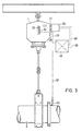
- Fig. 3 shows in the diagram the overall arrangement of the constant hanger with servo-hydraulic and transducer in view.
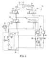
- Fig. 4 schematically illustrates the hydraulic system in the diagram.
- the suspension device 1 as a constant hanger for shifting loads, such as pipes 2 and the like, has a housing 3 as a suspension part, in which a load-bearing part 4 is provided, which is under the action of a main suspension 5 receiving the load. This is supported against a lower abutment 6, which by means of screw bolts 7 to the lower crossmember 8 of the housing 3 is arranged adjustable. With its other end, the main suspension 5 is supported on a head piece 9, which serves as an abutment, to which a sleeve 10 is fastened, which projects beyond the lower abutment 6.
- the sleeve 10 as the load tube is closed by a plate 11 in which a pendulum part 12 for receiving the load to be carried, for example a holder, a pipeline and the like, is mounted.
- the head piece 9 carries rollers 14 and 15 projecting on both sides on the axles 13.
- the additional springs 17 and 18 to compensate for a changing tensile and compressive force of the main suspension 5 from a central position for keeping the holding force constant consist of compression springs which are arranged between the abutments 19 and 20 on the one hand and 21 and 22 on the other and in the transverse direction to the main axis the main suspension 5 run.
- pivot levers 24 and 25 are arranged, which are designed as cam arms and have curve parts 26 and 27 directly, which with the rollers 14 and 15 of the head piece 9 of the main suspension 5 cooperate.
- the swivel levers 24, 25 also take over the function of cams and are under the action of the additional suspension 17 and 18.
- the swivel levers as cam arms can be mounted standing or hanging. In the zero position, the additional spring and the cam parts are expediently in the upper or in the middle region of the main suspension 5. With 28 and 29, adjusting elements are designated, which are advantageously designed as adjusting screws.
- the pivot levers 24, 25 are mounted on axes 30, which are held by the side walls of the housing 3.
- the head piece 9 with the load tube 10 is guided in the longitudinal slots 34 and 35 by means of the cross bolts 32, 33.
- the upper abutment plate 36 is provided with upstanding plate parts 37, 38 to which the guide bolts 32, 33 are fastened.
- 39 is a holder for attaching the constant hanger or the housing 3 to a stationary frame or the like. designated.
- a hydraulically operating auxiliary device 41 (servo unit) is arranged integrated in the constant hanger. It is intended to cause an additional force of a predetermined size in both directions of movement to the main force.
- the servo hydraulic unit 41 has a cylinder 42 which is connected to the holder 39 by a joint 43. In the cylinder 42 there is a piston 44 with a piston rod 45 which is fixedly connected to a transverse wall 46 arranged in the load tube 10. Hydraulic lines 47 and 48 lead to a hydraulic control unit 50 on both sides of the piston 44.
- the hydraulic control unit 50 has a pressure generating device 51, motor 52, pump 53, tank 54, pressure relief valve 55, pressure switch 56 and pressure accumulator 57.
- Four three-way valves 59 are arranged between the servo-hydraulics 41 and the pressure generating device 51 to 57, each two in lines 47 and 48. In the lines, pressure relief valves 59 and a number of check valves 60 are also provided.
- a measured value transducer 62 is arranged on the outside of the housing 3 of the constant hanger 1 for the servo hydraulic unit, which cooperates with a part attached to the load tube 10.
- a guide pin 32 or 33 is advantageously used, which indicates the movements of the load tube 10 to the outside.
- This sensor is a position sensor.
- Another transducer 63 is on the part to be removed between the constant hanger, e.g. the pipe 2, attached. It advantageously consists of a temperature sensor. The temperature of the pipeline is measured with the temperature sensor. This temperature is the measure for the target value during the warm / cold movement of the constant hanger.
- a control line 65 leads from the measured value sensor 62 for determining the travel position of the constant hanger to a control device 66 and from the measured value sensor 63, for example a resistance thermometer, a control line 67 also leads to the control device 66, which works electronically or is designed as a process computer.
- Control lines 68 and 69 lead from the control device 66 to the hydraulic unit 50, by means of which the additional force is generated and transmitted to the load tube of the constant hanger by means of the piston-cylinder unit.
- the hydraulics are designed so that at least 10%, but better an additional force in both directions up to 50% of the nominal load of the constant hanger can be applied.
- the temperature is measured by means of the transducer 63, which is attached to the outer wall of the component to be removed, for example the pipeline. This value is converted into the required travel position of the constant hanger by means of the control device. This position represents the target position of the piston rod position.
- the other transducer 62 which directly picks up the position on the constant hanger, represents the actual position of the constant hanger. If there is a difference between the target and actual values, the hydraulic unit is switched on and by appropriate Control of the solenoid valves 59 (upward or downward movement of the piston rod) is brought into the desired position.
- the servo-hydraulic system is only activated when a difference between the actual and the target position of the constant hanger is determined by means of the sensor.
- a constant comparison is carried out between the target value based on the measured temperature and the actual value based on the measured path on the trailer, expediently in an electronic manner. If there is a difference between the setpoint and actual value, the hydraulic unit attached to the constant hanger is switched and the hydraulic cylinder installed in the load tube of the constant hanger is activated via the solenoid valves. By actuating the hydraulic cylinder, the constant hanger is set so that the setpoint and actual value are at the same level or almost the same level.
- the hydraulic unit is switched off and the pressure in the hydraulic cylinder is reduced, so that the load is again only carried by the constant hanger.
- the regulation takes place expediently until the desired compensation assumes a value that is within an adjustable tolerance range. In the event that the control process cannot be carried out successfully within a certain time, for example 2 minutes, the control process must be aborted and an alarm signal triggered.
Landscapes
- Engineering & Computer Science (AREA)
- General Engineering & Computer Science (AREA)
- Mechanical Engineering (AREA)
- Supports For Pipes And Cables (AREA)
- Vehicle Body Suspensions (AREA)
Claims (2)
- Dispositif de suspension (1) exerçant une force de traction qui reste constante, pour des charges qui se déplacent, en particulier pour des canalisations (2) ou similaires, dans lequel un équilibre entre un support fixe ou similaire (3) et la charge mobile (4) est réglable afin de maintenir une force portante ou d'appui pratiquement constante, et dans lequel un groupe de réglage et de commande (41, 50) est prévu pour le maintien de l'équilibre à la valeur initiale, un dispositif à ressort étant associé à l'organe réglable, caractérisé en ce que, dans le cas d'un dispositif de suspension (1) dans lequel, en association avec un système à ressort (5) qui absorbe la charge et qui est disposé entre la partie de suspension (3) et la partie (4) portant la charge, un système à ressort supplémentaire (17, 18) est prévu pour compenser la force de traction et de compression variable du système à ressort principal (5) et coopère avec lui, en tant que ressort de compression, par l'intermédiaire d'un galet (14, 15) et d'un élément à came (26, 27), un autre dispositif à ressort est logé dans le tube de charge (10) qui coopère avec le système à ressort supplémentaire (17, 18), cet autre dispositif se présentant sous forme de servo-commande hydraulique (41) de la partie (4) portant la charge, dont le cylindre (42) est articulé (en 43) sur l'élément de fixation (39) du boîtier (3) du dispositif et dont la tige de piston est fixée au tube de charge (10).
- Dispositif de suspension selon la revendication 1, caractérisé en ce que le cylindre (42) de la servo-commande hydraulique (41) est raccordé à un groupe de commande hydraulique (50) par des conduites hydrauliques (47, 48) des deux côtés du piston (44), et en ce que le groupe de commande hydraulique (50) est relié au dispositif de réglage (66) par des lignes de commande (68, 69).
Applications Claiming Priority (2)
| Application Number | Priority Date | Filing Date | Title |
|---|---|---|---|
| DE3816673 | 1988-05-17 | ||
| DE3816673A DE3816673A1 (de) | 1988-05-17 | 1988-05-17 | Aufhaengevorrichtung fuer sich verschiebende lasten, insbesondere rohrleitungen u. dgl. |
Publications (2)
| Publication Number | Publication Date |
|---|---|
| EP0342387A1 EP0342387A1 (fr) | 1989-11-23 |
| EP0342387B1 true EP0342387B1 (fr) | 1993-02-10 |
Family
ID=6354483
Family Applications (1)
| Application Number | Title | Priority Date | Filing Date |
|---|---|---|---|
| EP89107304A Expired - Lifetime EP0342387B1 (fr) | 1988-05-17 | 1989-04-22 | Dispositif de suspension pour charges mobiles, notamment pour canalisations et d'objets similaires |
Country Status (4)
| Country | Link |
|---|---|
| US (1) | US5018700A (fr) |
| EP (1) | EP0342387B1 (fr) |
| JP (1) | JPH076586B2 (fr) |
| DE (2) | DE3816673A1 (fr) |
Families Citing this family (32)
| Publication number | Priority date | Publication date | Assignee | Title |
|---|---|---|---|---|
| JP3247960B2 (ja) * | 1992-09-07 | 2002-01-21 | 株式会社リコー | 画像形成装置及びトナー像除去装置 |
| US5588511A (en) * | 1995-05-15 | 1996-12-31 | Sargent & Lundy | Seismic pipe restraint and method for using the same |
| US5687655A (en) * | 1996-04-18 | 1997-11-18 | Hon Industries Inc. | Adjustable height load bearing support structure |
| US6736419B2 (en) | 2001-11-06 | 2004-05-18 | Meritor Light Vehicle Technology, Llc | Vehicle suspension system using viscous tension dampers |
| DE102005045736B4 (de) * | 2005-09-23 | 2008-12-11 | Lisega Ag | Konstantträger |
| DE102006062195B3 (de) * | 2006-12-22 | 2008-04-30 | Lisega Ag | Konstantträger |
| US8011856B2 (en) * | 2007-08-10 | 2011-09-06 | Mendel Nock | Constant thrust restraint of pipeline walking |
| WO2009039659A1 (fr) * | 2007-09-26 | 2009-04-02 | Robarts Research Institute | Ensemble contrepoids |
| US20090152782A1 (en) * | 2007-12-17 | 2009-06-18 | Honeywell International, Inc. | User interface with controllable dual spring rate return to null cantilever springs |
| EP2402636B1 (fr) | 2009-02-27 | 2014-04-09 | Juntas Y Compensadores, S.L. | Dispositif de support de conduites industrielles |
| CN101706018B (zh) * | 2009-11-27 | 2012-05-23 | 高永峰 | 自补偿式恒力弹簧支吊架 |
| CN101725767B (zh) * | 2010-01-15 | 2011-08-10 | 高永峰 | 同轴式恒力弹簧支吊架 |
| US8689646B2 (en) * | 2011-01-26 | 2014-04-08 | Cynthia Kriesmer Carr | Sealed, slim-line constant force, generation unit |
| CN103133781B (zh) * | 2013-03-11 | 2014-12-24 | 江苏大秦电气有限公司 | 可显示载荷与位移恒力弹簧吊架 |
| EP3042373B1 (fr) * | 2013-09-03 | 2023-06-07 | Intune Technologies, LLC | Dispositif à tension constante |
| US9791093B2 (en) * | 2013-10-11 | 2017-10-17 | Canon Finetech Nisca Inc. | Load support mechanism |
| CN103574170B (zh) * | 2013-11-12 | 2015-09-09 | 成都科盛石油科技有限公司 | 一种可调式管道支架 |
| CN104089097A (zh) * | 2014-06-30 | 2014-10-08 | 江苏大力城电气有限公司 | 一种加强的恒力弹簧支吊架 |
| CN104315279B (zh) * | 2014-09-26 | 2016-08-10 | 中国工程物理研究院总体工程研究所 | 新型自适应液膜密封旋转接头 |
| US20160104465A1 (en) | 2014-10-13 | 2016-04-14 | Intune Technologies, Llc | Low-friction bridge for stringed instrument |
| US9792886B2 (en) * | 2015-01-22 | 2017-10-17 | Intune Technologies, Llc | String tensioner for stringed instrument |
| CN105042182B (zh) * | 2015-09-08 | 2018-08-10 | 山东佳能科技股份有限公司 | 管道沉降保护器 |
| DE102015218851A1 (de) * | 2015-09-30 | 2017-03-30 | Siemens Aktiengesellschaft | Federaggregat, Federspeicher und Aktor |
| WO2017105303A1 (fr) * | 2015-12-16 | 2017-06-22 | Saab Ab | Agencement d'absorption de chocs conçu pour supporter un choc d'impact |
| CN107860662B (zh) * | 2017-10-26 | 2020-04-14 | 中国船舶重工集团公司第七0四研究所 | 一种大型深水主被动联合波浪补偿装置陆上试验方法 |
| CN109030230B (zh) * | 2018-10-18 | 2023-09-15 | 西安热工研究院有限公司 | 一种恒力弹簧支吊架调试及载荷检测装置 |
| CN110220047B (zh) * | 2019-05-30 | 2021-02-26 | 西安航天动力试验技术研究所 | 一种大口径低温管路快速调节支撑装置 |
| CN110410443B (zh) * | 2019-08-05 | 2020-08-14 | 北京航空航天大学 | 一种零刚度冲击隔离装置 |
| CN111550610A (zh) * | 2020-06-09 | 2020-08-18 | 西安热工研究院有限公司 | 一种载荷逆向变化的复合型弹性支吊装置 |
| DE102020116261A1 (de) | 2020-06-19 | 2021-12-23 | Lisega SE | Positionsanzeigevorrichtung für ein Tragelement |
| CN111963043A (zh) * | 2020-07-29 | 2020-11-20 | 乐屋(广东)高新科技有限公司 | 一种管状电机限位装置 |
| CN118959764B (zh) * | 2024-10-15 | 2025-03-18 | 南京中特化工动力设备有限公司 | 一种多向位移减振弹簧支吊架 |
Family Cites Families (6)
| Publication number | Priority date | Publication date | Assignee | Title |
|---|---|---|---|---|
| DE863734C (de) * | 1939-08-12 | 1953-01-19 | Gen Spring Corp | Trag- oder Stuetzvorrichtung |
| US3112909A (en) * | 1961-12-26 | 1963-12-03 | Bergen Pipesupport Corp | Support apparatus for piping and the like |
| US3606233A (en) * | 1968-04-22 | 1971-09-20 | Bolt Beranek & Newman | Vibration isolation system |
| DE2306674A1 (de) * | 1973-02-10 | 1974-08-15 | Lisega Gmbh | Aufhaengevorrichtung fuer sich verschiebende lasten, vornehmlich rohrleitungen |
| DE7617092U1 (de) * | 1976-05-28 | 1977-08-18 | Lisega Kraftwerkstechnik Gmbh & Co Kg, 2148 Zeven | Aufhängevorrichtung für sich verschiebende Lasten, insbesondere Rohrleitungen u.dgl |
| DE3501853A1 (de) * | 1985-01-22 | 1986-07-24 | Lisega Kraftwerkstechnik GmbH, 2730 Zeven | Aufhaengevorrichtung fuer sich verschiebende lasten, insbesondere rohrleitungen u.dgl. |
-
1988
- 1988-05-17 DE DE3816673A patent/DE3816673A1/de not_active Withdrawn
-
1989
- 1989-04-22 DE DE8989107304T patent/DE58903492D1/de not_active Expired - Lifetime
- 1989-04-22 EP EP89107304A patent/EP0342387B1/fr not_active Expired - Lifetime
- 1989-05-15 US US07/351,621 patent/US5018700A/en not_active Expired - Lifetime
- 1989-05-17 JP JP1121667A patent/JPH076586B2/ja not_active Expired - Fee Related
Also Published As
| Publication number | Publication date |
|---|---|
| DE58903492D1 (de) | 1993-03-25 |
| JPH076586B2 (ja) | 1995-01-30 |
| US5018700A (en) | 1991-05-28 |
| DE3816673A1 (de) | 1989-11-30 |
| EP0342387A1 (fr) | 1989-11-23 |
| JPH0211987A (ja) | 1990-01-17 |
Similar Documents
| Publication | Publication Date | Title |
|---|---|---|
| EP0342387B1 (fr) | Dispositif de suspension pour charges mobiles, notamment pour canalisations et d'objets similaires | |
| EP0591304B1 (fr) | Commande et regulation electroniques de l'equilibre d'engins de levage | |
| DE102005045736B4 (de) | Konstantträger | |
| DE102010006169B4 (de) | Doppelscheibenschar mit Tiefenführungsrolle | |
| EP2106513A1 (fr) | Support constant | |
| DE2029814A1 (fr) | ||
| DD298029A5 (de) | Vorrichtung und verfahren zur einachsigen mechanischen werkstoffpruefung | |
| DE10214755B4 (de) | Waage mit einem Trägerelement zur Ankopplung einer Waagschale an eine Wägezelle | |
| EP2615433B1 (fr) | Dispositif et procédé d'ajustement de l'erreur de charge angulaire d'une direction parallèle | |
| EP2860501A1 (fr) | Cellule de pesée dotée d'un dispositif de correction d'erreurs de charge excentriques et procédé de correction d'erreurs de charge excentriques | |
| DE102009053665A1 (de) | Anhängevorrichtung | |
| WO2007107139A1 (fr) | Dispositif de suspension ou de soutien pour des charges qui se deplacent dans la direction verticale et en particulier pour des conduits tubulaires et similaires | |
| DE2745473A1 (de) | Aufhaengevorrichtung einer warmgehenden rohrleitung | |
| DE1555063A1 (de) | Einrichtung zum Regeln der Scheinwerfereinstellung eines Fahrzeugs | |
| EP2434264A1 (fr) | Dispositif de transmission d'énergie avec un poids de calibrage pouvant être couplé | |
| DE8806433U1 (de) | Aufhängevorrichtung für sich verschiebende Lasten, insbesondere Rohrleitungen u. dgl. | |
| DE3517688A1 (de) | Haltevorrichtung fuer eine rohrleitung | |
| EP1293765A2 (fr) | Procédé de calibrage d'un frein à puissance d'un banc d'essai de moteurs à combustion interne | |
| DE3430125A1 (de) | Vorrichtung zur steuerung einer schwenkbar an einem fahrzeug befestigten maschinenbaugruppe | |
| DE1959878B2 (de) | Aufhaengevorrichtung, insbesondere fuer rohrleitungen | |
| DE69030307T2 (de) | Verfahren zum Positionieren eines Bauteils, das mit einer Platte verbunden ist oder einen Teil derselben bildet, sowie Vorrichtung zum Durchführen des Verfahren, und nach diesem Verfahren hergestellte Platte | |
| EP0489230A2 (fr) | Mât de levage, en particulier pour chariots-élévateurs | |
| DE2623928A1 (de) | Aufhaengevorrichtung fuer sich verschiebende lasten, insbesondere rohrleitungen u.dgl. | |
| EP4344930A1 (fr) | Collecteur de courant | |
| DE1458240C3 (de) | Einer Stranggießkokille nachgeschaltete Strangtransporteinrichtung |
Legal Events
| Date | Code | Title | Description |
|---|---|---|---|
| PUAI | Public reference made under article 153(3) epc to a published international application that has entered the european phase |
Free format text: ORIGINAL CODE: 0009012 |
|
| AK | Designated contracting states |
Kind code of ref document: A1 Designated state(s): DE FR GB GR IT |
|
| 17P | Request for examination filed |
Effective date: 19891202 |
|
| 17Q | First examination report despatched |
Effective date: 19901002 |
|
| GRAA | (expected) grant |
Free format text: ORIGINAL CODE: 0009210 |
|
| AK | Designated contracting states |
Kind code of ref document: B1 Designated state(s): DE FR GB GR IT |
|
| PG25 | Lapsed in a contracting state [announced via postgrant information from national office to epo] |
Ref country code: GR Free format text: LAPSE BECAUSE OF FAILURE TO SUBMIT A TRANSLATION OF THE DESCRIPTION OR TO PAY THE FEE WITHIN THE PRESCRIBED TIME-LIMIT Effective date: 19930210 |
|
| REF | Corresponds to: |
Ref document number: 58903492 Country of ref document: DE Date of ref document: 19930325 |
|
| ITF | It: translation for a ep patent filed | ||
| ET | Fr: translation filed | ||
| GBT | Gb: translation of ep patent filed (gb section 77(6)(a)/1977) |
Effective date: 19930517 |
|
| PLBE | No opposition filed within time limit |
Free format text: ORIGINAL CODE: 0009261 |
|
| STAA | Information on the status of an ep patent application or granted ep patent |
Free format text: STATUS: NO OPPOSITION FILED WITHIN TIME LIMIT |
|
| 26N | No opposition filed | ||
| REG | Reference to a national code |
Ref country code: GB Ref legal event code: IF02 |
|
| PGFP | Annual fee paid to national office [announced via postgrant information from national office to epo] |
Ref country code: IT Payment date: 20080428 Year of fee payment: 20 |
|
| PGFP | Annual fee paid to national office [announced via postgrant information from national office to epo] |
Ref country code: DE Payment date: 20080624 Year of fee payment: 20 |
|
| PGFP | Annual fee paid to national office [announced via postgrant information from national office to epo] |
Ref country code: FR Payment date: 20080418 Year of fee payment: 20 |
|
| PGFP | Annual fee paid to national office [announced via postgrant information from national office to epo] |
Ref country code: GB Payment date: 20080423 Year of fee payment: 20 |
|
| REG | Reference to a national code |
Ref country code: GB Ref legal event code: PE20 Expiry date: 20090421 |
|
| PG25 | Lapsed in a contracting state [announced via postgrant information from national office to epo] |
Ref country code: GB Free format text: LAPSE BECAUSE OF EXPIRATION OF PROTECTION Effective date: 20090421 |