EP0344117A2 - Procédé et dispositif pour laminer des rainures dans des queues d'outils - Google Patents
Procédé et dispositif pour laminer des rainures dans des queues d'outils Download PDFInfo
- Publication number
- EP0344117A2 EP0344117A2 EP89810372A EP89810372A EP0344117A2 EP 0344117 A2 EP0344117 A2 EP 0344117A2 EP 89810372 A EP89810372 A EP 89810372A EP 89810372 A EP89810372 A EP 89810372A EP 0344117 A2 EP0344117 A2 EP 0344117A2
- Authority
- EP
- European Patent Office
- Prior art keywords
- grooves
- insertion end
- segments
- axial direction
- rolled
- Prior art date
- Legal status (The legal status is an assumption and is not a legal conclusion. Google has not performed a legal analysis and makes no representation as to the accuracy of the status listed.)
- Granted
Links
- 238000000034 method Methods 0.000 title claims description 16
- 238000005096 rolling process Methods 0.000 title abstract description 14
- 238000003780 insertion Methods 0.000 claims abstract description 44
- 230000037431 insertion Effects 0.000 claims abstract description 44
- 238000004519 manufacturing process Methods 0.000 claims abstract description 8
- 238000005553 drilling Methods 0.000 claims abstract description 3
- 239000000463 material Substances 0.000 description 7
- 230000009467 reduction Effects 0.000 description 3
- 239000000835 fiber Substances 0.000 description 2
- 239000012530 fluid Substances 0.000 description 2
- 238000003754 machining Methods 0.000 description 2
- 230000007704 transition Effects 0.000 description 2
- 230000015572 biosynthetic process Effects 0.000 description 1
- 238000004049 embossing Methods 0.000 description 1
- 230000002349 favourable effect Effects 0.000 description 1
- 230000002028 premature Effects 0.000 description 1
- 238000007493 shaping process Methods 0.000 description 1
- 239000007787 solid Substances 0.000 description 1
- 239000004575 stone Substances 0.000 description 1
Images

Classifications
-
- B—PERFORMING OPERATIONS; TRANSPORTING
- B21—MECHANICAL METAL-WORKING WITHOUT ESSENTIALLY REMOVING MATERIAL; PUNCHING METAL
- B21K—MAKING FORGED OR PRESSED METAL PRODUCTS, e.g. HORSE-SHOES, RIVETS, BOLTS OR WHEELS
- B21K5/00—Making tools or tool parts, e.g. pliers
- B21K5/02—Making tools or tool parts, e.g. pliers drilling-tools or other for making or working on holes
- B21K5/10—Forming drill-bit shanks
-
- B—PERFORMING OPERATIONS; TRANSPORTING
- B21—MECHANICAL METAL-WORKING WITHOUT ESSENTIALLY REMOVING MATERIAL; PUNCHING METAL
- B21H—MAKING PARTICULAR METAL OBJECTS BY ROLLING, e.g. SCREWS, WHEELS, RINGS, BARRELS, BALLS
- B21H7/00—Making articles not provided for in the preceding groups, e.g. agricultural tools, dinner forks, knives, spoons
- B21H7/18—Making articles not provided for in the preceding groups, e.g. agricultural tools, dinner forks, knives, spoons grooved pins; Rolling grooves, e.g. oil grooves, in articles
- B21H7/187—Rolling helical or rectilinear grooves
-
- B—PERFORMING OPERATIONS; TRANSPORTING
- B21—MECHANICAL METAL-WORKING WITHOUT ESSENTIALLY REMOVING MATERIAL; PUNCHING METAL
- B21K—MAKING FORGED OR PRESSED METAL PRODUCTS, e.g. HORSE-SHOES, RIVETS, BOLTS OR WHEELS
- B21K1/00—Making machine elements
- B21K1/44—Making machine elements bolts, studs, or the like
- B21K1/54—Making machine elements bolts, studs, or the like with grooves or notches
-
- B—PERFORMING OPERATIONS; TRANSPORTING
- B21—MECHANICAL METAL-WORKING WITHOUT ESSENTIALLY REMOVING MATERIAL; PUNCHING METAL
- B21H—MAKING PARTICULAR METAL OBJECTS BY ROLLING, e.g. SCREWS, WHEELS, RINGS, BARRELS, BALLS
- B21H7/00—Making articles not provided for in the preceding groups, e.g. agricultural tools, dinner forks, knives, spoons
- B21H7/18—Making articles not provided for in the preceding groups, e.g. agricultural tools, dinner forks, knives, spoons grooved pins; Rolling grooves, e.g. oil grooves, in articles
Definitions
- the invention relates to a forming process, in particular for the production of drilling and chiseling tools, with a grooved insertion end.
- Tools such as those produced by means of a forming process of the aforementioned type are known, for example, from DE-PS 2 551 125 and are used in particular for stone processing.
- the tools are inserted into a receptacle of a drive device, this receptacle having fixed or radially disengageable locking elements which engage in a form-fitting manner in the grooves of the insertion end of the tools. Torque can be transmitted to the tool via these locking elements and the tool can be prevented from being ejected from the receptacle.
- the form-fitting holder in the receptacle grooves of the insertion end can be produced in different ways.
- This machining production has the disadvantages known per se, such as a high expenditure of time and unfavorable influencing of the material by interrupting the fiber course.
- the further known embossing method according to DE-OS 3 015 893 was also not able to completely eliminate the disadvantages, particularly with regard to expenditure of time.
- due to the high forces occurring in this forming process a relatively large expenditure on equipment is required.
- the invention has for its object to provide a forming process that enables simple and efficient production of the grooves in the insertion ends of tools.
- this is achieved in that the grooves are rolled into the insertion end by means of segments that roll in the axial direction at the insertion end.
- the grooves are continuously produced during the rolling of the segments, which on the one hand requires smaller forming forces and on the other hand enables the material to flow better.
- This flow of the material results in a favorable fiber orientation of the material in the area of the insertion end.
- the rolling of the grooves can be done from the free end of the insertion end or from the opposite end, ie directly to the solid.
- the grooves are expediently rolled to the full depth in one pass. This rolling of the grooves to the full depth is made possible in particular by the continuous shaping of the material and the lower power requirement compared to a pure stamping process. Rolling the grooves in one pass enables efficient production and a high surface quality in the area of the longitudinal grooves.
- the grooves can have a longitudinal extent extending in the longitudinal direction or in the circumferential direction of the insertion end.
- a device for carrying out the method according to the invention is advantageously characterized in that the segments are arranged so as to be pivotable about an axis which is substantially perpendicular to the axial direction of the insertion end.
- the segments When swiveling the segments around to the axial direction of the insertion end of the axis, which is essentially vertical, the segments roll in the axial direction at the insertion end.
- the relative movement between the segments and the insertion end can be brought about by axially displacing the axis of the segments or by a feed movement of the insertion end.
- the segments are expediently arranged on a lever which is rotatably mounted about an axis which is essentially perpendicular to the axial direction of the insertion end.
- the segments can be releasably connected to the lever and can therefore be easily replaced.
- the lever is preferably designed with two arms with an actuating arm protruding from the segment.
- a working cylinder is advantageously provided for rotating the lever.
- the working cylinder can be operated for example by means of compressed air or expediently by means of a hydraulic fluid. Since relatively high forces are necessary with a relatively short path, hydraulically operated cylinders are particularly suitable as working cylinders, which also enable good synchronization of several cylinders to be actuated simultaneously.
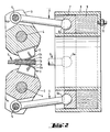
- the device shown in FIGS. 1 to 4 for producing an insertion end 1 has segments 2 which are arranged on a lever 3.
- the lever 3 is rotatably mounted about an axis 4 which is substantially perpendicular to the axial direction of the insertion end 1.
- the levers 3 have two arms and are connected to a push rod 6 at the end opposite the segments 2 by means of bolts 5.
- the push rod 6 is connected via a ball head 6a to an annular piston 7 which can be displaced in a working cylinder 8 in the axial direction of the insertion end 1.
- the ring piston 7 is displaced by means of a hydraulic fluid 9, which is supplied to the working cylinder 8 via a connecting piece 10.
- the insertion end 1 is fed between the segments 2. Due to the symmetrical arrangement of the segments 2, the insertion end 1 is centered at the same time.
- the annular piston 7 is now moved into the end position shown in FIG. 2.
- the segments 2 connected to the levers 3 roll in the axial direction at the insertion end 1 and roll grooves 1a into the surface of the insertion end 1.
- the levers 3 are rotated about the axis 4 by the annular piston 7 via the push rod 6.
- the insertion end 1 is released and the levers 3 can be rotated back into the starting position shown in FIG. 1 by the annular piston 7.
- the device is in turn ready for the production of the grooves 1a at a further insertion end 1.
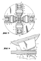
- a total of four segments 2 connected with levers 3 are arranged over the circumference of the insertion end 1.
- the levers 3 are connected to consoles 11 via the axes 4.
- the brackets 11 are attached to a face plate 12, not shown in FIGS. 1 and 2. Instead of four brackets 11, however, two, three or six brackets 11 can also be arranged on the face plate 12.
- the insertion end 1 is surrounded by the segments 2 over the entire circumference. This ensures that a precise cross section of the insertion end 1 is achieved when rolling the grooves 1a.
- the grooves 1a on the groove base are provided with a profile 1b which has stop surfaces 1c which act essentially in the axial direction.
- the profiling 1b is rolled into the surface of the insertion end 1 simultaneously with the grooves 1a by the segments 2 arranged on the lever 3.
- the segments 2 are provided with a counter-profile 2a corresponding to the profile 1b.
- the profiling 1b prevents an excessive change in length of the insertion end when rolling the grooves 1a and thereby enables the formation of an angular profile of the insertion end 1. A cross-sectional change resulting from the change in length of the insertion end 1 is thereby avoided.
Landscapes
- Mechanical Engineering (AREA)
- Engineering & Computer Science (AREA)
- Life Sciences & Earth Sciences (AREA)
- Agronomy & Crop Science (AREA)
- Forging (AREA)
- Metal Rolling (AREA)
- Milling Processes (AREA)
- Processing Of Terminals (AREA)
- Electrical Discharge Machining, Electrochemical Machining, And Combined Machining (AREA)
- Reduction Rolling/Reduction Stand/Operation Of Reduction Machine (AREA)
- Nonmetallic Welding Materials (AREA)
- Blast Furnaces (AREA)
- Polishing Bodies And Polishing Tools (AREA)
- Milling, Broaching, Filing, Reaming, And Others (AREA)
- Grinding And Polishing Of Tertiary Curved Surfaces And Surfaces With Complex Shapes (AREA)
- Perforating, Stamping-Out Or Severing By Means Other Than Cutting (AREA)
Priority Applications (1)
| Application Number | Priority Date | Filing Date | Title |
|---|---|---|---|
| AT89810372T ATE98537T1 (de) | 1988-05-25 | 1989-05-19 | Verfahren und vorrichtung zum walzen von nuten in einsteckenden von werkzeugen. |
Applications Claiming Priority (2)
| Application Number | Priority Date | Filing Date | Title |
|---|---|---|---|
| DE3817680 | 1988-05-25 | ||
| DE3817680A DE3817680A1 (de) | 1988-05-25 | 1988-05-25 | Umformungsverfahren fuer werkzeuge |
Publications (3)
| Publication Number | Publication Date |
|---|---|
| EP0344117A2 true EP0344117A2 (fr) | 1989-11-29 |
| EP0344117A3 EP0344117A3 (en) | 1990-12-27 |
| EP0344117B1 EP0344117B1 (fr) | 1993-12-15 |
Family
ID=6355057
Family Applications (1)
| Application Number | Title | Priority Date | Filing Date |
|---|---|---|---|
| EP89810372A Expired - Lifetime EP0344117B1 (fr) | 1988-05-25 | 1989-05-19 | Procédé et dispositif pour laminer des rainures dans des queues d'outils |
Country Status (8)
| Country | Link |
|---|---|
| US (1) | US4941339A (fr) |
| EP (1) | EP0344117B1 (fr) |
| JP (1) | JP2551996B2 (fr) |
| AT (1) | ATE98537T1 (fr) |
| CA (1) | CA1327133C (fr) |
| DE (2) | DE3817680A1 (fr) |
| DK (1) | DK170363B1 (fr) |
| FI (1) | FI95358C (fr) |
Cited By (4)
| Publication number | Priority date | Publication date | Assignee | Title |
|---|---|---|---|---|
| EP0467493A1 (fr) * | 1990-07-12 | 1992-01-22 | MANNESMANN Aktiengesellschaft | Appareil de forgeage oscillant |
| US6528079B2 (en) | 1996-06-04 | 2003-03-04 | Bayer Aktiengesellschaft | Shaped bodies which release agrochemical active substances |
| CH714772A1 (de) * | 2018-11-15 | 2019-09-13 | Grob Ernst Fa | Vorrichtung und Verfahren zum kaltumformenden Profilieren von Werkstücken. |
| DE102021109639B3 (de) | 2021-04-16 | 2022-08-25 | Schaeffler Technologies AG & Co. KG | Verfahren zur Herstellung eines ein Verzahnungsprofil aufweisenden Bauteils; sowie Werkzeugvorrichtung |
Families Citing this family (2)
| Publication number | Priority date | Publication date | Assignee | Title |
|---|---|---|---|---|
| CN1059850C (zh) * | 1997-04-09 | 2000-12-27 | 郑安明 | 精密热锻压矿山钎头的加工方法 |
| DE102018113978B3 (de) * | 2018-06-12 | 2019-09-05 | Mag Ias Gmbh | Kaltwalzmaschine und Verfahren zur Erzeugung eines Profils an einem Werkstück |
Family Cites Families (8)
| Publication number | Priority date | Publication date | Assignee | Title |
|---|---|---|---|---|
| US685417A (en) * | 1901-01-07 | 1901-10-29 | Lewis Williams | Spike-grooving machine. |
| US1231324A (en) * | 1916-04-27 | 1917-06-26 | Cleveland Hardware Company | Master-die for forging dies for drop-hammers, presses, and the like. |
| US3591136A (en) * | 1969-02-26 | 1971-07-06 | Arthur E Bishop | Rotary valve with curved valve slot |
| DE3015893A1 (de) * | 1980-04-24 | 1981-10-29 | Hilti AG, 9494 Schaan | Verfahren zum herstellen von mitnahmenuten an werkzeugen |
| GB2127327B (en) * | 1982-08-20 | 1986-04-30 | Alton Systems Limited | An antiskid surface treatment for use on scaffolding components |
| JPS59157742U (ja) * | 1983-04-04 | 1984-10-23 | 新日本製鐵株式会社 | 鋼板面への与歪装置 |
| DE3413432A1 (de) * | 1983-12-27 | 1985-07-04 | Gebrüder Heller GmbH Werkzeugfabrik, 2807 Achim | Bohrer fuer handbohrmaschinen |
| AU566086B2 (en) * | 1984-10-04 | 1987-10-08 | Bishop Steering Technology Limited | Valve cores |
-
1988
- 1988-05-25 DE DE3817680A patent/DE3817680A1/de not_active Withdrawn
-
1989
- 1989-05-19 AT AT89810372T patent/ATE98537T1/de not_active IP Right Cessation
- 1989-05-19 DE DE89810372T patent/DE58906401D1/de not_active Expired - Fee Related
- 1989-05-19 EP EP89810372A patent/EP0344117B1/fr not_active Expired - Lifetime
- 1989-05-23 US US07/355,566 patent/US4941339A/en not_active Expired - Lifetime
- 1989-05-23 JP JP1127973A patent/JP2551996B2/ja not_active Expired - Lifetime
- 1989-05-23 FI FI892493A patent/FI95358C/fi not_active IP Right Cessation
- 1989-05-24 CA CA000600556A patent/CA1327133C/fr not_active Expired - Fee Related
- 1989-05-24 DK DK252789A patent/DK170363B1/da not_active IP Right Cessation
Cited By (6)
| Publication number | Priority date | Publication date | Assignee | Title |
|---|---|---|---|---|
| EP0467493A1 (fr) * | 1990-07-12 | 1992-01-22 | MANNESMANN Aktiengesellschaft | Appareil de forgeage oscillant |
| US6528079B2 (en) | 1996-06-04 | 2003-03-04 | Bayer Aktiengesellschaft | Shaped bodies which release agrochemical active substances |
| CH714772A1 (de) * | 2018-11-15 | 2019-09-13 | Grob Ernst Fa | Vorrichtung und Verfahren zum kaltumformenden Profilieren von Werkstücken. |
| WO2020099536A1 (fr) * | 2018-11-15 | 2020-05-22 | Ernst Grob Ag | Dispositif et procédé de profilage de pièces par formage à froid |
| US12179254B2 (en) | 2018-11-15 | 2024-12-31 | Ernst Grob Ag | Apparatus and method for profiling workpieces by cold forming |
| DE102021109639B3 (de) | 2021-04-16 | 2022-08-25 | Schaeffler Technologies AG & Co. KG | Verfahren zur Herstellung eines ein Verzahnungsprofil aufweisenden Bauteils; sowie Werkzeugvorrichtung |
Also Published As
| Publication number | Publication date |
|---|---|
| EP0344117A3 (en) | 1990-12-27 |
| FI95358B (fi) | 1995-10-13 |
| DK252789D0 (da) | 1989-05-24 |
| FI892493L (fi) | 1989-11-26 |
| US4941339A (en) | 1990-07-17 |
| JPH0225234A (ja) | 1990-01-26 |
| DK170363B1 (da) | 1995-08-14 |
| FI892493A0 (fi) | 1989-05-23 |
| JP2551996B2 (ja) | 1996-11-06 |
| ATE98537T1 (de) | 1994-01-15 |
| FI95358C (fi) | 1996-01-25 |
| DE3817680A1 (de) | 1989-12-07 |
| DE58906401D1 (de) | 1994-01-27 |
| CA1327133C (fr) | 1994-02-22 |
| EP0344117B1 (fr) | 1993-12-15 |
| DK252789A (da) | 1989-11-26 |
Similar Documents
| Publication | Publication Date | Title |
|---|---|---|
| DE2518170C3 (de) | Kombiniertes Fertigbohr- und Glattwalzwerkzeug | |
| CH655892A5 (de) | Bohrhammer mit fuehrungszylinder fuer das schlagwerk. | |
| DD139806A5 (de) | Aufweitbares laeppwerkzeug zum feinstlaeppen | |
| DE3814550C1 (en) | Clamping device for clamping two machine parts releasable from one another | |
| DE3203231A1 (de) | Verfahren und vorrichtung zum kaltschmieden von innenprofilierten rohrkoerpern | |
| EP0901862A2 (fr) | Machine de brochage | |
| DE3241746C2 (fr) | ||
| CH662964A5 (de) | Verfahren zur bearbeitung eines werkstuecks in einer drehmaschine zwischen spitzen sowie spannvorrichtung zur durchfuehrung dieses verfahrens. | |
| CH666429A5 (de) | Verfahren und vorrichtung zur gewindeherstellung. | |
| EP0344117B1 (fr) | Procédé et dispositif pour laminer des rainures dans des queues d'outils | |
| DE3221973A1 (de) | Spannhuelse | |
| DE3400082C2 (fr) | ||
| EP0231911A2 (fr) | Procédé pour l'ajustage automatique du guidage d'une barre pour une machine à tourner CNC et machine à tourner pour la mise en oeuvre de ce procédé | |
| DE2632481C3 (de) | Maschine zum Einbringen von Zentrierbohrungen in die Enden von Stangenmaterial | |
| EP1259350A1 (fr) | Outil de frottement avec tige de guidage | |
| DE10137437A1 (de) | Bearbeitung von Bolzenbohrungen von Kolben | |
| DE2824958A1 (de) | Bohrstange mit angeschmiedeter bohrkrone mit mehr als vier schneiden zum anstechen von hochoefen | |
| DE3424630C2 (de) | Vorschubeinrichtung zum Tiefbohren | |
| DE3524438C2 (de) | Einrichtung zur Zylinderfehlerkompensation an einer Schleifmaschine | |
| EP1567299B1 (fr) | Outil de coupe de filets | |
| EP0549821A1 (fr) | Procédé pour opérer le pierrage de forages et tête de pierrage pour la mise en oeuvre du procédé | |
| DE69703577T2 (de) | Werkzeugmaschine zum Herstellen von Löchern in Teilen, die für das Glasfaserstrangpressen vorgesehen sind | |
| DE2334667A1 (de) | Honwerkzeug zum aussenhonen von werkstuecken | |
| DE3334001A1 (de) | Schleifspindel | |
| DE3014334A1 (de) | Bohreinheit |
Legal Events
| Date | Code | Title | Description |
|---|---|---|---|
| PUAI | Public reference made under article 153(3) epc to a published international application that has entered the european phase |
Free format text: ORIGINAL CODE: 0009012 |
|
| AK | Designated contracting states |
Kind code of ref document: A2 Designated state(s): AT BE CH DE FR GB IT LI NL SE |
|
| PUAL | Search report despatched |
Free format text: ORIGINAL CODE: 0009013 |
|
| AK | Designated contracting states |
Kind code of ref document: A3 Designated state(s): AT BE CH DE FR GB IT LI NL SE |
|
| 17P | Request for examination filed |
Effective date: 19910110 |
|
| 17Q | First examination report despatched |
Effective date: 19920529 |
|
| GRAA | (expected) grant |
Free format text: ORIGINAL CODE: 0009210 |
|
| ITF | It: translation for a ep patent filed | ||
| AK | Designated contracting states |
Kind code of ref document: B1 Designated state(s): AT BE CH DE FR GB IT LI NL SE |
|
| REF | Corresponds to: |
Ref document number: 98537 Country of ref document: AT Date of ref document: 19940115 Kind code of ref document: T |
|
| REF | Corresponds to: |
Ref document number: 58906401 Country of ref document: DE Date of ref document: 19940127 |
|
| ET | Fr: translation filed | ||
| GBT | Gb: translation of ep patent filed (gb section 77(6)(a)/1977) |
Effective date: 19940124 |
|
| PLBE | No opposition filed within time limit |
Free format text: ORIGINAL CODE: 0009261 |
|
| STAA | Information on the status of an ep patent application or granted ep patent |
Free format text: STATUS: NO OPPOSITION FILED WITHIN TIME LIMIT |
|
| 26N | No opposition filed | ||
| EAL | Se: european patent in force in sweden |
Ref document number: 89810372.6 |
|
| PGFP | Annual fee paid to national office [announced via postgrant information from national office to epo] |
Ref country code: SE Payment date: 19990325 Year of fee payment: 11 |
|
| PGFP | Annual fee paid to national office [announced via postgrant information from national office to epo] |
Ref country code: BE Payment date: 19990402 Year of fee payment: 11 |
|
| PGFP | Annual fee paid to national office [announced via postgrant information from national office to epo] |
Ref country code: NL Payment date: 19990531 Year of fee payment: 11 |
|
| PGFP | Annual fee paid to national office [announced via postgrant information from national office to epo] |
Ref country code: AT Payment date: 20000511 Year of fee payment: 12 |
|
| PGFP | Annual fee paid to national office [announced via postgrant information from national office to epo] |
Ref country code: GB Payment date: 20000517 Year of fee payment: 12 |
|
| PG25 | Lapsed in a contracting state [announced via postgrant information from national office to epo] |
Ref country code: SE Free format text: LAPSE BECAUSE OF NON-PAYMENT OF DUE FEES Effective date: 20000520 |
|
| PG25 | Lapsed in a contracting state [announced via postgrant information from national office to epo] |
Ref country code: BE Free format text: LAPSE BECAUSE OF NON-PAYMENT OF DUE FEES Effective date: 20000531 |
|
| BERE | Be: lapsed |
Owner name: HILTI A.G. Effective date: 20000531 |
|
| PG25 | Lapsed in a contracting state [announced via postgrant information from national office to epo] |
Ref country code: NL Free format text: LAPSE BECAUSE OF NON-PAYMENT OF DUE FEES Effective date: 20001201 |
|
| EUG | Se: european patent has lapsed |
Ref document number: 89810372.6 |
|
| NLV4 | Nl: lapsed or anulled due to non-payment of the annual fee |
Effective date: 20001201 |
|
| PGFP | Annual fee paid to national office [announced via postgrant information from national office to epo] |
Ref country code: CH Payment date: 20010511 Year of fee payment: 13 |
|
| PGFP | Annual fee paid to national office [announced via postgrant information from national office to epo] |
Ref country code: FR Payment date: 20010518 Year of fee payment: 13 |
|
| PG25 | Lapsed in a contracting state [announced via postgrant information from national office to epo] |
Ref country code: GB Free format text: LAPSE BECAUSE OF NON-PAYMENT OF DUE FEES Effective date: 20010519 Ref country code: AT Free format text: LAPSE BECAUSE OF NON-PAYMENT OF DUE FEES Effective date: 20010519 |
|
| GBPC | Gb: european patent ceased through non-payment of renewal fee |
Effective date: 20010519 |
|
| PG25 | Lapsed in a contracting state [announced via postgrant information from national office to epo] |
Ref country code: LI Free format text: LAPSE BECAUSE OF NON-PAYMENT OF DUE FEES Effective date: 20020531 Ref country code: CH Free format text: LAPSE BECAUSE OF NON-PAYMENT OF DUE FEES Effective date: 20020531 |
|
| REG | Reference to a national code |
Ref country code: CH Ref legal event code: PL |
|
| PG25 | Lapsed in a contracting state [announced via postgrant information from national office to epo] |
Ref country code: FR Free format text: LAPSE BECAUSE OF NON-PAYMENT OF DUE FEES Effective date: 20030131 |
|
| REG | Reference to a national code |
Ref country code: FR Ref legal event code: ST |
|
| PG25 | Lapsed in a contracting state [announced via postgrant information from national office to epo] |
Ref country code: IT Free format text: LAPSE BECAUSE OF NON-PAYMENT OF DUE FEES Effective date: 20050519 |
|
| PGFP | Annual fee paid to national office [announced via postgrant information from national office to epo] |
Ref country code: DE Payment date: 20060427 Year of fee payment: 18 |
|
| PG25 | Lapsed in a contracting state [announced via postgrant information from national office to epo] |
Ref country code: DE Free format text: LAPSE BECAUSE OF NON-PAYMENT OF DUE FEES Effective date: 20071201 |