EP0345630A2 - Accouplement automatique - Google Patents
Accouplement automatique Download PDFInfo
- Publication number
- EP0345630A2 EP0345630A2 EP89109894A EP89109894A EP0345630A2 EP 0345630 A2 EP0345630 A2 EP 0345630A2 EP 89109894 A EP89109894 A EP 89109894A EP 89109894 A EP89109894 A EP 89109894A EP 0345630 A2 EP0345630 A2 EP 0345630A2
- Authority
- EP
- European Patent Office
- Prior art keywords
- screw
- calibration
- adapter sleeve
- ring
- automatic coupling
- Prior art date
- Legal status (The legal status is an assumption and is not a legal conclusion. Google has not performed a legal analysis and makes no representation as to the accuracy of the status listed.)
- Withdrawn
Links
Images
Classifications
-
- B—PERFORMING OPERATIONS; TRANSPORTING
- B29—WORKING OF PLASTICS; WORKING OF SUBSTANCES IN A PLASTIC STATE IN GENERAL
- B29C—SHAPING OR JOINING OF PLASTICS; SHAPING OF MATERIAL IN A PLASTIC STATE, NOT OTHERWISE PROVIDED FOR; AFTER-TREATMENT OF THE SHAPED PRODUCTS, e.g. REPAIRING
- B29C45/00—Injection moulding, i.e. forcing the required volume of moulding material through a nozzle into a closed mould; Apparatus therefor
- B29C45/17—Component parts, details or accessories; Auxiliary operations
- B29C45/1775—Connecting parts, e.g. injection screws, ejectors, to drive means
Definitions
- the invention relates to an automatic coupling for a rotatable and axially movable screw of an exchangeable plasticizing unit of an injection molding machine with the machine-side drive device of the injection molding machine, with a driving ring for the transmission of force between the screw guided in the mass cylinder of the plasticizing unit and the drive device.
- Coupling devices that can be released automatically are disproportionately complex and prone to failure according to the known prior art.
- the object of the invention is to provide an automatic clutch of the type mentioned, which enables simple automatic rapid separation of the screw from the drive device or coupling of the screw to the drive device, and wherein a conventional standard screw in a simple manner can be provided with a calibration device.
- the object of the invention is achieved in that the worm is positively and / or non-positively connected to an adapter sleeve which carries a calibration ring on which at least one calibrator can be moved radially to the worm beam attacks.
- the adapter sleeve engages in a fixed bearing bell on the clamping elements of the injection molding machine, is rotatably held.
- An embodiment of the invention provides that the driver ring with the screw and / or the adapter sleeve is positively and / or non-positively connected and that the drive shaft of the drive device has a centering and stop pin which projects into the driver ring.
- the calibration bar is guided in a calibration center attached to the mass cylinder.
- the calibration bar engages the calibration ring during the engagement or disengagement process and that the tensioning elements are preferably wedges which act on spring tension and engage a tensioning flange of the bearing bell.
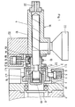
- FIG. 1 shows an axial section through the coupling according to the invention and parts of the plasticizing unit and the drive device in the engaged position
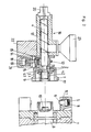
- FIG. 2 shows a similar section in the disengaged position.
- the parts belonging to the plasticizing unit 16 are the mass cylinder 12, the screw 4, the adapter sleeve 3, the driving ring 9 and the bearing bell 1.
- the screw 4 located in the plasticizing unit 16, as well as the adapter sleeve 3, the driver 9, the bearing bell 1, the radial axial bearing 2 and the calibration ring 13 form a fixed, assembled unit.
- the adapter sleeve 3 can be formed by two half-shells screwed together. Another embodiment provides that the adapter sleeve 3 in the area 3.1 and the screw 4 in the area 4.2 are provided with intermeshing splined shaft profiles. During assembly, the adapter sleeve 3 is pushed with its splined shaft profile on the splined shaft profile of the worm 4 and then rotated by 15 o. As a result, the adapter sleeve 3 is fixed on the screw 4 in the axial direction.
- the bearing bell 1 is mounted on the adapter sleeve 3 via an axial and radial bearing 2.
- the adapter sleeve 3 is connected to an annular groove 4.1 on the screw 4 in a positive and / or non-positive manner. This connection makes it possible to transmit axial forces and movements to the worm 4 from the drive shaft 8 via the adapter sleeve 3.
- the driving ring 9 is positively or non-positively connected to the worm 4 and the adapter sleeve 3 and positively to the drive shaft 8 or the stop pin 10.
- the driver ring 9 is formed with two lateral, central, parallel surfaces (so-called key surfaces), which are received in a form-fitting manner in the drive shaft 8.
- the drive shaft 8 is slit open at the front. Due to this positive locking, it is now possible to transmit torque.
- the centering and stop pin is primarily used to transmit one-sided axial forces (injection force) and secondarily to center the concentricity of the screw unit.
- the connection of the driving ring 9 with the worm 4 serves to transmit the torque.
- the connection of the driving ring 9 with the adapter sleeve 3 serves as an anti-rotation device for the adapter sleeve 3 and as a loss protection for the driving ring 9 itself if the plasticizing unit 16 has to be transported.
- the driving ring 9 is connected to the adapter sleeve 3 by means of screws.
- the bearing bell 1 is held by the attack of self-locking wedges 6, which are acted upon by springs 5.
- the wedges 6 are mounted on the machine side on the drive device 7 and engage a holding flange 17 of the bearing bell 1.
- the screw unit 1, 2, 3, 4, 9 is held in a precisely defined longitudinal position relative to the mass cylinder, i.e. calibrated.
- a calibration ring 13 is positively and / or non-positively fastened on the adapter sleeve 3.
- the adapter sleeve 3 has an external thread onto which the calibration ring 13 is screwed.
- the calibration ring 13 is held in a positive and / or non-positive manner in the calibration center 15 attached to the mass cylinder 12 during the coupling process by means of a calibration bar 14 which can be moved radially relative to the screw 4.
- the calibration bar 14 is displaced against the force of the spring 18 by a hydraulic fluid acting on the piston 19.
- the reverse construction is of course also possible. That is, instead of the calibration ring 13, the adapter sleeve 3 could have an annular groove into which a projection of the calibration bar 14 engages.
- the cylinders 21 for the calibration bar 14, the cylinder plate 2 and the measuring funnel 23 are also shown in the figures of the drawings.
Landscapes
- Engineering & Computer Science (AREA)
- Manufacturing & Machinery (AREA)
- Mechanical Engineering (AREA)
- Injection Moulding Of Plastics Or The Like (AREA)
Applications Claiming Priority (2)
| Application Number | Priority Date | Filing Date | Title |
|---|---|---|---|
| AT1470/88 | 1988-06-07 | ||
| AT147088A AT390910B (de) | 1988-06-07 | 1988-06-07 | Automatische kupplung |
Publications (2)
| Publication Number | Publication Date |
|---|---|
| EP0345630A2 true EP0345630A2 (fr) | 1989-12-13 |
| EP0345630A3 EP0345630A3 (fr) | 1991-06-05 |
Family
ID=3514601
Family Applications (1)
| Application Number | Title | Priority Date | Filing Date |
|---|---|---|---|
| EP19890109894 Withdrawn EP0345630A3 (fr) | 1988-06-07 | 1989-06-01 | Accouplement automatique |
Country Status (2)
| Country | Link |
|---|---|
| EP (1) | EP0345630A3 (fr) |
| AT (1) | AT390910B (fr) |
Cited By (2)
| Publication number | Priority date | Publication date | Assignee | Title |
|---|---|---|---|---|
| EP1074335A3 (fr) * | 1999-07-08 | 2002-05-22 | Meltog Limited | Changement de mandrin et d'outil et dispositif pour cela |
| WO2020041886A1 (fr) | 2018-08-30 | 2020-03-05 | Husky Injection Molding Systems Ltd. | Distributeur de matière fondue pour le moulage de plastiques |
Families Citing this family (1)
| Publication number | Priority date | Publication date | Assignee | Title |
|---|---|---|---|---|
| AT521960B1 (de) | 2019-01-11 | 2020-07-15 | Engel Austria Gmbh | Kupplungselement |
Family Cites Families (1)
| Publication number | Priority date | Publication date | Assignee | Title |
|---|---|---|---|---|
| CH653948A5 (de) * | 1981-09-28 | 1986-01-31 | Netstal Ag Maschf Giesserei | Kupplungsvorrichtung zwischen antriebsvorrichtung und schnecke der plastifiziereinheit einer spritzgiessmaschine. |
-
1988
- 1988-06-07 AT AT147088A patent/AT390910B/de not_active IP Right Cessation
-
1989
- 1989-06-01 EP EP19890109894 patent/EP0345630A3/fr not_active Withdrawn
Cited By (6)
| Publication number | Priority date | Publication date | Assignee | Title |
|---|---|---|---|---|
| EP1074335A3 (fr) * | 1999-07-08 | 2002-05-22 | Meltog Limited | Changement de mandrin et d'outil et dispositif pour cela |
| WO2020041886A1 (fr) | 2018-08-30 | 2020-03-05 | Husky Injection Molding Systems Ltd. | Distributeur de matière fondue pour le moulage de plastiques |
| CN113195195A (zh) * | 2018-08-30 | 2021-07-30 | 赫斯基注塑系统有限公司 | 用于塑料模制的熔体分配器 |
| EP3843970A4 (fr) * | 2018-08-30 | 2022-06-29 | Husky Injection Molding Systems Luxembourg IP Development S.à.r.l | Distributeur de matière fondue pour le moulage de plastiques |
| CN113195195B (zh) * | 2018-08-30 | 2023-03-10 | 赫斯基注塑系统有限公司 | 用于塑料模制的熔体分配器 |
| US11981062B2 (en) | 2018-08-30 | 2024-05-14 | Husky Injection Molding Systems Ltd | Melt dispenser for plastic molding |
Also Published As
| Publication number | Publication date |
|---|---|
| EP0345630A3 (fr) | 1991-06-05 |
| AT390910B (de) | 1990-07-25 |
| ATA147088A (de) | 1990-01-15 |
Similar Documents
| Publication | Publication Date | Title |
|---|---|---|
| DE3626851C2 (de) | Befestigungsvorrichtung für rotative Schleifwerkzeuge, insbesondere Schleifscheiben, auf einer Spindel | |
| DE3545651C2 (fr) | ||
| EP0164792B1 (fr) | Dispositif pour l'accouplement positif de deux arbres | |
| DE19625318C2 (de) | Konusschraubverbindung für Lamellenpaket-Wellenkupplungen | |
| DE2729939C3 (de) | Kraftbetätigtes Spannfutter | |
| EP2015047A2 (fr) | Procédé et dispositif de centrage et de fixation d'une pièce à usiner dans une machine d'équilibrage | |
| EP0155539A1 (fr) | Dispositif porte-outil à support d'outil interchangeable | |
| DE2106933B2 (de) | Vorrichtung zum Verdrehen einer Welle, insbesondere eines Ventilschafts | |
| DE19636594A1 (de) | Löseeinheit | |
| CH637049A5 (de) | Spanndorn fuer die koaxiale aussenbearbeitung von werkstuecken mit definierter innenverzahnung. | |
| DE3300227A1 (de) | Vorrichtung zur loesbaren verbindung von greiferschienenteilen der greiferschienen in einer transfer-presse | |
| DE2234321B1 (de) | Zahnärztliches Handstuck | |
| DE1099806B (de) | Spannsatz zwischen einem zylindrischen Bauteil und einem dazu konzentrisch angeordneten Koerper | |
| EP0040808A1 (fr) | Cylindre | |
| DE1602825C3 (de) | Vorrichtung zur lösbaren Befestigung eines Spannfutters | |
| DE1919439C3 (de) | Schnellspannfutter für einen Schaft aufweisende Werkzeuge | |
| EP0345630A2 (fr) | Accouplement automatique | |
| DE3729093C1 (de) | Spannvorrichtung mit mechanischem Kraftverstaerker | |
| WO2000048776A1 (fr) | Dispositif permettant d'assembler de façon amovible un outil avec une broche de machine | |
| DE851579C (de) | Vorrichtung zur Aufhebung des axialen Spiels von Getrieben | |
| DE661868C (de) | Vorrichtung zum Auf- und Abschrauben von Werkstueckteilen | |
| DE3328397A1 (de) | Kupplungsvorrichtung zur drehmomentuebertragenden verbindung zweier wellen | |
| DE2644178C3 (de) | Einrichtung zur Klemmung einer vorschubbeweglichen Werkzeugspindelhülse | |
| CH661676A5 (en) | Screw connection on a boring tool and its adaptor | |
| DE3808769C2 (fr) |
Legal Events
| Date | Code | Title | Description |
|---|---|---|---|
| PUAI | Public reference made under article 153(3) epc to a published international application that has entered the european phase |
Free format text: ORIGINAL CODE: 0009012 |
|
| AK | Designated contracting states |
Kind code of ref document: A2 Designated state(s): AT BE CH DE FR GB IT LI NL SE |
|
| PUAL | Search report despatched |
Free format text: ORIGINAL CODE: 0009013 |
|
| AK | Designated contracting states |
Kind code of ref document: A3 Designated state(s): AT BE CH DE FR GB IT LI NL SE |
|
| STAA | Information on the status of an ep patent application or granted ep patent |
Free format text: STATUS: THE APPLICATION IS DEEMED TO BE WITHDRAWN |
|
| 18D | Application deemed to be withdrawn |
Effective date: 19911206 |