EP0345672B1 - Générateur d'adresse - Google Patents
Générateur d'adresse Download PDFInfo
- Publication number
- EP0345672B1 EP0345672B1 EP89110069A EP89110069A EP0345672B1 EP 0345672 B1 EP0345672 B1 EP 0345672B1 EP 89110069 A EP89110069 A EP 89110069A EP 89110069 A EP89110069 A EP 89110069A EP 0345672 B1 EP0345672 B1 EP 0345672B1
- Authority
- EP
- European Patent Office
- Prior art keywords
- address generator
- scan
- address
- count
- line
- Prior art date
- Legal status (The legal status is an assumption and is not a legal conclusion. Google has not performed a legal analysis and makes no representation as to the accuracy of the status listed.)
- Expired - Lifetime
Links
Images







Classifications
-
- G—PHYSICS
- G06—COMPUTING OR CALCULATING; COUNTING
- G06F—ELECTRIC DIGITAL DATA PROCESSING
- G06F9/00—Arrangements for program control, e.g. control units
- G06F9/06—Arrangements for program control, e.g. control units using stored programs, i.e. using an internal store of processing equipment to receive or retain programs
- G06F9/30—Arrangements for executing machine instructions, e.g. instruction decode
- G06F9/34—Addressing or accessing the instruction operand or the result ; Formation of operand address; Addressing modes
- G06F9/345—Addressing or accessing the instruction operand or the result ; Formation of operand address; Addressing modes of multiple operands or results
-
- G—PHYSICS
- G06—COMPUTING OR CALCULATING; COUNTING
- G06T—IMAGE DATA PROCESSING OR GENERATION, IN GENERAL
- G06T1/00—General purpose image data processing
- G06T1/60—Memory management
Definitions
- the present invention relates to an address generator.
- One such address generator for a real time video digital map display is known from GB-A-2 113 056. There, the address generator provides addresses which allow scanning of the pattern of stored data only in a predetermined orientation.
- EP-A-0 341 645 Another address generator is disclosed in EP-A-0 341 645.
- an addressable memory is scanned in rows or columns parallel to the rectangular matrix in which the data is stored.
- to provide a rotated image, or one which is not symmetrically scanned with respect to the memory plane requires extensive additional processing and computational time.
- US-A-4,477,802 Another address generator adapted for use in a digital map display system is taught in US-A-4,477,802.
- This invention discloses an address generator capable of generating addresses which lie along parallel lines angularly disposed with respect to the orientation of the rows and columns of storage elements in the memory.
- this invention does not provide for generating areas having an asymmetrical or non-rectangular configuration and provides for generation only of sequential addresses. Thus, it is not suitable for applications which process image data bilinearly and hence scan the stored addresses non-sequentially.
- the aforesaid invention does not provide for reading from a first memory and writing into a second full field memory, and can update map data only one row or column at a time between successive fields of displayed map data.
- the screen or display space of the display device may be thought of as comprising a plurality of picture elements or cells (sometimes called "pixels") arranged in rows and columns. Each point may therefore be defined by the X and Y coordinates of a Cartesian grid.
- Data representing, for example, the intensity or color of light to be displayed at each particular segment of the screen may be produced in a known manner and stored in a random-access memory of a general purpose computer, along with data representing the X and Y coordinates of that element's position on the screen.
- the computer transfers the image information to a frame buffer or storage array, the individual elements of which are arranged to form a Cartesian grid corresponding to the Cartesian grid formed by the picture elements or raster of the display screen.
- a display control unit retrieves the data from the display buffer in accordance with the particular raster of the display device and activates the display device to display an image corresponding to the data stored in the frame buffer.
- the X and Y coordinate data stored in the computer determines the position in the frame buffer in which each unit of image data is stored and the pattern of data stored in the frame buffer determines the image to be displayed.
- the problem being confronted was the means required in a digital map computer to scan out of a cache memory an arbitrarily rotated and zoomed pattern which maintained a fixed resolution.
- These patterns include a trapezoidal pattern for the generation of a perspective view of digital terrain data, a star pattern for the overlay of an intervisibility function, and a rectangluar pattern for a top-down plan view of digitized aeronautical charts and digital terrain data.
- the mismatch between the regular Cartesian pixel grid array of cache memory and the various patterns required for the display formats had to be compensated for in such a manner that the displayed image remained smooth and stable under animation.
- the known prior art has not attempted to support the programmability of the patterns nor the variety of patterns available in the present invention.
- the perspective view format has been implemented previously via a radial scan pattern similar to the star pattern of this invention.
- Each ray projected from the viewpoint onto cache memory corresponds to a column of pixels on the display device.
- Each sample along the ray corresponds to a row of pixels on the display device.
- plan view has been implemented previously with a parallel scan algorithm similar to the rectangular pattern algorithm presented here.
- the nearest neighbors surrounding the calculated scan address of the cache memory addresses is determined.
- the terrain data is then transferred to the display control unit for graphic rendering and display.
- the object of the present invention to devise an address generator which generates scan parameters being programmable for providing a predetermined scan pattern.
- This invention differs from the prior methods of perspective view generation in that a trapezoidal scan pattern is used instead of the radial scan method.
- the trapezoidal pattern is generated by an orthographic projection of the truncated view volume onto the cache memory (terrain data).
- the radial scan concept is retained, but used for an intervisibility overlay instead of the perspective view generation.
- the radial scan is enhanced to include a full 360 degree arc with programmable attributes.
- the rectangular pattern retains the parallel scan methodology for plan view map generation. Both a nearest neighbor and a full bilinear interpolation method of scan address generation are implemented.
- the shortcomings of the prior method of perspective view generation are solved by this invention.
- the interior scan pattern of the trapezoid is locked to the horizontal axis of the cache memory. This guarantees that the terrain data posts selected (cache memory addresses) are consistent from frame to frame under animation.
- the image quality of the plan view rectangular parallel scan can be more precisely controlled by selecting either a nearest neighbor algorithm or the full bilinear interpolation algorithm. Under bilinear interpolation, the four nearest neighbors in cache memory are selected surrounding the generated scan address and used to calculate an intermediate point instead of the default selection under single nearest neighbor.
- the additional radial pattern for intervisibility is implemented with programmable attributes to accomodate a variety of mission requirements.
- the invention solves a number of problems in the area of digital map display generation.
- the address generator supports perspective view, intervisibility, plan view, data frames, and aeronautical chart display formats while minimizing hardware. It retains full programmability of aircraft parameters and view selection attributes such as roll, pitch, heading, position, slew, view angle, look down angle, front and back clipping planes, and zoom. It maintains high image quality (1K x 1K resolution) while scanning patterns at a 20 ⁇ Hertz frame update rate. The nature of the patterns scanned out for further processing guarantees the frame to frame coherence of the animation, eliminating boiling, strobing, and greatly reducing aliasing artifacts.
- the invention can be applied to any system requiring rapid memory-to-memory block transfer of data in arbitrary patterns.
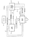
- Fig. 1 is a block diagram showing the present invention and its interface with a digital map display system.
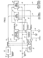
- Fig. 2 is a block diagram showing a preferred embodiment of the present invention.
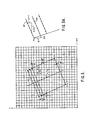
- Fig. 3 is a diagram showing a rectangular scan pattern generated by the present invention.
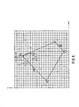
- Fig. 4 is a diagram showing a trapezoidal scan pattern generated by the present invention.
- Fig. 5 is a diagram showing a star scan pattern generated by the present invention.
- Fig. 6 shows the details of the X and Y read address generators.
- Fig. 7 shows the details of the X and Y write address generators.
- Fig. 8 shows the details of the X and Y line counters.
- Fig. 9 is a block diagram of the timing and sequence generator.
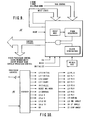
- Fig. 10 ⁇ shows details of the output parameters generated by the decoder.
- Fig. 11 is a waveform diagram of clock signals generated by the timing and sequence generator.
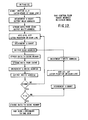
- Fig. 12 is a flow chart showing operation in the nearest neighbor mode.
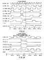
- Figs. 13 and 14 are timing diagrams for the nearest neighbor mode.
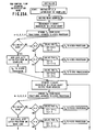
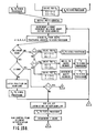
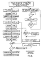
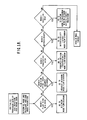
- Figs. 15 A-D are flow charts showing operation in the bilinear interpolation mode.
- Fig. 16 is a flow chart showing operation in the perspective view scan mode.
- Fig. 17 is a flow chart showing operation in the intervisibility or radial scan mode.
- Fig. 18 is a top-down flow chart showing selection of a desired mode of operation.
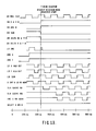
- Fig. 19 is timing diagram showing the phase relation between waveforms generated by the timing and sequence generator.
- Address generator 20 ⁇ receives instructions and control signals from a processor 22 via address and data bus 24.
- the processor 22 can be designed in the form of a microprocessor which receives aircraft and map data in digital form from an auxiliary airborne computer (not shown).
- the bus 24 also provides address and data signals and receives status information from cache memory 26 and display buffer 28.
- Address generator 20 ⁇ provides read address commands along X and Y Cartesian coordinates which form a rectangular matrix via bus 30 ⁇ and read clock strobe 80 ⁇ to cache memory 26, and write addresses and control signals to display buffer 28.
- the data read out of cache memory 26 is coupled into display buffer 28 via data bus 32.
- Display buffer 28 feeds a full-field bit-mapped memory (not shown) via data bus 34.
- Display data is extracted from the cache memory 26 and transferred to the bit-mapped memory in blocks, controlled by the address generator 20 ⁇ , which outputs a write address 74 and write clock strobe 78 to write the data and control signals 76 into the display buffer 28 and bit-mapped memory at a specified location.
- Decoder 40 ⁇ provides output commands such as initialization of the initial X and Y coordinate starting points, and initial X and Y pixel and line count and scan mode. Decoder 40 ⁇ is a set of gates for routing information from a single source to different destinations at different times. Such a circuit is also referred to as a demultiplexer. Such demultiplexers are available as standard integrated circuit components which can be configured in arrays to decode any size data words.
- the address generator 20 ⁇ consists essentially of five function blocks: a front-end processor 44, a read address generator 46, a write address generator 48, X and Y line counters 50 ⁇ and a timing and sequencer controller 52.
- the commands from decoder 40 ⁇ are coupled to read address generator 46 and write address generator 48 on bus 54. Further commands to timing and sequence controller 52 are applied on bus 56 and to front-end processor 44 via bus 58.
- Line counters 50 ⁇ receive initialization commands and send status commands on bus 60 ⁇ to data bus 62, which is energized by the processor 22.
- Front-end processor 44 which may comprise addressable sine and cosine lookup tables, provides computed control parameters to read address generator 46 and write address generator 48 on bus 64.
- Timing and sequence controller 52 distributes the priorities of access to the read and write generators via lines 66 and 68 and to the line counters via line 70 ⁇ .
- Line counter status such as X DONE, Y DONE, is returned via line 72.
- Timing and sequence controller 52 provides the control timing and clock signals required by the various other circuit elements.
- the control logic can be designed by well known techniques.
- Processor 22 also controls timing and sequence controller 52 by initiating performance and specifying what scan mode is to be performed.
- read address generator 46 The output of read address generator 46 is applied to the cache memory 26 via bus 30 ⁇ .
- Write address generator 48 provides a write address via bus 74 to display buffer 28.
- FIG. 3 there is shown a graphical illustration of the parameters involved in addressing the cache memory 26.
- the point Xo, Yo represents the map center.
- the arrows X and Y represent the orthogonal axes of the logical cache memory storage array.
- the array is seen to be configured as nine segments, each comprised of 64 bytes, each byte having a unique address.
- the storage segments are arranged along rows parallel to the X axis and columns parallel to the Y axis.
- Points P1, P2, P3, and P4 represent the corners of a rectangular envelope 80 ⁇ disposed at an angle 0 ⁇ r with respect to the X, Y coordinate system.
- the storage location represented by the point P1 represents the address of the storage element where a scan line of the cache memory 26 is to begin to read the map data encompassed by envelope 80 ⁇ and the point P2 represents the address of the storage element where the scan line ends. It may be seen that each scan line originates from a different point along the line P1 - P3 of the envelope 80 ⁇ .
- the number of origin points corresponds to the number of scan lines.
- the number of storage elements along each scan line corresponds to the number of displayable picture elements (pixels).
- the number of scan lines corresponds to the number of displayable scan lines in a complete frame.
- a scan line 82 is seen to originate at point P1.
- the slope of line 82 is defined in conventional manner by the tangential components with respect to the horizontal X axis.
- ⁇ YY defines the vertical displacement with respect to an arbitrary horizontal measure ⁇ XX.
- the parameters ⁇ YY and ⁇ XX may be dynamically varied by the processor 22, thereby providing a flexible and programmable line-to-line scan capacity. For the rectangular scan mode, parameters ⁇ XX and ⁇ YY will be held constant.
- the slope of the points of origin between successive scan lines 82 and 84 is defined by the tangential components ⁇ X and ⁇ Y. Varying the ratio of ⁇ X and ⁇ Y or their individual magnitudes will vary the slope of the sides of the envelope 80 ⁇ . These parameters are also programmable by the processor 22.
- Fig. 4 shows a graphical representation of a trapezoidal scan envelope 90 ⁇ .
- the points P1, P2, P3, and P4 define the contour of the area to be scanned. However, in the trapezoidal mode the scan lines are oriented parallel to the X axis to permit a 1:1 correspondence with the segmented storage elements.
- the parameter ⁇ XX is set to 1, and ⁇ YY is set to 0 ⁇ .
- the slope of a side 92 of the trapezoid 90 ⁇ is determined by the parameters ⁇ X and ⁇ Y.
- ⁇ Y is set to 1 and ⁇ X will determine the slope of side 92. In this manner, the segmented storage elements of the cache memory are locked to the map display, and the same polygon will be generated from frame to frame.
- a star or radial scan pattern which may be used, for example, for overlaying a target pattern on a terrain display, is generated as shown in Fig. 5.
- An origin 0,0 at a center point P1 of the display and a radius defining the scan line P1 - P2 is calculated by the processor 22. Start and stop angles or an angle of change ⁇ may also be defined.
- the input commands are applied to processor 44 where sine and cosine lookup tables generate the corresponding parameters ⁇ XX and ⁇ YY defining the slope of each successive scan line.
- the display may be modulated based on aircraft altitude, sensor, and terrain height by providing a data flag corresponding to the address generated by the address generators.
- read address generator 46 is basically an arithmetic logic unit which performs a series of incremental adds after receiving a starting X, Y point, scan line slope or pixel-to-pixel increment ⁇ XX, ⁇ YY values, and line-to-line slope increment values ⁇ X, ⁇ Y, which is the pixel-to-pixel distance betwen scan line starting points, from the processor data bus 62.
- the initial X and Y starting points are calculated by the processor airborne computer 22 using a normalized coordinate system and the aircraft heading information. These initial values are then loaded into the respective X and Y registers 90 ⁇ .
- Processor 22 also calculates four corner points (P1, P2, P3, P4) based on the scale, center/decenter mode, zoom, heading, and aircraft position.
- the four cache point addresses surrounding the calculated point position for a bilinear interpolation or the nearest neighbor processing are calculated by methods well known in the art. See, for example, U.S. Patent No. 4,528,693, and Digital Picture Processing , Rosenfeld and Kak, 2nd Ed., Vol. 2, pp . 33-36. While Fig. 6 refers to the X coordinate address generator, the Y coordinate generator functions in an identical manner, except that the parameters loaded are, of course, the Y axis increments and starting point.
- Processor 44 comprises addressable sine and cosine PROM'S which receive angular parameters from the data bus 62 for calculating the linear coordinate increments in the star display mode.
- Processor 44 uses the input data parameters from the airborne computers (i.e. mode and four corner points or center point, radius, angle of change, and start/stop angles). These parameters are used to set default values or calculate the parameters used by the address generator: ⁇ XX, ⁇ YY (scan line slope); ⁇ X, ⁇ Y (slope from scan line to scan line); line lengths; and number of lines.
- the X read address generator 46 generates addresses to read from cache memory, passes value through (adds zero), adds one to the previous address and adds a delta value to a previous address.
- Delta value can be positive or negative and can be any absolute value from zero to 3.999 (approximately).
- these addresses can be generated as across a line or aspects of four points across a line set up as (X,Y), (X+1,Y), (X,Y+1), (X+1,Y+1).
- the addresses can be generated at 10 ⁇ 0 ⁇ nanosecond time intervals.
- a rectangular, trapezoidal, or star shape of points can be created with any orientation.
- Fig. 7 shows the details of the X and Y write address generators
- Fig. 8 shows details of the X and Y line counters.
- X and Y count parameters are provided on bus 116 from the airborne computer.
- the X count is loaded into a latch and stored by the LD X count command from decoder 40 ⁇ .
- the value stored in latch 130 ⁇ represents the number of pixels in a line, which corresponds to the lengthj of the line for a given pixel-to-pixel increment.
- the value in latch 130 ⁇ is applied to load an initial X count into counter 132 on an INITIALIZE command from decoder 40 ⁇ applied to gate 134.
- counter X is decremented after each address is generated along the scan line until a count of 1 is reached, indicative of the end of the scan line.
- This signal applied to PROM 136 is indicative of the completion of data transfer from the cache memory along the scan line.
- Y count 138 is loaded and decremented after the completion of each scan line.
- Counter 138 is initialized with a count indicative of the number of scan lines in a frame, while PROM 140 ⁇ provides a signal when the complete frame of data has been transferred.
- the X count In the display list mode, typically the X count would be comprised of 256 pixels and the Y count would be comprised of 4 lines. In the map display mode, the X count is typically 484 pixels and the Y count also 484 pixels. The count is adjusted by the airborne computer to allow for the display mode, such as bilinear interpolation, and high resolution or low resolution operational modes.
- the outputs of the X and Y counters provide a signal X DONE indicating the end of each scan line count and Y DONE indicating when a block transfer operation is complete.
- the counters In the map mode, the counters are loaded to take into consideration the additional counting steps needed to find the four points around each address used for bilinear interpolation, and a BILINEAR DONE signal is generated.
- the write address generators consist of counters used to provide addresses to a full-field bit mapped scene memory for the transfer of display data or to an overlay memory for the transfer of overlay data. They are clocked directly by the timing generator and state sequencer 52.
- a X write counter 10 ⁇ 0 ⁇ and a Y write counter 124 are coupled to a reset line 10 ⁇ 4 which is fed by the decoder 40 ⁇ . On reset the counters are cleared to accept a new count sequence.
- Timing and sequence generator 52 provides a 10 ⁇ MHz clock X signal on line 10 ⁇ 6 to the X write counter and a 10 ⁇ MHz clock Y signal on line 10 ⁇ 8 to the Y write counter.
- the output of X counter 10 ⁇ 0 ⁇ is coupled to a first buffer 110 ⁇ which is enabled by a read signal 112 from the decoder 40 ⁇ . This provides a signal indicative of the X write counter status to data bus 114.
- the output of X write counter 10 ⁇ 0 ⁇ is coupled on line 118 to a second buffer 120 ⁇ . Buffer 120 ⁇ when activated by a write enable strobe from timing generator and sequence controller 52 applies an X write address to the display full-field memory (not shown).
- the Y write counter circuit comprised of counter 124 and buffers 126 and 128, operates in a manner similar to the X write counter circuit, hence need not be described in detail.
- the address generator circuit is provided with all of the necessary control signals and clocks required for its operation during the different modes.
- a 40 ⁇ MHz oscillator is divided to provide a controlling 10 ⁇ MHz clock frequency and several phases of the 10 ⁇ MHz clock.
- the sequencer 52 also provides control signals to a video processor for use in its bilinear interpolation circuitry, clock signals to the cache and scene memories to read or write data, 10 ⁇ MHz clocks, control signals to the overlay processor to transfer display lists, and clock signals to the video processor and to the overlay processor.
- the multiplexed inputs include X done, Y done, bilinear done, last line, address generator done, and other related signals.
- Fig. 10 ⁇ shows the output commands generated by the decoder 40 ⁇ in response to the parameters from the airborne computer.
- Fig. 11 shows the clock signals generated by the timing and sequence generator 52.
- Fig. 12 shows a flow chart for the nearest neighbor mode
- Figs. 13 and 14 are timing diagrams for the nearest neighbor mode.
- Figs. 15 A-D are flow charts for the bilinear interpolation mode.
- Figs. 16 and 17 are flow charts showing operation in the perspective view and radial scan view modes, respectively, while Fig. 18 is a top-down flow chart showing selection of a desired mode of operation.
- Fig. 19 is a timing diagram showing the relation of waveforms generated by the timing generator and sequence controller 52.
Landscapes
- Engineering & Computer Science (AREA)
- Theoretical Computer Science (AREA)
- Physics & Mathematics (AREA)
- General Physics & Mathematics (AREA)
- Software Systems (AREA)
- General Engineering & Computer Science (AREA)
- Image Generation (AREA)
- Image Input (AREA)
- Digital Computer Display Output (AREA)
- Memory System (AREA)
- Memory System Of A Hierarchy Structure (AREA)
- Controls And Circuits For Display Device (AREA)
- Control Of Indicators Other Than Cathode Ray Tubes (AREA)
Claims (12)
- Générateur d'adresse pour un système de cartographie numérique qui balaye une première mémoire adressable (26) configurée de manière logique en une matrice rectangulaire dans laquelle un motif de données est stocké dans une orientation prédéterminée par rapport à ladite matrice, et écrit dans une deuxième mémoire adressable (28) comportant:des moyens d'entrée (42, 62) destinés à recevoir des paramètres de motif de balayage provenant d'une source externe, lesdits paramètres étant programmables afin de procurer une multiplicité de motifs de balayage sensiblement indépendants de ladite orientation prédéterminée,des moyens de traitement (44) contenant des tables de consultation de sinus et cosinus et couplés de façon à recevoir lesdits paramètres pour le calcul d'angles d'une enveloppe définissant le contour d'un motif de balayage et d'angles de rotation pour des lignes successives dudit motif de balayage,des moyens de génération d'adresse de lecture (46) qui répondent auxdits moyens de traitement (44) afin de générer de manière sélective des signaux d'adresse de façon à lire ladite information de motif dans une direction donnée par rapport à ladite orientation prédéterminée, ladite direction donnée étant sensiblement indépendante de ladite orientation prédéterminée, et afin de procurer des valeurs incrémentales horizontales et verticales d'adresses de lecture de façon à générer chaque ligne dudit motif de balayage et lire des valeurs de signaux numériques stockées dans ladite première mémoire (26) à des adresses correspondantes,des moyens de génération d'adresse d'écriture (48) couplés de façon à recevoir lesdits paramètres sous la forme d'un premier paramètre définissant un point de départ d'une première ligne de balayage, un deuxième paramètre définissant la pente de ladite ligne de balayage, et un troisième paramètre définissant la pente de points de départ d'une ligne de balayage successive, lesdits premier, deuxième et troisième paramètres étant variables de manière dynamique et séquentielle en fonction de signaux de commande provenant de ladite source externe afin de former un motif de ladite multiplicité de motifs de balayage, afin de générer des adresses d'écriture séquentielle de façon à écrire dans ladite deuxième mémoire adressable (28) configurée en matrice rectangulaire,des moyens de comptage (50) destinés à compter le nombre d'adresses incrémentales en fonction d'une longueur de ligne prédéterminée et le nombre de lignes de balayage en fonction d'un compte de ligne prédéterminé et destinés à procurer un signal indicatif de la fin d'une ligne de balayage et un signal indicatif de la génération d'une trame complète à la fin dudit compte de lignes, etdes moyens de cadencement (52) destinés à générer des signaux de cadencement et de séquencement afin de générer chaque ligne de balayage, lire ladite première mémoire adressable le long desdites lignes de balayage, et écrire le contenu de ladite mémoire adressable dans ladite deuxième mémoire adressable.
- Générateur d'adresse selon la revendication 1, caractérisé en ce que lesdits paramètres appliqués auxdits moyens de traitement (44) comportent les points de coin (P1, P2, P3, P4) d'une figure géométrique.
- Générateur d'adresse selon la revendication 2, caractérisé en ce que ladite figure géométrique comporte un rectangle (80).
- Générateur d'adresse selon la revendication 2, caractérisé en ce que ladite figure géométrique comporte un trapèze (90).
- Générateur d'adresse selon la revendication 2, caractérisé en ce que ladite figure géométrique comporte au moins une partie d'une étoile ayant plusieurs éléments s'étendant radialement, et lesdits paramètres comportent un point central, un rayon de ligne et un angle inclus ou un angle de début et un angle de fin définissant un angle inclus.
- Générateur d'adresse selon la revendication 2, caractérisé en ce que lesdites tables de consultation répondent à des paramètres d'adresse afin de générer des valeurs de pentes desdits angles sous forme de coordonnées cartésiennes.
- Générateur d'adresse selon la revendication 4, caractérisé en ce que lesdites lignes de balayage ont une pente de zéro par rapport à un axe horizontal de ladite matrice rectangulaire et la pente d'un bord (92) dudit trapèze défini par ladite enveloppe par rapport audit axe horizontal détermine les points de début et de fin des lignes de balayage successives (figure 4).
- Générateur d'adresse selon la revendication 3, caractérisé en ce que des lignes de balayage successives sont balayées en parallèle l'une par rapport à l'autre, mais pas nécessairement parallèlement à un axe de ladite matrice rectangulaire, et la pente d'un bord (82) dudit rectangle définit les points de début ou de fin de lignes de balayage successives (figure 3).
- Générateur d'adresse selon la revendication 1, caractérisé en ce que lesdits moyens de génération d'adresse de lecture (46) comportent:un générateur d'adresse de lecture X et un générateur d'adresse de lecture Y destinés à recevoir des paramètres représentatifs de l'adresse de début d'une ligne de balayage, des premières valeurs de correction incrémentales X et Y (ΔXX, ΔYY) correspondant à une pente de ladite ligne de balayage, et des deuxièmes valeurs de correction incrémentales X et Y (ΔX, ΔY) correspondant à la pente relative des lignes de balayage successives,des moyens destinés à calculer des adresses de lecture correspondant à au moins une desdites lignes de balayage en additionnant les adresses de début X ou Y respectives et des premières valeurs incrémentales X ou Y correspondantes et incrémentant de manière séquentielle lesdites adresses de lecture additionnées avec lesdites premières valeurs incrémentales,des moyens qui répondent à la fin d'une ligne de balayage afin d'additionner les points de début X ou Y respectifs et des deuxièmes valeurs incrémentales X ou Y correspondantes, définissant ainsi le début d'une ligne de balayage successive, etdes moyens destinés à incrémenter de manière séquentielle lesdites adresses de lecture en additionnant lesdites première et deuxième valeurs incrémentales X et Y avec des adresses de lecture X et Y correspondantes jusqu'à ce qu'une multiplicité prédéterminée de lignes de balayage définissant une trame soit terminée (figure 6).
- Générateur d'adresse selon la revendication 9, caractérisé en outre par:
des moyens destinés à adresser de manière séquentielle plusieurs emplacements de mémorisation desdits deuxièmes moyens de mémoire adressable (28) de la forme P1 = X,Y, P2 = X+1,Y, P3 = X,Y+1, P4 = X+1,Y+1, lesdits points avoisinant un point correspondant à la valeur de l'emplacement de stockage dans lesdits moyens de mémoire. - Générateur d'adresse selon la revendication 1, caractérisé en ce que lesdits moyens de comptage (50) comportent:des moyens de verrouillage (130) destinés à recevoir et mémoriser un compte X initial correspondant à ladite longueur de ligne provenant desdits moyens d'entrée (116), lesdits moyens de verrouillage répondant également à un signal de commande 131 provenant desdits moyens d'entrée afin de retourner ou décrémenter ledit compte initial,des premiers moyens de comptage préréglables (132) qui répondent auxdits moyens d'entrée afin d'être préréglés audit compte initial X et qui répondent auxdits moyens de verrouillage (130) afin de procurer un compte X décrémenté,des premiers moyens logiques (136) couplés auxdits premiers moyens de comptage préréglables afin de détecter quand un compte X prédéterminé a été ainsi atteint et afin de procurer un signal indiquant la fin d'une ligne de balayage et destiné à réinitialiser le compte desdits premiers moyens de comptage à un autre compte X initial pour une ligne de balayage successive, des seconds moyens de comptage préréglables (138) qui répondent auxdits moyens d'entrée afin d'être préréglés à un compte initial Y correspondant au nombre de lignes de balayage dans un cadre et qui répondent en outre auxdits moyens d'entrée (116) afin de procurer un compte Y décrémenté et des seconds moyens logiques (140) couplés auxdits seconds moyens de comptage afin de détecter quand un compte Y prédéterminé a été atteint, afin de procurer ainsi un signal indiquant la lecture d'une trame complète de façon à écrire le contenu desdits moyens de mémoire adressable supplémentaires dans lesdits moyens d'affichage (figure 8).
- Générateur d'adresse selon la revendication 1, caractérisé en ce que ledit générateur d'adresse d'écriture comporte en outre:des moyens (106, 108) reliés auxdits moyens de cadencement (52) afin de recevoir des impulsions d'horloge régulières,des moyens de comptage d'adresse (100, 124) destinés à compter lesdites impulsions d'horloge afin de produire une adresse pour ladite deuxième mémoire adressable (28),des moyens (120, 128) destinés à délivrer ladite adresse à ladite deuxième mémoire adressable (28) afin de désigner une adresse correspondant à un emplacement de stockage dans lequel des données stockées doivent être écrites, etdes moyens (122) couplés auxdits moyens de cadencement afin de valider de manière sélective lesdits moyens destinés à délivrer une adresse (figure 7).
Applications Claiming Priority (2)
| Application Number | Priority Date | Filing Date | Title |
|---|---|---|---|
| US07/203,660 US4884220A (en) | 1988-06-07 | 1988-06-07 | Address generator with variable scan patterns |
| US203660 | 1988-06-07 |
Publications (3)
| Publication Number | Publication Date |
|---|---|
| EP0345672A2 EP0345672A2 (fr) | 1989-12-13 |
| EP0345672A3 EP0345672A3 (fr) | 1992-03-25 |
| EP0345672B1 true EP0345672B1 (fr) | 1997-01-29 |
Family
ID=22754824
Family Applications (1)
| Application Number | Title | Priority Date | Filing Date |
|---|---|---|---|
| EP89110069A Expired - Lifetime EP0345672B1 (fr) | 1988-06-07 | 1989-06-03 | Générateur d'adresse |
Country Status (5)
| Country | Link |
|---|---|
| US (1) | US4884220A (fr) |
| EP (1) | EP0345672B1 (fr) |
| JP (1) | JP2909510B2 (fr) |
| CA (1) | CA1315005C (fr) |
| DE (1) | DE68927723T2 (fr) |
Families Citing this family (14)
| Publication number | Priority date | Publication date | Assignee | Title |
|---|---|---|---|---|
| US5093915A (en) * | 1988-11-02 | 1992-03-03 | Xerox Corporation | Method for selectively loading bootable fiber to control apparatus based upon the corresponding bootable attributes |
| US5163129A (en) * | 1989-10-06 | 1992-11-10 | Sun Microsystems, Inc. | Method for expediting the rendering of figures in a move-draw language |
| US5179638A (en) | 1990-04-26 | 1993-01-12 | Honeywell Inc. | Method and apparatus for generating a texture mapped perspective view |
| JPH0455986A (ja) * | 1990-06-26 | 1992-02-24 | Toshiba Corp | 画像処理装置 |
| KR930000994B1 (ko) * | 1990-08-09 | 1993-02-12 | 삼성전자 주식회사 | Cd-rom 데이타 버퍼링 및 독출용 어드레스 발생방법 및 회로 |
| DE69226839T2 (de) * | 1991-04-15 | 1999-04-22 | Oki Electric Industry Co., Ltd., Tokio/Tokyo | Bildverarbeitungsgerät |
| IL112186A (en) * | 1994-01-18 | 1998-09-24 | Honeywell Inc | A device for calculating inter-point vision |
| DE69840718D1 (de) * | 1997-05-28 | 2009-05-20 | Koninkl Philips Electronics Nv | Anzeigevorrichtung |
| US6111583A (en) | 1997-09-29 | 2000-08-29 | Skyline Software Systems Ltd. | Apparatus and method for three-dimensional terrain rendering |
| US20030158786A1 (en) | 1999-02-26 | 2003-08-21 | Skyline Software Systems, Inc. | Sending three-dimensional images over a network |
| US6745315B2 (en) * | 2001-08-14 | 2004-06-01 | Motorola Inc. | Generation of address pattern through employment of one or more parameters to store information at parts of storage that are employable with multiprocessing |
| JP3703754B2 (ja) | 2001-10-23 | 2005-10-05 | 富士通株式会社 | 描画装置および情報処理装置 |
| US8660719B2 (en) * | 2012-03-01 | 2014-02-25 | The Boeing Company | Four-dimensional flyable area display system for aircraft |
| US10311307B2 (en) * | 2015-06-23 | 2019-06-04 | Raytheon Company | Methods and apparatus for video wall with feed indicators |
Family Cites Families (9)
| Publication number | Priority date | Publication date | Assignee | Title |
|---|---|---|---|---|
| US4228432A (en) * | 1979-08-28 | 1980-10-14 | The United States Of America As Represented By The Secretary Of The Navy | Raster scan generator for plan view display |
| US4387370A (en) * | 1980-12-18 | 1983-06-07 | Rca Corporation | Apparatus for angularly scanning memory addresses |
| JPS584470A (ja) * | 1981-07-01 | 1983-01-11 | Hitachi Ltd | メモリ制御装置 |
| US4489389A (en) * | 1981-10-02 | 1984-12-18 | Harris Corporation | Real time video perspective digital map display |
| US4660157A (en) * | 1981-10-02 | 1987-04-21 | Harris Corporation | Real time video perspective digital map display method |
| DE3376594D1 (en) * | 1983-12-22 | 1988-06-16 | Ibm | Area filling hardware for a colour graphics frame buffer |
| FR2574575B1 (fr) * | 1984-12-11 | 1987-02-06 | O Donnell Ciaran | Processeur de trace de vecteur |
| US4841292A (en) * | 1986-08-11 | 1989-06-20 | Allied-Signal Inc. | Third dimension pop up generation from a two-dimensional transformed image display |
| FR2610752B1 (fr) * | 1987-02-10 | 1989-07-21 | Sagem | Procede de representation de l'image en perspective d'un terrain et systeme pour sa mise en oeuvre |
-
1988
- 1988-06-07 US US07/203,660 patent/US4884220A/en not_active Expired - Lifetime
-
1989
- 1989-06-03 DE DE68927723T patent/DE68927723T2/de not_active Expired - Fee Related
- 1989-06-03 EP EP89110069A patent/EP0345672B1/fr not_active Expired - Lifetime
- 1989-06-06 CA CA000601869A patent/CA1315005C/fr not_active Expired - Fee Related
- 1989-06-07 JP JP1143174A patent/JP2909510B2/ja not_active Expired - Fee Related
Also Published As
| Publication number | Publication date |
|---|---|
| US4884220A (en) | 1989-11-28 |
| CA1315005C (fr) | 1993-03-23 |
| EP0345672A2 (fr) | 1989-12-13 |
| DE68927723D1 (de) | 1997-03-13 |
| EP0345672A3 (fr) | 1992-03-25 |
| JP2909510B2 (ja) | 1999-06-23 |
| JPH02110676A (ja) | 1990-04-23 |
| DE68927723T2 (de) | 1997-07-10 |
Similar Documents
| Publication | Publication Date | Title |
|---|---|---|
| EP0345672B1 (fr) | Générateur d'adresse | |
| US4475104A (en) | Three-dimensional display system | |
| EP0341645B1 (fr) | Appareil d'indication numérique de carte | |
| US4734690A (en) | Method and apparatus for spherical panning | |
| US4609917A (en) | Three-dimensional display system | |
| US5469535A (en) | Three-dimensional, texture mapping display system | |
| US4225861A (en) | Method and means for texture display in raster scanned color graphic | |
| US4967392A (en) | Drawing processor for computer graphic system using a plurality of parallel processors which each handle a group of display screen scanlines | |
| US4914729A (en) | Method of filling polygonal region in video display system | |
| KR100191112B1 (ko) | 표시장치 및 상기 장치의 동작방법 | |
| US4975976A (en) | Image transformation method and device | |
| AU609342B2 (en) | Acoustic display generator | |
| US5050225A (en) | Image processing apparatus and method | |
| EP0121311A2 (fr) | Dispositif de visualisation à balayage à trame comportant un générateur de lignes lisses | |
| GB2144608A (en) | Real time perspective display employing digital map generator | |
| JPH0695273B2 (ja) | デイスプレイ制御装置 | |
| US5621866A (en) | Image processing apparatus having improved frame buffer with Z buffer and SAM port | |
| US7215830B2 (en) | Method and device for transforming an object image | |
| JPS63201793A (ja) | ビデオ・アダプタ | |
| US5467409A (en) | Method for determining a surface to be hidden and image transforming apparatus | |
| US5657047A (en) | Method and apparatus for zooming images on a video display | |
| EP0168981A2 (fr) | Méthode et appareil pour la visualisation d'un panorama sphérique | |
| EP0235471A2 (fr) | Circuit de transformation pour effectuer des opérations de trame | |
| US5777631A (en) | Method and apparatus for displaying a video window in a computer graphics display | |
| US5357258A (en) | Arrangement for converting a plan position indicator radar display to a scaled perspective display |
Legal Events
| Date | Code | Title | Description |
|---|---|---|---|
| PUAI | Public reference made under article 153(3) epc to a published international application that has entered the european phase |
Free format text: ORIGINAL CODE: 0009012 |
|
| AK | Designated contracting states |
Kind code of ref document: A2 Designated state(s): DE FR GB IT |
|
| PUAL | Search report despatched |
Free format text: ORIGINAL CODE: 0009013 |
|
| AK | Designated contracting states |
Kind code of ref document: A3 Designated state(s): DE FR GB IT |
|
| 17P | Request for examination filed |
Effective date: 19920504 |
|
| 17Q | First examination report despatched |
Effective date: 19941012 |
|
| GRAG | Despatch of communication of intention to grant |
Free format text: ORIGINAL CODE: EPIDOS AGRA |
|
| GRAH | Despatch of communication of intention to grant a patent |
Free format text: ORIGINAL CODE: EPIDOS IGRA |
|
| GRAH | Despatch of communication of intention to grant a patent |
Free format text: ORIGINAL CODE: EPIDOS IGRA |
|
| GRAA | (expected) grant |
Free format text: ORIGINAL CODE: 0009210 |
|
| AK | Designated contracting states |
Kind code of ref document: B1 Designated state(s): DE FR GB IT |
|
| ET | Fr: translation filed | ||
| REF | Corresponds to: |
Ref document number: 68927723 Country of ref document: DE Date of ref document: 19970313 |
|
| ITF | It: translation for a ep patent filed | ||
| PLBE | No opposition filed within time limit |
Free format text: ORIGINAL CODE: 0009261 |
|
| STAA | Information on the status of an ep patent application or granted ep patent |
Free format text: STATUS: NO OPPOSITION FILED WITHIN TIME LIMIT |
|
| 26N | No opposition filed | ||
| REG | Reference to a national code |
Ref country code: GB Ref legal event code: IF02 |
|
| PGFP | Annual fee paid to national office [announced via postgrant information from national office to epo] |
Ref country code: GB Payment date: 20060505 Year of fee payment: 18 |
|
| PGFP | Annual fee paid to national office [announced via postgrant information from national office to epo] |
Ref country code: FR Payment date: 20060605 Year of fee payment: 18 |
|
| PGFP | Annual fee paid to national office [announced via postgrant information from national office to epo] |
Ref country code: IT Payment date: 20060630 Year of fee payment: 18 Ref country code: DE Payment date: 20060630 Year of fee payment: 18 |
|
| GBPC | Gb: european patent ceased through non-payment of renewal fee |
Effective date: 20070603 |
|
| REG | Reference to a national code |
Ref country code: FR Ref legal event code: ST Effective date: 20080229 |
|
| PG25 | Lapsed in a contracting state [announced via postgrant information from national office to epo] |
Ref country code: DE Free format text: LAPSE BECAUSE OF NON-PAYMENT OF DUE FEES Effective date: 20080101 |
|
| PG25 | Lapsed in a contracting state [announced via postgrant information from national office to epo] |
Ref country code: GB Free format text: LAPSE BECAUSE OF NON-PAYMENT OF DUE FEES Effective date: 20070603 |
|
| PG25 | Lapsed in a contracting state [announced via postgrant information from national office to epo] |
Ref country code: FR Free format text: LAPSE BECAUSE OF NON-PAYMENT OF DUE FEES Effective date: 20070702 |
|
| PG25 | Lapsed in a contracting state [announced via postgrant information from national office to epo] |
Ref country code: IT Free format text: LAPSE BECAUSE OF NON-PAYMENT OF DUE FEES Effective date: 20070603 |
|
| P01 | Opt-out of the competence of the unified patent court (upc) registered |
Effective date: 20230525 |