EP0346063A2 - Magneto-optische Informationsaufzeichnungsmethode und Gerät dafür - Google Patents
Magneto-optische Informationsaufzeichnungsmethode und Gerät dafür Download PDFInfo
- Publication number
- EP0346063A2 EP0346063A2 EP89305681A EP89305681A EP0346063A2 EP 0346063 A2 EP0346063 A2 EP 0346063A2 EP 89305681 A EP89305681 A EP 89305681A EP 89305681 A EP89305681 A EP 89305681A EP 0346063 A2 EP0346063 A2 EP 0346063A2
- Authority
- EP
- European Patent Office
- Prior art keywords
- magneto
- magnetic field
- optical
- optical head
- bias magnetic
- Prior art date
- Legal status (The legal status is an assumption and is not a legal conclusion. Google has not performed a legal analysis and makes no representation as to the accuracy of the status listed.)
- Withdrawn
Links
- 238000000034 method Methods 0.000 title claims abstract description 15
- 230000003287 optical effect Effects 0.000 claims abstract description 51
- 238000010276 construction Methods 0.000 description 6
- 230000000694 effects Effects 0.000 description 6
- 230000008569 process Effects 0.000 description 6
- 150000001875 compounds Chemical class 0.000 description 4
- 238000010586 diagram Methods 0.000 description 4
- 238000007493 shaping process Methods 0.000 description 4
- 230000005415 magnetization Effects 0.000 description 3
- 238000012790 confirmation Methods 0.000 description 2
- 230000003993 interaction Effects 0.000 description 1
- 238000012544 monitoring process Methods 0.000 description 1
Images


Classifications
-
- G—PHYSICS
- G11—INFORMATION STORAGE
- G11B—INFORMATION STORAGE BASED ON RELATIVE MOVEMENT BETWEEN RECORD CARRIER AND TRANSDUCER
- G11B11/00—Recording on or reproducing from the same record carrier wherein for these two operations the methods are covered by different main groups of groups G11B3/00 - G11B7/00 or by different subgroups of group G11B9/00; Record carriers therefor
- G11B11/10—Recording on or reproducing from the same record carrier wherein for these two operations the methods are covered by different main groups of groups G11B3/00 - G11B7/00 or by different subgroups of group G11B9/00; Record carriers therefor using recording by magnetic means or other means for magnetisation or demagnetisation of a record carrier, e.g. light induced spin magnetisation; Demagnetisation by thermal or stress means in the presence or not of an orienting magnetic field
- G11B11/105—Recording on or reproducing from the same record carrier wherein for these two operations the methods are covered by different main groups of groups G11B3/00 - G11B7/00 or by different subgroups of group G11B9/00; Record carriers therefor using recording by magnetic means or other means for magnetisation or demagnetisation of a record carrier, e.g. light induced spin magnetisation; Demagnetisation by thermal or stress means in the presence or not of an orienting magnetic field using a beam of light or a magnetic field for recording by change of magnetisation and a beam of light for reproducing, i.e. magneto-optical, e.g. light-induced thermomagnetic recording, spin magnetisation recording, Kerr or Faraday effect reproducing
- G11B11/10502—Recording on or reproducing from the same record carrier wherein for these two operations the methods are covered by different main groups of groups G11B3/00 - G11B7/00 or by different subgroups of group G11B9/00; Record carriers therefor using recording by magnetic means or other means for magnetisation or demagnetisation of a record carrier, e.g. light induced spin magnetisation; Demagnetisation by thermal or stress means in the presence or not of an orienting magnetic field using a beam of light or a magnetic field for recording by change of magnetisation and a beam of light for reproducing, i.e. magneto-optical, e.g. light-induced thermomagnetic recording, spin magnetisation recording, Kerr or Faraday effect reproducing characterised by the transducing operation to be executed
- G11B11/10504—Recording
-
- G—PHYSICS
- G11—INFORMATION STORAGE
- G11B—INFORMATION STORAGE BASED ON RELATIVE MOVEMENT BETWEEN RECORD CARRIER AND TRANSDUCER
- G11B11/00—Recording on or reproducing from the same record carrier wherein for these two operations the methods are covered by different main groups of groups G11B3/00 - G11B7/00 or by different subgroups of group G11B9/00; Record carriers therefor
- G11B11/10—Recording on or reproducing from the same record carrier wherein for these two operations the methods are covered by different main groups of groups G11B3/00 - G11B7/00 or by different subgroups of group G11B9/00; Record carriers therefor using recording by magnetic means or other means for magnetisation or demagnetisation of a record carrier, e.g. light induced spin magnetisation; Demagnetisation by thermal or stress means in the presence or not of an orienting magnetic field
- G11B11/105—Recording on or reproducing from the same record carrier wherein for these two operations the methods are covered by different main groups of groups G11B3/00 - G11B7/00 or by different subgroups of group G11B9/00; Record carriers therefor using recording by magnetic means or other means for magnetisation or demagnetisation of a record carrier, e.g. light induced spin magnetisation; Demagnetisation by thermal or stress means in the presence or not of an orienting magnetic field using a beam of light or a magnetic field for recording by change of magnetisation and a beam of light for reproducing, i.e. magneto-optical, e.g. light-induced thermomagnetic recording, spin magnetisation recording, Kerr or Faraday effect reproducing
- G11B11/10502—Recording on or reproducing from the same record carrier wherein for these two operations the methods are covered by different main groups of groups G11B3/00 - G11B7/00 or by different subgroups of group G11B9/00; Record carriers therefor using recording by magnetic means or other means for magnetisation or demagnetisation of a record carrier, e.g. light induced spin magnetisation; Demagnetisation by thermal or stress means in the presence or not of an orienting magnetic field using a beam of light or a magnetic field for recording by change of magnetisation and a beam of light for reproducing, i.e. magneto-optical, e.g. light-induced thermomagnetic recording, spin magnetisation recording, Kerr or Faraday effect reproducing characterised by the transducing operation to be executed
- G11B11/10517—Overwriting or erasing
-
- G—PHYSICS
- G11—INFORMATION STORAGE
- G11B—INFORMATION STORAGE BASED ON RELATIVE MOVEMENT BETWEEN RECORD CARRIER AND TRANSDUCER
- G11B11/00—Recording on or reproducing from the same record carrier wherein for these two operations the methods are covered by different main groups of groups G11B3/00 - G11B7/00 or by different subgroups of group G11B9/00; Record carriers therefor
- G11B11/10—Recording on or reproducing from the same record carrier wherein for these two operations the methods are covered by different main groups of groups G11B3/00 - G11B7/00 or by different subgroups of group G11B9/00; Record carriers therefor using recording by magnetic means or other means for magnetisation or demagnetisation of a record carrier, e.g. light induced spin magnetisation; Demagnetisation by thermal or stress means in the presence or not of an orienting magnetic field
- G11B11/105—Recording on or reproducing from the same record carrier wherein for these two operations the methods are covered by different main groups of groups G11B3/00 - G11B7/00 or by different subgroups of group G11B9/00; Record carriers therefor using recording by magnetic means or other means for magnetisation or demagnetisation of a record carrier, e.g. light induced spin magnetisation; Demagnetisation by thermal or stress means in the presence or not of an orienting magnetic field using a beam of light or a magnetic field for recording by change of magnetisation and a beam of light for reproducing, i.e. magneto-optical, e.g. light-induced thermomagnetic recording, spin magnetisation recording, Kerr or Faraday effect reproducing
- G11B11/1055—Disposition or mounting of transducers relative to record carriers
- G11B11/10556—Disposition or mounting of transducers relative to record carriers with provision for moving or switching or masking the transducers in or out of their operative position
-
- G—PHYSICS
- G11—INFORMATION STORAGE
- G11B—INFORMATION STORAGE BASED ON RELATIVE MOVEMENT BETWEEN RECORD CARRIER AND TRANSDUCER
- G11B11/00—Recording on or reproducing from the same record carrier wherein for these two operations the methods are covered by different main groups of groups G11B3/00 - G11B7/00 or by different subgroups of group G11B9/00; Record carriers therefor
- G11B11/10—Recording on or reproducing from the same record carrier wherein for these two operations the methods are covered by different main groups of groups G11B3/00 - G11B7/00 or by different subgroups of group G11B9/00; Record carriers therefor using recording by magnetic means or other means for magnetisation or demagnetisation of a record carrier, e.g. light induced spin magnetisation; Demagnetisation by thermal or stress means in the presence or not of an orienting magnetic field
- G11B11/105—Recording on or reproducing from the same record carrier wherein for these two operations the methods are covered by different main groups of groups G11B3/00 - G11B7/00 or by different subgroups of group G11B9/00; Record carriers therefor using recording by magnetic means or other means for magnetisation or demagnetisation of a record carrier, e.g. light induced spin magnetisation; Demagnetisation by thermal or stress means in the presence or not of an orienting magnetic field using a beam of light or a magnetic field for recording by change of magnetisation and a beam of light for reproducing, i.e. magneto-optical, e.g. light-induced thermomagnetic recording, spin magnetisation recording, Kerr or Faraday effect reproducing
- G11B11/10595—Control of operating function
-
- G—PHYSICS
- G11—INFORMATION STORAGE
- G11B—INFORMATION STORAGE BASED ON RELATIVE MOVEMENT BETWEEN RECORD CARRIER AND TRANSDUCER
- G11B19/00—Driving, starting, stopping record carriers not specifically of filamentary or web form, or of supports therefor; Control thereof; Control of operating function ; Driving both disc and head
- G11B19/02—Control of operating function, e.g. switching from recording to reproducing
Definitions
- This invention relates to a method and an apparatus in which tracks on a magneto-optical recording medium are scanned by a light beam emitted from an optical head while a bias magnetic field is applied to the medium, whereby recording and erasing of information are selectively effected.
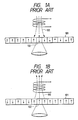
- the direction of vertical magnetization in a recording medium 101 is controlled by the interaction of an external magnetic field 100 and a light spot 102, and recording of information is effected by the utilization of the fact that the vertical magnetization changes in the direction of the external magnetic field only at the location irradiated with the light spot 102.
- recording of information is effected by the utilization of the fact that the vertical magnetization changes in the direction of the external magnetic field only at the location irradiated with the light spot 102.
- erasing of the information must be done in advance for the purpose of making the direction of vertical magnetization in the recording medium definite.
- the external magnetic field of the magneto-optical disc apparatus has the following three kinds of states:
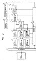
- FIG. 2 of the accompanying drawings shows a schematic block diagram of a magneto-optical disc apparatus according to the prior art and the host controller thereof.
- the reference numeral 10 designates a host controller which is a host apparatus
- the reference numeral 11 denotes an interface circuit which connects the host controller 10 to a drive device
- the reference numeral 13 designates a digital modulating circuit for modulating an information signal in a predetermined modulation system
- the reference numeral 15 denotes a laser driving circuit
- the reference numeral 25 designates an optical head and a driving circuit therefor
- the reference numeral 21 denotes a disc-like magneto-optical recording medium
- the reference numeral 24 designates a spindle motor for rotating the recording medium 21 and a driving circuit therefor
- the reference numeral 22 denotes a coil for producing a bias magnetic field
- the reference numeral 23 designates a bias magnetic field controlling and driving circuit.
- the reference numeral 18 denotes a head amplifier for amplifying a signal from the optical head 25, the reference numeral 16 designates a waveform shaping circuit for shaping the waveform of a signal from the head amplifier 18, the reference numeral 14 denotes a digital demodulating circuit, the reference numeral 17 designates an address confirmation circuit, the reference numeral 20 denotes a magneto-optical disc controller, and the reference numeral 28 designates a track-jump detecting circuit.
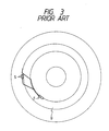
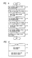
- Figure 4 of the accompanying drawings shows the sequence in which recording of information is effected on the area Q of the recording medium of Figure 3 by the magneto-optical disc apparatus of the construction of Figure 2.
- S designates a recording starting point and E denotes a recording termination point.
- the controller 20 renders the bias magnetic field into the erasing mode by the command of the host controller 10 through the interface circuit 11, and changes over it to the erasing mode in accordance with the command of the bias magnetic field (the step 40 of Figure 4), and thereafter seeks the optical head 25 to the recording starting point S by the command of the host controller 10 (step 41). It erases the data of the area from the S-point to the E-point (step 42), and thereafter renders the bias magnetic field into the recording mode in accordance with the command of the host controller 10 to effect the recording of the data (step 43), whereafter it moves the optical head 25 again to the S-point (step 44), and effects the recording of the data (step 45). After the recording of the data, it renders the bias magnetic field into the reproducing mode with a view to confirm that the data has been recorded properly (step 46), and reproduces the data of the area from the S-point to the E-point (step 47).
- the host controller 10 executes the movement of the optical head 25 after the change-over of the bias magnetic field is completed and therefore, the processing time required for the changeover of the bias magnetic field and the movement of the optical head becomes long.
- the magneto-optical disc controller 20 receives a command from the host controller 10 through the interface circuit 11 and effects the control of the various portions of the magneto-optical disc apparatus (the drive device) such as the movement of the optical head 25 and the change-over of the bias magnetic field.
- the controller 20 controls the optical head driving circuit while detecting from the signal of the track-jump detecting circuit 28 that the optical head has track-jumped. Accordingly, in a controller of ordinary processing ability, control of the other portions cannot be accomplished and therefore, the operation of eliminating the above-noted disadvantage cannot be performed.
- a magneto-optical information recording and erasing method comprising: the step of scanning tracks on a magneto-optical recording medium by a light beam emitted from an optical head while applying a bias magnetic field in a predetermined direction to the medium, and effecting one of the recording and erasing of information; the step of moving said optical head to a desired position across said tracks and at the same time, reversing the direction of application of said bias magnetic field; and the step of scanning the tracks on said medium from said desired position by the light beam emitted from said optical head while applying a bias magnetic field in the reversed direction to said medium, and effecting the other of the recording and erasing of the information.
- Figure 5 is a block diagram schematically showing a construction in which the present invention is applied to a magneto-optical disc apparatus.
- the reference numeral 50 designates a host controller which is a host apparatus
- the reference numeral 52 denotes an interface circuit
- the reference numeral 53 designates a digital modulating circuit for modulating an information signal in a predetermined modulation system
- the reference numeral 54 denotes a laser driving circuit
- the reference numeral 62 designates an optical head and a driving circuit therefor
- the reference numeral 66 denotes a disc-like magneto-optical recording medium
- the reference numeral 65 designates a spindle motor for rotating the recording medium 66 and a driving circuit therefor
- the reference numeral 63 denotes a coil for producing a bias magnetic field
- the reference numeral 64 designates a bias magnetic field controlling and driving circuit
- the reference numeral 67 denotes a ball sensor.
- the reference numeral 60 designates a head amplifier for applifying a signal from the optical head 62
- the reference numeral 56 denotes a waveform shaping circuit for shaping the waveform of a signal from the head amplifier 60
- the reference numeral 55 designates a digital demodulating circuit
- the reference numeral 57 denotes an address confirmation circuit
- the reference numeral 59 designates a magneto-optical disc controller
- the reference numeral 61 denotes an optical head controller for controlling the optical head.
- the optical head controller 61 executes the movement of the optical head 62 while monitoring the signals from a track-jump detecting circuit 58 and the head amplifier 60 by a command from the magneto-optical disc controller 59.
- the host controller 50 gives the magneto-optical disc controller 59 a command for movement of the optical head and a command for change of the external bias magnetic field in the form of a command of code information.
- This command is comprised of an OP code 70, a code 71 indicative of each mode of the aforedescribed bias magnetic field and a code 72 indicative of the direction and amount of movement of the head.
- the magneto-optical disc controller 59 Upon receiving said command, the magneto-optical disc controller 59 gives instructions to the optical head controller 61 as to the amount and direction of movement of the head (step 80) and at the same time, instructs the bias magnetic field driving circuit 64 to change over the bias magnetic field (step 81).
- the optical head controller 61 Upon receiving the instructions for movement of the optical head, the optical head controller 61 monitors and controls the optical head driving circuit 62, the head amplifier 60 and the track-jump detecting circuit 58, and moves the optical head as instructed, and after the completion of the movement, it sends a completion signal to the magneto-optical disc controller 59.
- the magneto-optical disc controller 59 sends the host controller 50 a command execution signal indicative of the completion of the movement of the optical head and the completion of the change-over of the bias magnetic field, thus completing the command.
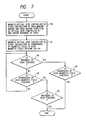
- the host controller 50 renders the bias magnetic field into the erasing mode by the use of the compound command of Figure 6 and moves the head to the S-point (the step 90 of Figure 8). After the completion of the erasing of the data from the S-point to the E-point (step 91), the host controller renders the bias magnetic field into the recording mode to effect the recording of data and moves the head to the S-point (step 92). After the completion of the recording of the data from the S-point to the E-point (step 93), the host controller renders the bias magnetic field into the reproducing mode to effect the reproduction of data with a view to confirm that the data has been recorded properly and moves the head to the S-point (step 94). The data from the S-point to the E-point is reproduced, thus completing the operation.
- the change-over of the magnetic field and the movement of the optical head are executed by the compound command of Figure 6 (the processes of steps 90, 92 and 94) and the magneto-optical disc apparatus of Figure 5 executes the movement of the optical head and the change-over of the bias magnetic field in parallel by the compound command of Figure 6 and therefore, the process time of the steps 90, 92 and 94 of Figure 8 becomes shorter and when the head is moved from the E-point to the S-point and shift is made to the next process (for example, shift is made from the step 92 to the step 93 of Figure 8), the probability of waiting for the rotation of the disc is reduced.
- the host controller 50 uses the compound command of Figure 6 and therefore, when the change-over of the bias magnetic field and the movement of the optical head are to be executed, a command has been output twice in the prior art, whereas in the present invention, a command need only be output once.
- the processing ability of the magneto-optical disc controller 59 is made sufficiently great, it will be possible not to provide the optical head controller 61, but for the magneto-optical disc controller 59 itself to perform also the function of the optical head controller. Generally, however, it is more advantageous in respect of cost to newly provide an optical head controller 61 of the order of 8 bits than to use a CPU having such a great processing ability.
- the magneto-optical recording medium is not limited to the form of a disc, but may be in any form such as a card-like form or a tape-like form.
- the present invention covers all such examples of application without desparting from the scope thereof as defined in the appended claims.
Applications Claiming Priority (2)
| Application Number | Priority Date | Filing Date | Title |
|---|---|---|---|
| JP14059488A JPH01311441A (ja) | 1988-06-09 | 1988-06-09 | 光学的情報記録再生装置 |
| JP140594/88 | 1988-06-09 |
Publications (2)
| Publication Number | Publication Date |
|---|---|
| EP0346063A2 true EP0346063A2 (de) | 1989-12-13 |
| EP0346063A3 EP0346063A3 (de) | 1990-07-18 |
Family
ID=15272326
Family Applications (1)
| Application Number | Title | Priority Date | Filing Date |
|---|---|---|---|
| EP89305681A Withdrawn EP0346063A3 (de) | 1988-06-09 | 1989-06-06 | Magneto-optische Informationsaufzeichnungsmethode und Gerät dafür |
Country Status (2)
| Country | Link |
|---|---|
| EP (1) | EP0346063A3 (de) |
| JP (1) | JPH01311441A (de) |
Cited By (1)
| Publication number | Priority date | Publication date | Assignee | Title |
|---|---|---|---|---|
| EP0568009A3 (de) * | 1992-04-28 | 1995-05-24 | Sony Corp | Aufzeichnungsstartverfahren für eine magneto-optische Plattenaufzeichnungsvorrichtung. |
Family Cites Families (3)
| Publication number | Priority date | Publication date | Assignee | Title |
|---|---|---|---|---|
| JPH0619863B2 (ja) * | 1984-06-13 | 1994-03-16 | 株式会社日立製作所 | 光磁気情報記憶方法及び装置 |
| US4701894A (en) * | 1986-03-28 | 1987-10-20 | Rca Corporation | Magnetic biasing apparatus for magneto-optic recording including a magnetic circuit |
| JPH0687323B2 (ja) * | 1986-04-10 | 1994-11-02 | キヤノン株式会社 | 光磁気記録再生装置 |
-
1988
- 1988-06-09 JP JP14059488A patent/JPH01311441A/ja active Pending
-
1989
- 1989-06-06 EP EP89305681A patent/EP0346063A3/de not_active Withdrawn
Cited By (2)
| Publication number | Priority date | Publication date | Assignee | Title |
|---|---|---|---|---|
| EP0568009A3 (de) * | 1992-04-28 | 1995-05-24 | Sony Corp | Aufzeichnungsstartverfahren für eine magneto-optische Plattenaufzeichnungsvorrichtung. |
| US5495455A (en) * | 1992-04-28 | 1996-02-27 | Sony Corporation | Magneto-optical disk recording and reading apparatus and method wherein the recording head is controlled in the radial direction of the disk to a desired position |
Also Published As
| Publication number | Publication date |
|---|---|
| JPH01311441A (ja) | 1989-12-15 |
| EP0346063A3 (de) | 1990-07-18 |
Similar Documents
| Publication | Publication Date | Title |
|---|---|---|
| US5010534A (en) | Optical information recording-reproducing apparatus | |
| US5521893A (en) | Data recording apparatus | |
| EP0346063A2 (de) | Magneto-optische Informationsaufzeichnungsmethode und Gerät dafür | |
| US5640378A (en) | Disc recording apparatus for recording data in units of a full cluster | |
| US5144504A (en) | Method of controlling positioning of magnetic head of disk drive unit and disk drive unit executing same | |
| EP0656626B1 (de) | Informationsaufzeichnungs/-wiedergabeverfahren | |
| JPH0711849B2 (ja) | フロツピ−デイスク装置のデ−タ記録制御装置 | |
| US5293361A (en) | Information processing method and apparatus therefor in which an erasing device is driven for a period longer than a necessary period | |
| US5452273A (en) | Optical recording method and apparatus therefor | |
| JPS61240453A (ja) | 光磁気デイスク装置 | |
| EP0263663A2 (de) | Informations-Verarbeitungsgerät, in welchen Löschmittel länger als die nötige Periode angetrieben sind | |
| JPS59140634A (ja) | 光デイスク装置の記録方式 | |
| JP2746531B2 (ja) | 情報処理システム | |
| EP0479521B1 (de) | Betriebszustandsteuerung für Datenaufzeichnungsgerät mit Aufzeichnungsplatte | |
| JPH0612562B2 (ja) | 磁気記録再生装置 | |
| JPH0210544A (ja) | 光磁気記憶装置 | |
| JP2793326B2 (ja) | 情報記録再生方法 | |
| JPH0721891B2 (ja) | 情報記録再生装置 | |
| JPH03150742A (ja) | 情報記録再生装置 | |
| JPS63102054A (ja) | 光学式情報記録再生装置 | |
| JPS59140605A (ja) | 光磁気記録装置の情報消去方法 | |
| JPH0268782A (ja) | ヘッド位置決め制御方法 | |
| JPS6122453A (ja) | 光情報記録再生装置 | |
| JP2001006256A (ja) | 光ディスク装置 | |
| JPH0793890A (ja) | 情報記録再生装置 |
Legal Events
| Date | Code | Title | Description |
|---|---|---|---|
| PUAI | Public reference made under article 153(3) epc to a published international application that has entered the european phase |
Free format text: ORIGINAL CODE: 0009012 |
|
| AK | Designated contracting states |
Kind code of ref document: A2 Designated state(s): DE FR GB |
|
| PUAL | Search report despatched |
Free format text: ORIGINAL CODE: 0009013 |
|
| AK | Designated contracting states |
Kind code of ref document: A3 Designated state(s): DE FR GB |
|
| 17P | Request for examination filed |
Effective date: 19901210 |
|
| 17Q | First examination report despatched |
Effective date: 19930301 |
|
| STAA | Information on the status of an ep patent application or granted ep patent |
Free format text: STATUS: THE APPLICATION IS DEEMED TO BE WITHDRAWN |
|
| 18D | Application deemed to be withdrawn |
Effective date: 19930914 |