EP0346890A1 - Ultraschallgerät zur Messung der Blutstromgeschwindigkeit - Google Patents
Ultraschallgerät zur Messung der Blutstromgeschwindigkeit Download PDFInfo
- Publication number
- EP0346890A1 EP0346890A1 EP89110830A EP89110830A EP0346890A1 EP 0346890 A1 EP0346890 A1 EP 0346890A1 EP 89110830 A EP89110830 A EP 89110830A EP 89110830 A EP89110830 A EP 89110830A EP 0346890 A1 EP0346890 A1 EP 0346890A1
- Authority
- EP
- European Patent Office
- Prior art keywords
- signal
- signals
- pair
- doppler
- detection
- Prior art date
- Legal status (The legal status is an assumption and is not a legal conclusion. Google has not performed a legal analysis and makes no representation as to the accuracy of the status listed.)
- Granted
Links
Images

Classifications
-
- G—PHYSICS
- G01—MEASURING; TESTING
- G01S—RADIO DIRECTION-FINDING; RADIO NAVIGATION; DETERMINING DISTANCE OR VELOCITY BY USE OF RADIO WAVES; LOCATING OR PRESENCE-DETECTING BY USE OF THE REFLECTION OR RERADIATION OF RADIO WAVES; ANALOGOUS ARRANGEMENTS USING OTHER WAVES
- G01S15/00—Systems using the reflection or reradiation of acoustic waves, e.g. sonar systems
- G01S15/02—Systems using the reflection or reradiation of acoustic waves, e.g. sonar systems using reflection of acoustic waves
- G01S15/50—Systems of measurement, based on relative movement of the target
- G01S15/52—Discriminating between fixed and moving objects or between objects moving at different speeds
-
- A—HUMAN NECESSITIES
- A61—MEDICAL OR VETERINARY SCIENCE; HYGIENE
- A61B—DIAGNOSIS; SURGERY; IDENTIFICATION
- A61B8/00—Diagnosis using ultrasonic, sonic or infrasonic waves
- A61B8/06—Measuring blood flow
-
- G—PHYSICS
- G01—MEASURING; TESTING
- G01S—RADIO DIRECTION-FINDING; RADIO NAVIGATION; DETERMINING DISTANCE OR VELOCITY BY USE OF RADIO WAVES; LOCATING OR PRESENCE-DETECTING BY USE OF THE REFLECTION OR RERADIATION OF RADIO WAVES; ANALOGOUS ARRANGEMENTS USING OTHER WAVES
- G01S15/00—Systems using the reflection or reradiation of acoustic waves, e.g. sonar systems
- G01S15/02—Systems using the reflection or reradiation of acoustic waves, e.g. sonar systems using reflection of acoustic waves
- G01S15/50—Systems of measurement, based on relative movement of the target
- G01S15/58—Velocity or trajectory determination systems; Sense-of-movement determination systems
- G01S15/586—Velocity or trajectory determination systems; Sense-of-movement determination systems using transmission of continuous unmodulated waves, amplitude-, frequency-, or phase-modulated waves and based upon the Doppler effect resulting from movement of targets
Definitions
- This invention relates to an ultrasonic blood velocity detector using the Doppler shifts.
- Blood velocity can be detected by measuring the Doppler shifts in frequency imparted to ultrasound by reflection from moving red blood cells.
- An ultrasonic blood velocity detector of this invention comprises an ultrasonic probe emitting ultrasonic wave into an examined body and converting echoes of the emitted ultrasonic wave into an echo signal.
- the echo signal is processed into a detection signal through phase detection.
- a first Doppler signal and a second Doppler signal are derived from the detection signal.
- the first Doppler signal represents a flow of blood.
- the second Doppler signal mainly contains clutter components. A difference in phase between the first and second Doppler signals is calculated.
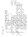
- a pulse-type ultrasonic blood velocity detector includes a clock generator 1 which outputs a clock signal CK to an orthogonal (quadrature) signal generator 2, a trigger signal generator 3, and gate signal generators 4a and 4b.
- the orthogonal signal generator 2 derives a pair of orthogonal or quadrature reference signals Rx and Ry from the clock signal CK through a frequency division process and a phase shift process.
- the reference signals Rx and Ry are orthogonal to each other and have a phase difference of 90°.
- the trigger signal generator 3 derives a trigger pulse signal Tg from the clock signal CK through a frequency division process.
- the trigger signal Tg is fed to the gate signal generators 4a and 4b.
- the gate signal generator 4a counts pulses of the clock signal CK and outputs a gate signal GATE1 at a predetermined time measured from a reference timing determined by the trigger signal Tg.
- the gate signal generator 4b outputs a gate signal GATE2 at a predetermined time measured from the reference timing.
- the trigger signal Tg is also fed to a transmitter 5.
- the transmitter 5 generates a drive pulse signal synchronous with the trigger signal Tg.
- the drive pulse signal is outputted from the transmitter 5 to an ultrasonic probe 6.
- the ultrasonic probe 6 converts the drive pulse signal into pulses of beam of corresponding ultrasonic wave and emits the ultrasonic beam pulses into an examined body 16. Echoes of the ultrasonic beam pulses are generated within the body 16 and portions of the echoes return to the ultrasonic probe 6.
- the ultrasonic probe 6 converts the ultrasonic echoes into a corresponding echo signal or received signal.
- the echo signal is fed from the ultrasonic probe 6 to mixers 8a and 8b via an amplifier 7.
- the mixer 8a processes the received signal into a first detection signal through orthogonal detection or phase detection by use of the reference signal Rx outputted from the orthogonal signal generator 2.
- the mixer 8b processes the received signal into a second detection signal through orthogonal detection or phase detection by use of the reference signal Ry outputted from the orthogonal signal generator 2.
- An integrator 9a integrates the first detection signal during a period determined by the gate signal GATE1.
- An integrator 9b integrates the second detection signal during the period determined by the gate signal GATE1.
- the integrators 9a and 9b output a pair of first orthogonal Doppler signals Vdx1 and Vdy1 respectively.
- An integrator 9c integrates the first detection signal during a period determined by the gate signal GATE2.
- An integrator 9d integrates the second detection signal during the period determined by the gate signal GATE2.
- the integrators 9c and 9d output a pair of second orthogonal Doppler signals Vdx2 and Vdy2 respectively.
- Sample-and-hold circuits 10a and 10b sample the first Doppler signals Vdx1 and Vdy1 respectively at a timing determined by the gate signal GATE1 and hold the sampled signals Vdx1 and Vdy1 until the subsequent sampling.
- Sample-and-hold circuits 10c and 10d sample the second Doppler signals Vdx2 and Vdy2 respectively at a timing determined by the gate signal GATE2 and hold the sampled signals Vdx2 and Vdy2 until the subsequent sampling.
- a phase difference calculator 11 determines a phase difference between the first Doppler signals Vdx1 and Vdy1 and the second Doppler signals Vdx2 and Vdy2 outputted from the sample-and-hold circuits 10a-10d.
- the phase difference calculator 11 derives a pair of orthogonal final Doppler signals Vdx and Vdy from the first and second Doppler signals through the phase difference calculation.
- the final Doppler signals Vdx and Vdy are fed from the phase difference calculator 11 to analog-to-digital converters 13a and 13b via high pass filters 12a and 12b respectively.
- the high pass filters 12a and 12b remove clutter components from the Doppler signals Vdx and Vdy.
- the devices 13a and 13b convert the Doppler signals Vdx and Vdy into corresponding digital Doppler signals applied to a frequency analyzer 14.
- the device 14 analyzes the frequency of the digital Doppler signals.
- a display 15 indicates a result of the frequency analyzation of the digital Doppler signals which is performed by the frequency analyzer 14.
- the ultrasonic blood velocity detector operates as follows.
- the clock generator 1 outputs the clock signal CK.
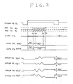
- the orthogonal signal generator 2 derives a pair of the orthogonal reference signals Rx and Ry from the clock signal CK through a frequency division process and a phase shift process. As shown in Fig. 2, the reference signals Rx and Ry are 90° out of phase from each other.
- the trigger signal generator 3 derives the trigger pulse signal Tg from the clock signal CK through a frequency division process. As shown in Fig. 2, the trigger signal Tg has a constant period.
- the gate signal generator 4a starts to count pulses of the clock signal CK in response to the trigger signal Tg and outputs the gate signal GATE1 including a pulse synchronous with the trigger signal Tg.
- the gate signal pulse GATE1 starts at a moment Ta1 which follows the trigger pulse Tg by a predetermined delay time Td1.
- the gate signal pulse GATE1 lasts for a predetermined interval Tw1 and terminates at a moment Ta2.
- the gate signal generator 4b starts to count pulses of the clock signal CK in response to the trigger signal Tg and outputs the gate signal GATE2 including a pulse synchronous with the trigger pulse Tg.
- the gate signal generator 4b starts to count pulses of the clock signal CK in response to the trigger signal Tg and outputs the gate signal GATE2 including a pulse synchronous with the trigger pulse Tg.
- the gate signal pulse GATE2 starts at a moment Tb1 which follows the trigger pulse Tg by a predetermined delay time Td2.
- the moment Tb1 of the start of the gate signal pulse GATE2 is close to the moment Ta1 of the start of the gate signal pulse GATE1.
- the gate signal pulse GATE2 lasts for a predetermined interval Tw2 and terminates at a moment Tb2.
- the moment Tb2 of the termination of the gate signal pulse GATE2 is close to the moment Ta2 of the termination of the gate signal pulse GATE1.
- the transmitter 5 generates the drive pulse signal in response to the trigger signal Tg.
- the drive pulse signal is outputted to the ultrasonic probe 6 in contact with the examined body 16.
- the ultrasonic probe 6 converts the drive pulse signal into pulses of a beam of corresponding ultrasonic wave and emits the ultrasonic beam pulses into the examined body 16. Echoes of the ultrasonic beam pulses are generated at internal portions of the examined body 16 such as organs 19, a blood vessel 17, and blood 18 within the blood vessel 17. Parts of the echoes return to the ultrasonic probe 6.
- the ultrasonic probe 6 converts the ultrasonic echoes into the corresponding echo signal or received signal.
- the echo signal includes echo components which occur at respective moments dependent upon the distances from the surface of the examined body 16 to the positions of the generation of the corresponding ultrasonic echoes.
- the echo components which result from the ultrasonic echoes generated at the front walls and the rear walls of the blood vessel 17 are present at the moments Ta1 and Ta2 respectively while the echo components which result from the ultrasonic echoes generated by the blood 18 are present for the interval between the moments Ta1 and Ta2.
- the echo components which result from the ultrasonic echoes generated at the other portions of the examined body 16 are present during a period except the interval between the moments Ta1 and Ta2.
- the duration Tw1 of the gate signal pulse GATE1 is equal to or shorter than the duration Tw2 of the gate signal pulse GATE2.
- the gate signal pulse GATE1 is designed to last for the period during which the echo signal mainly corresponds to the ultrasonic echoes generated by the blood 18.
- the gate signal pulse GATE2 is designed to last for the period during which the echo signal corresponds to the ultrasonic echoes generated by the blood 18, the blood vessel 17, and also the organs 19 surrounding the blood vessel 17.
- the echo signal or received signal is fed from the ultrasonic probe 6 to the mixers 8a and 8b via the amplifier 7.
- the mixer 8a mixes the echo signal and the reference signal Rx and specifically processes the echo signal into the first detection signal through orthogonal detection or phase detection by use of the reference signal Rx.
- the mixer 8b mixes the echo signal and the reference signal Ry and specifically processes the echo signal into the second detection signal through orthogonal detection or phase detection by use of the reference signal Ry.
- the integrator 9a integrates the first detection signal during the interval corresponding to the duration Tw1 of the gate signal pulse GATE1.
- the integrator 9b integrates the second detection signal during the interval corresponding to the duration Tw1 of the gate signal pulse GATE1.
- the integrators 9a and 9b output a pair of the first orthogonal Doppler signals Vdx1 and Vdy1 which represent the flow of the blood 18.
- One example of the waveforms of the first Doppler signals Vdx1 and Vdy1 is shown in Fig. 2.
- the integrator 9c integrates the first detection signal during the interval corresponding to the duration Tw2 of the gate signal pulse GATE2.
- the integrator 9d integrates the second detection signal during the interval corresponding to the duration Tw2 of the gate signal pulse GATE2.
- the integrators 9c and 9d output a pair of the second orthogonal Doppler signals Vdx2 and Vdy2 which represent the flow of the blood 18 and also the motion of the organs 19 surrounding the blood vessel 17.
- One example of the waveforms of the second Doppler signals Vdx2 and Vdy2 is shown in Fig. 2.
- the sample-and-hold circuits 10a and 10b sample the first Doppler signals Vdx1 and Vdy1 at the moment Ta2 determined by the gate signal GATE1 and hold the sampled signals Vdx1 and Vdy1 until the subsequent sampling moment.
- the sample-and-hold circuits 10c and 10d sample the second Doppler signals Vdx2 and Vdy2 at the moment Tb2 determined by the gate signal GATE2 and hold the sampled signals Vdx2 and Vdy2 until the subsequent sampling moment.
- Doppler shift frequency fdo is expressed by the following equation (1).
- V1 denotes the velocity of the blood 18
- V2 denotes the velocity of the organs 19
- the character C denotes the speed of sound in the ultrasonic propagation medium
- the character fc denotes the frequency of the ultrasonic wave
- the character ⁇ denotes the angle between the direction of the travel of the ultrasonic wave and the direction of the flow of the blood 18.
- the Doppler shift frequency fdo is decomposed into an accurate signal part fd1 and a clutter part fd2 as expressed in the following equation (2).
- fdo fd1 + fd2 (2) where the component fd1 results from the flow of the blood 18 and the component fd2 results from the motion of the organs 19.
- the first Doppler signals Vdx1 and Vdy1 are expressed by the following equations (3) and (4) including the accurate signal component fd1 and the clutter component fd2.
- Vdx1 A1 ⁇ cos ⁇ 2 ⁇ (fd1+fd2) ⁇ t ⁇ (3)
- Vdy1 A1 ⁇ sin ⁇ 2 ⁇ (fd1+fd2) ⁇ t ⁇ (4) where the character A1 denotes a constant representing the amplitude.
- the second Doppler signals Vdx2 and Vdy2 held by the sample-and-hold circuits 10C and 10d mainly include clutter components caused by the motion of the organs 19.
- the Doppler shift frequency fd2 related to the motion of the organs 19 is expressed by the following equation (5).
- fd2 (2 ⁇ V2/C ⁇ fc ⁇ cos ⁇ (5) where the character V2 denotes the velocity of the organs 19 and the character ⁇ denotes the angle between the direction of the travel of the ultrasonic wave and the direction of the motion of the organs 19.
- the second Doppler signals Vdx2 and Vdy2 are expressed by the following equations (6) and (7) as in the case of the first Doppler signals Vdx1 and Vdy1.
- Vdx2 A2 ⁇ cos(2 ⁇ fd2 ⁇ t ⁇ (6)
- Vdy2 A2 ⁇ sin(2 ⁇ fd2 ⁇ t ⁇ (7) where the character A2 denotes a constant representing the amplitude.
- the accurate signal component fd1 can be derived by determining the phase difference between the first Doppler signals Vdx1 and Vdy1 and the second Doppler signals Vdx2 and Vdy2. This process is executed by the phase difference calculator 11.
- the phase difference calculator 11 determines a phase difference between the first Doppler signals Vdx1 and Vdy1 and the second Doppler signals Vdx2 and Vdy2 outputted from the sample-and-hold circuits 10a-10d.
- the phase difference calculator 11 derives a pair of orthogonal final Doppler signals Vdx and Vdy from the first and second Doppler signals through the phase difference calculation.
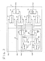
- the phase difference calculator 11 includes an AGC circuit 20 in which squaring devices 20a and 20b square the second Doppler signals Vdx2 and Vdy2 respectively.
- the output signals from the squaring devices 20a and 20b are added by an adder 20c.
- a square root device 20d derives the amplitude A2 by calculating the square root of the output signal from the adder 20c.
- Dividers 20e and 20f divides the second Doppler signals Vdx2 and Vdy2 by the amplitude A2 calculated by the square root device 20d.
- the output signals Vdx2/A2 and Vdy2/A2 are expressed by the following equations (8) and (9).
- Vdx2/A2 cos(2 ⁇ fd2 ⁇ t ⁇ (8)
- Vdy2/A2 sin(2 ⁇ fd2 ⁇ t ⁇ (9)
- the phase difference calculator 11 also includes multipliers 21, 22, 23, and 24.
- the multiplier 21 calculates the product of the first Doppler signal Vdx1 and the output signal Vdx2/A2 from the divider 20e.
- the multiplier 22 calculates the product of the first Doppler signal Vdy1 and the output signal Vdy2/A2 from the divider 20f.
- the multiplier 23 calculates the product of the first Doppler signal Vdx1 and the output signal Vdy2/A2 from the divider 20f.
- the multiplier 24 calculates the product of the first Doppler signal Vdy1 and the output signal Vdx2/A2 from the divider 20e.
- An adder 25 derives the final Doppler signal Vdx by adding the output signals from the multipliers 21 and 22.
- a subtracter 26 derives the final Doppler signal Vdy by subtracting the output signal of the multiplier 24 from the output signal from the multiplier 23.
- the final Doppler signals Vdx and Vdy are expressed by the following equations (10) and (11).
- Vdx A1 ⁇ cos(2 ⁇ fd1 ⁇ t ⁇ (10)
- Vdy A1 ⁇ sin(2 ⁇ fd1 ⁇ t ⁇ (11)
- the final Doppler signals Vdx and Vdy are substantially free from the clutter components represented by the factor fd2.
- the final Doppler signals Vdx and Vdy are fed from the phase difference calculator 11 to the analog-to-digital converters 13a and 13b via the high pass filters 12a and 12b respectively.
- the high pass filters 12a and 12b further remove clutter components from the Doppler signals Vdx and Vdy.
- the devices 13a and 13b convert the Doppler signals Vdx and Vdy into corresponding digital Doppler signals applied to the frequency analyzer 14.
- the device 14 analyzes the frequency of the digital Doppler signals.
- the display 15 indicates a result of the frequency analyzation of the digital Doppler signals which is performed by the frequency analyzer 14.
- a CW-type (continuous wave type) ultrasonic blood velocity detector includes a clock generator 31 which outputs a clock signal CK to an orthogonal signal generator 32 and a transmitter 33.
- the orthogonal signal generator 32 derives a pair of orthogonal reference signals Rx and Ry from the clock signal CK through a frequency division process and a phase shift process.
- the reference signals Rx and Ry are orthogonal to each other and have a phase difference of 90°.
- the transmitter 33 generates a continuous drive signal in response to the clock signal CK.
- the drive signal is outputted from the transmitter 33 to an ultrasonic probe 34.
- the ultrasonic probe 34 converts the drive signal into a continuous beam of corresponding ultrasonic wave and emits the ultrasonic beam into an examined body 16. Echoes of the ultrasonic beam are generated within the body 16 and portions of the echoes return to the ultrasonic probe 34.
- the ultrasonic probe 34 converts the ultrasonic echoes into a corresponding echo signal or received signal.
- the echo signal is fed from the ultrasonic probe 34 to mixers 37a and 37b via a notch filter 35 and an amplifier 36.
- the notch filter 35 removes frequency-unshifted components from the echo signal.
- the mixer 37a processes the echo signal into a first detection signal Vdx1 through orthogonal detection or phase detection by use of the reference signal Rx outputted from the orthogonal signal generator 32.
- the mixer 37b processes the echo signal into a second detection signal Vdy1 through orthogonal detection or phase detection by use of the reference signal Ry outputted from the orthogonal signal generator 32.
- a low pass filter 38a derives a first clutter signal Vdx2 by extracting low-frequency clutter components from the first detection signal Vdx1 outputted from the mixer 37a.
- a second low pass filter 38a derives a second clutter signal Vdy2 by extracting low-frequency clutter components from the second detection signal Vdy1 outputted from the mixer 37b.
- a phase difference calculator 39 determines a phase difference between the detection signals Vdx1 and Vdy1 and the clutter signals Vdx2 and Vdy2 outputted from the devices 37a, 37b, 38a, and 38b.
- the phase difference calculator 11 derives a pair of orthogonal Doppler signals Vdx and Vdy from the detection signals Vdx1 and Vdy1 and the clutter signals Vdx2 and Vdy2 as in the embodiment of Figs. 1-3.
- the Doppler signals Vdx and Vdy are fed from the phase difference calculator 39 to analog-to-digital converters 41a and 41b via high pass filters 40a and 40b respectively.
- the high pass filters 40a and 40b remove clutter components from the Doppler signals Vdx and Vdy.
- the devices 41a and 41b convert the Doppler signals Vdx and Vdy into corresponding digital Doppler signals applied to a frequency analyzer 42.
- the device 42 analyzes the frequency of the digital Doppler signals.
- a display 43 indicates a result of the frequency analyzation of the digital Doppler signals which is performed by the frequency analyzer 42.
- the ultrasonic blood velocity detector operates as follows.
- the clock generator 1 outputs the clock signal CK which has a constant frequency.
- the orthogonal signal generator 2 derives a pair of the orthogonal reference signals Rx and Ry from the clock signal CK through a frequency division process and a phase shift process.
- the reference signals Rx and Ry have a predetermined frequency fc and are 90° out of phase from each other.
- the transmitter 33 derives the continuous drive signal by frequency-dividing the clock signal CK.
- the drive signal also has the predetermined frequency fc.
- the drive signal is outputted to the ultrasonic probe 34 in contact with the examined body 16.
- the ultrasonic probe 34 converts the drive signal into a continuous beam of corresponding ultrasonic wave and emits the ultrasonic beam into the examined body 16. Echoes of the ultrasonic beam are generated at internal portions of the examined body 16 such as organs 19, a blood vessel 17, and blood 18 within the blood vessel 17. Parts of the echoes return to the ultrasonic probe 34.
- the ultrasonic probe 34 converts the ultrasonic echoes into the corresponding echo signal or received signal.
- the notch filter 35 removes frequency-unshifted components or strong clutter components from the echo signal.
- the mixer 37a mixes the echo signal and the reference signal Rx and specifically processes the echo signal into the first detection signal (Doppler signal) Vdx1 through orthogonal detection or phase detection by use of the reference signal Rx.
- the mixer 37b mixes the echo signal and the reference signal Ry and specifically processes the echo signal into the second detection signal (Doppler signal) Vdy1 through orthogonal detection or phase detection by use of the reference signal Ry.
- the detection signals Vdx1 and Vdy1 are expressed by the previously-mentioned equations (3) and (4).
- the clutter signals Vdx2 and Vdy2 are extracted from the detection signals Vdx1 and Vdy1 by the low pass filters 38a and 38b.
- the clutter signals Vdx2 and Vdy2 are expressed by the previously-mentioned equations (6) and (7).
- the phase difference calculator 39 derives the Doppler signals Vdx and Vdy from the detection signals Vdx1 and Vdy1 and the clutter signals Vdx2 and Vdy2 as in the embodiment of Figs. 1-3.
- the Doppler signals Vdx and Vdy are expressed by the previously-mentioned equations (10) and (11).
- the Doppler signals Vdx and Vdy are fed from the phase difference calculator 39 to the analog-to-digital converters 41a and 41b via the high pass filters 40a and 40b respectively.
- the high pass filters 40a and 40b further remove clutter components from the Doppler signals Vdx and Vdy.
- the devices 41a and 41b convert the Doppler signals Vdx and Vdy into corresponding digital Doppler signals applied to the frequency analyzer 42.
- the device 42 analyzes the frequency of the digital Doppler signals.
- the display 43 indicates a result of the frequency analyzation of the digital Doppler signals which is performed by the frequency analyzer 42.
- An ultrasonic blood velocity detector comprises an ultrasonic probe emitting ultrasonic wave into an examined body and converting echoes of the emitted ultrasonic wave into an echo signal.
- the echo signal is processed into a detection signal through phase detection.
- a first Doppler signal and a second Doppler signal are derived from the detection signal.
- the first Doppler signal represents a flow of blood.
- the second Doppler signal mainly contains clutter components. A difference in phase between the first and second Doppler signals is calculated.
Landscapes
- Engineering & Computer Science (AREA)
- Physics & Mathematics (AREA)
- Radar, Positioning & Navigation (AREA)
- Remote Sensing (AREA)
- Health & Medical Sciences (AREA)
- Life Sciences & Earth Sciences (AREA)
- Acoustics & Sound (AREA)
- Computer Networks & Wireless Communication (AREA)
- General Physics & Mathematics (AREA)
- Pathology (AREA)
- Medical Informatics (AREA)
- Nuclear Medicine, Radiotherapy & Molecular Imaging (AREA)
- Hematology (AREA)
- Radiology & Medical Imaging (AREA)
- Biomedical Technology (AREA)
- Heart & Thoracic Surgery (AREA)
- Biophysics (AREA)
- Molecular Biology (AREA)
- Surgery (AREA)
- Animal Behavior & Ethology (AREA)
- General Health & Medical Sciences (AREA)
- Public Health (AREA)
- Veterinary Medicine (AREA)
- Ultra Sonic Daignosis Equipment (AREA)
Applications Claiming Priority (2)
| Application Number | Priority Date | Filing Date | Title |
|---|---|---|---|
| JP147460/88 | 1988-06-15 | ||
| JP63147460A JP2553635B2 (ja) | 1988-06-15 | 1988-06-15 | 超音波ドップラ血流計 |
Publications (2)
| Publication Number | Publication Date |
|---|---|
| EP0346890A1 true EP0346890A1 (de) | 1989-12-20 |
| EP0346890B1 EP0346890B1 (de) | 1994-01-19 |
Family
ID=15430870
Family Applications (1)
| Application Number | Title | Priority Date | Filing Date |
|---|---|---|---|
| EP89110830A Expired - Lifetime EP0346890B1 (de) | 1988-06-15 | 1989-06-14 | Ultraschallgerät zur Messung der Blutstromgeschwindigkeit |
Country Status (4)
| Country | Link |
|---|---|
| US (1) | US5031628A (de) |
| EP (1) | EP0346890B1 (de) |
| JP (1) | JP2553635B2 (de) |
| DE (1) | DE68912414T2 (de) |
Cited By (3)
| Publication number | Priority date | Publication date | Assignee | Title |
|---|---|---|---|---|
| EP0361945A3 (de) * | 1988-09-30 | 1991-04-24 | Shigeo Ohtsuki | Messung der Dopplergeschwindigkeit |
| DE4134724A1 (de) * | 1990-10-24 | 1992-05-14 | Hitachi Medical Corp | Einrichtung zur farbigen stroemungsaufzeichnung mit ultraschall |
| EP0582462A3 (de) * | 1992-08-03 | 1995-01-04 | Olympus Optical Co | Ultraschalldiagnosegerät. |
Families Citing this family (5)
| Publication number | Priority date | Publication date | Assignee | Title |
|---|---|---|---|---|
| JP2772045B2 (ja) * | 1989-07-06 | 1998-07-02 | 株式会社東芝 | 超音波診断装置 |
| US5226328A (en) * | 1989-11-17 | 1993-07-13 | Ads Environmental Services, Inc. | Velocity measurement system |
| FR2655260A1 (fr) * | 1989-12-01 | 1991-06-07 | Philips Electronique Lab | Dispositif de mesure et de visualisation par echographie ultrasonore de parametres physiologiques d'un ecoulement sanguin. |
| US5315880A (en) * | 1992-08-13 | 1994-05-31 | Henry Filters, Inc. | Method for measuring fluid velocity by measuring the Doppler frequency shift or microwave signals |
| US20090240148A1 (en) * | 2008-03-19 | 2009-09-24 | University Of Southern California | Ultrasonic apparatus and method for real-time simultaneous therapy and diagnosis |
Citations (4)
| Publication number | Priority date | Publication date | Assignee | Title |
|---|---|---|---|---|
| US4554926A (en) * | 1981-10-23 | 1985-11-26 | Tokyo Shibaura Denki Kabushiki Kaisha | Ultrasonic pulse Doppler blood flow meter with provision to create ultrasonic test waves which, when reflected from a stationary object, result in echoes similar to those produced by a moving object |
| EP0166392A2 (de) * | 1984-06-23 | 1986-01-02 | Aloka Co. Ltd. | Frequenzumsetzer eines Dopplersignals |
| EP0202920A2 (de) * | 1985-05-20 | 1986-11-26 | Matsushita Electric Industrial Co., Ltd. | Blutgeschwindigkeitsmesser nach dem Ultraschall-Doppler-Prinzip |
| EP0217953A1 (de) * | 1984-07-20 | 1987-04-15 | Yokogawa Medical Systems, Ltd | Analysevorrichtung für dopplersignal |
Family Cites Families (2)
| Publication number | Priority date | Publication date | Assignee | Title |
|---|---|---|---|---|
| JPS5897347A (ja) * | 1981-12-03 | 1983-06-09 | 株式会社東芝 | 超音波診断装置 |
| JPH0693890B2 (ja) * | 1985-04-30 | 1994-11-24 | 株式会社東芝 | 超音波診断装置 |
-
1988
- 1988-06-15 JP JP63147460A patent/JP2553635B2/ja not_active Expired - Fee Related
-
1989
- 1989-06-12 US US07/364,727 patent/US5031628A/en not_active Expired - Lifetime
- 1989-06-14 DE DE89110830T patent/DE68912414T2/de not_active Expired - Fee Related
- 1989-06-14 EP EP89110830A patent/EP0346890B1/de not_active Expired - Lifetime
Patent Citations (4)
| Publication number | Priority date | Publication date | Assignee | Title |
|---|---|---|---|---|
| US4554926A (en) * | 1981-10-23 | 1985-11-26 | Tokyo Shibaura Denki Kabushiki Kaisha | Ultrasonic pulse Doppler blood flow meter with provision to create ultrasonic test waves which, when reflected from a stationary object, result in echoes similar to those produced by a moving object |
| EP0166392A2 (de) * | 1984-06-23 | 1986-01-02 | Aloka Co. Ltd. | Frequenzumsetzer eines Dopplersignals |
| EP0217953A1 (de) * | 1984-07-20 | 1987-04-15 | Yokogawa Medical Systems, Ltd | Analysevorrichtung für dopplersignal |
| EP0202920A2 (de) * | 1985-05-20 | 1986-11-26 | Matsushita Electric Industrial Co., Ltd. | Blutgeschwindigkeitsmesser nach dem Ultraschall-Doppler-Prinzip |
Non-Patent Citations (1)
| Title |
|---|
| "New ultrasonic diagnostic technique", CLINICAL ULTRASONIC WAVE SERIES 9, 1984, pages 86 |
Cited By (6)
| Publication number | Priority date | Publication date | Assignee | Title |
|---|---|---|---|---|
| EP0361945A3 (de) * | 1988-09-30 | 1991-04-24 | Shigeo Ohtsuki | Messung der Dopplergeschwindigkeit |
| DE4134724A1 (de) * | 1990-10-24 | 1992-05-14 | Hitachi Medical Corp | Einrichtung zur farbigen stroemungsaufzeichnung mit ultraschall |
| US5246006A (en) * | 1990-10-24 | 1993-09-21 | Hitachi Medical Corporation | Apparatus for ultrasonic color flow mapping |
| EP0582462A3 (de) * | 1992-08-03 | 1995-01-04 | Olympus Optical Co | Ultraschalldiagnosegerät. |
| US5431169A (en) * | 1992-08-03 | 1995-07-11 | Olympus Optical Co., Ltd. | Ultrasonic diagnosing apparatus |
| EP0885593A3 (de) * | 1992-08-03 | 1999-03-10 | Olympus Optical Co., Ltd. | Ultraschalldiagnosegerät |
Also Published As
| Publication number | Publication date |
|---|---|
| JP2553635B2 (ja) | 1996-11-13 |
| US5031628A (en) | 1991-07-16 |
| DE68912414T2 (de) | 1994-05-11 |
| EP0346890B1 (de) | 1994-01-19 |
| DE68912414D1 (de) | 1994-03-03 |
| JPH01314552A (ja) | 1989-12-19 |
Similar Documents
| Publication | Publication Date | Title |
|---|---|---|
| Brandestini | Topoflow-A digital full range Doppler velocity meter | |
| US5177691A (en) | Measuring velocity of a target by Doppler shift, using improvements in calculating discrete Fourier transform | |
| US4542657A (en) | Time domain technique to determine mean frequency | |
| US4944189A (en) | Ultrasonic speckle velocity measurement method and apparatus | |
| JPH0331455B2 (de) | ||
| US5031628A (en) | Ultrasonic blood velocity detector | |
| EP0345960B1 (de) | Doppler-Ultraschallgerät zur Bestimmung von Blutströmungsgeschwindigkeiten | |
| JPH03162837A (ja) | 医用超音波装置 | |
| JPS62117535A (ja) | 超音波ドプラ装置 | |
| JP2640657B2 (ja) | 超音波ドプラ計 | |
| JP3061430B2 (ja) | 速度測定装置 | |
| JP3281435B2 (ja) | 超音波ドプラ診断装置 | |
| EP0512837B1 (de) | Ultraschall-Doppler-Abbildungsgerät | |
| JP2953083B2 (ja) | 高限界速パルスドプラ計測装置 | |
| EP0474867B1 (de) | Verfahren zur verarbeitung von dopplersignalen | |
| JP2563656B2 (ja) | 超音波ドプラ映像装置 | |
| JP3391578B2 (ja) | 相関装置および流れ情報表示装置 | |
| RU2489968C1 (ru) | Способ измерения частоты сердечных сокращений плода | |
| JP2679814B2 (ja) | 超音波ドプラ装置 | |
| JPH049058B2 (de) | ||
| JPH04309334A (ja) | 超音波ドプラ法体内物体移動検出装置 | |
| JPS6395037A (ja) | 超音波パルスドプラ装置 | |
| JPH0324867B2 (de) | ||
| JPH0323050B2 (de) | ||
| JPH012631A (ja) | 超音波ドップラ血流計 |
Legal Events
| Date | Code | Title | Description |
|---|---|---|---|
| PUAI | Public reference made under article 153(3) epc to a published international application that has entered the european phase |
Free format text: ORIGINAL CODE: 0009012 |
|
| 17P | Request for examination filed |
Effective date: 19890614 |
|
| AK | Designated contracting states |
Kind code of ref document: A1 Designated state(s): DE FR GB |
|
| 17Q | First examination report despatched |
Effective date: 19921119 |
|
| GRAA | (expected) grant |
Free format text: ORIGINAL CODE: 0009210 |
|
| AK | Designated contracting states |
Kind code of ref document: B1 Designated state(s): DE FR GB |
|
| ET | Fr: translation filed | ||
| REF | Corresponds to: |
Ref document number: 68912414 Country of ref document: DE Date of ref document: 19940303 |
|
| PLBE | No opposition filed within time limit |
Free format text: ORIGINAL CODE: 0009261 |
|
| STAA | Information on the status of an ep patent application or granted ep patent |
Free format text: STATUS: NO OPPOSITION FILED WITHIN TIME LIMIT |
|
| 26N | No opposition filed | ||
| REG | Reference to a national code |
Ref country code: GB Ref legal event code: IF02 |
|
| PGFP | Annual fee paid to national office [announced via postgrant information from national office to epo] |
Ref country code: DE Payment date: 20070607 Year of fee payment: 19 |
|
| PGFP | Annual fee paid to national office [announced via postgrant information from national office to epo] |
Ref country code: GB Payment date: 20070613 Year of fee payment: 19 |
|
| PGFP | Annual fee paid to national office [announced via postgrant information from national office to epo] |
Ref country code: FR Payment date: 20070608 Year of fee payment: 19 |
|
| GBPC | Gb: european patent ceased through non-payment of renewal fee |
Effective date: 20080614 |
|
| REG | Reference to a national code |
Ref country code: FR Ref legal event code: ST Effective date: 20090228 |
|
| PG25 | Lapsed in a contracting state [announced via postgrant information from national office to epo] |
Ref country code: DE Free format text: LAPSE BECAUSE OF NON-PAYMENT OF DUE FEES Effective date: 20090101 |
|
| PG25 | Lapsed in a contracting state [announced via postgrant information from national office to epo] |
Ref country code: GB Free format text: LAPSE BECAUSE OF NON-PAYMENT OF DUE FEES Effective date: 20080614 |
|
| PG25 | Lapsed in a contracting state [announced via postgrant information from national office to epo] |
Ref country code: FR Free format text: LAPSE BECAUSE OF NON-PAYMENT OF DUE FEES Effective date: 20080630 |