EP0347149A2 - Module de lampe frontale et supports de pare-soleil pour garniture de toit modulaire - Google Patents
Module de lampe frontale et supports de pare-soleil pour garniture de toit modulaire Download PDFInfo
- Publication number
- EP0347149A2 EP0347149A2 EP89305917A EP89305917A EP0347149A2 EP 0347149 A2 EP0347149 A2 EP 0347149A2 EP 89305917 A EP89305917 A EP 89305917A EP 89305917 A EP89305917 A EP 89305917A EP 0347149 A2 EP0347149 A2 EP 0347149A2
- Authority
- EP
- European Patent Office
- Prior art keywords
- substrate
- opening
- sunshade support
- inboard
- retainer
- Prior art date
- Legal status (The legal status is an assumption and is not a legal conclusion. Google has not performed a legal analysis and makes no representation as to the accuracy of the status listed.)
- Granted
Links
Images

Classifications
-
- B—PERFORMING OPERATIONS; TRANSPORTING
- B60—VEHICLES IN GENERAL
- B60R—VEHICLES, VEHICLE FITTINGS, OR VEHICLE PARTS, NOT OTHERWISE PROVIDED FOR
- B60R16/00—Electric or fluid circuits specially adapted for vehicles and not otherwise provided for; Arrangement of elements of electric or fluid circuits specially adapted for vehicles and not otherwise provided for
- B60R16/02—Electric or fluid circuits specially adapted for vehicles and not otherwise provided for; Arrangement of elements of electric or fluid circuits specially adapted for vehicles and not otherwise provided for electric constitutive elements
- B60R16/023—Electric or fluid circuits specially adapted for vehicles and not otherwise provided for; Arrangement of elements of electric or fluid circuits specially adapted for vehicles and not otherwise provided for electric constitutive elements for transmission of signals between vehicle parts or subsystems
- B60R16/0239—Electronic boxes
-
- B—PERFORMING OPERATIONS; TRANSPORTING
- B60—VEHICLES IN GENERAL
- B60J—WINDOWS, WINDSCREENS, NON-FIXED ROOFS, DOORS, OR SIMILAR DEVICES FOR VEHICLES; REMOVABLE EXTERNAL PROTECTIVE COVERINGS SPECIALLY ADAPTED FOR VEHICLES
- B60J3/00—Antiglare equipment associated with windows or windscreens; Sun visors for vehicles
- B60J3/02—Antiglare equipment associated with windows or windscreens; Sun visors for vehicles adjustable in position
- B60J3/0204—Sun visors
- B60J3/0208—Sun visors combined with auxiliary visor
-
- B—PERFORMING OPERATIONS; TRANSPORTING
- B60—VEHICLES IN GENERAL
- B60R—VEHICLES, VEHICLE FITTINGS, OR VEHICLE PARTS, NOT OTHERWISE PROVIDED FOR
- B60R11/00—Arrangements for holding or mounting articles, not otherwise provided for
-
- B—PERFORMING OPERATIONS; TRANSPORTING
- B60—VEHICLES IN GENERAL
- B60R—VEHICLES, VEHICLE FITTINGS, OR VEHICLE PARTS, NOT OTHERWISE PROVIDED FOR
- B60R11/00—Arrangements for holding or mounting articles, not otherwise provided for
- B60R11/02—Arrangements for holding or mounting articles, not otherwise provided for for radio sets, television sets, telephones, or the like; Arrangement of controls thereof
-
- B—PERFORMING OPERATIONS; TRANSPORTING
- B60—VEHICLES IN GENERAL
- B60R—VEHICLES, VEHICLE FITTINGS, OR VEHICLE PARTS, NOT OTHERWISE PROVIDED FOR
- B60R13/00—Elements for body-finishing, identifying, or decorating; Arrangements or adaptations for advertising purposes
- B60R13/02—Internal Trim mouldings ; Internal Ledges; Wall liners for passenger compartments; Roof liners
- B60R13/0212—Roof or head liners
- B60R13/0225—Roof or head liners self supporting head liners
-
- B—PERFORMING OPERATIONS; TRANSPORTING
- B60—VEHICLES IN GENERAL
- B60R—VEHICLES, VEHICLE FITTINGS, OR VEHICLE PARTS, NOT OTHERWISE PROVIDED FOR
- B60R13/00—Elements for body-finishing, identifying, or decorating; Arrangements or adaptations for advertising purposes
- B60R13/02—Internal Trim mouldings ; Internal Ledges; Wall liners for passenger compartments; Roof liners
- B60R13/0275—Internal Trim mouldings ; Internal Ledges; Wall liners for passenger compartments; Roof liners comprising removable or hinged parts
-
- B—PERFORMING OPERATIONS; TRANSPORTING
- B60—VEHICLES IN GENERAL
- B60R—VEHICLES, VEHICLE FITTINGS, OR VEHICLE PARTS, NOT OTHERWISE PROVIDED FOR
- B60R11/00—Arrangements for holding or mounting articles, not otherwise provided for
- B60R2011/0001—Arrangements for holding or mounting articles, not otherwise provided for characterised by position
- B60R2011/0003—Arrangements for holding or mounting articles, not otherwise provided for characterised by position inside the vehicle
- B60R2011/0028—Ceiling, e.g. roof rails
-
- B—PERFORMING OPERATIONS; TRANSPORTING
- B60—VEHICLES IN GENERAL
- B60R—VEHICLES, VEHICLE FITTINGS, OR VEHICLE PARTS, NOT OTHERWISE PROVIDED FOR
- B60R11/00—Arrangements for holding or mounting articles, not otherwise provided for
- B60R11/02—Arrangements for holding or mounting articles, not otherwise provided for for radio sets, television sets, telephones, or the like; Arrangement of controls thereof
- B60R2011/0288—Apparatus made of several modules independently mounted
-
- B—PERFORMING OPERATIONS; TRANSPORTING
- B60—VEHICLES IN GENERAL
- B60R—VEHICLES, VEHICLE FITTINGS, OR VEHICLE PARTS, NOT OTHERWISE PROVIDED FOR
- B60R13/00—Elements for body-finishing, identifying, or decorating; Arrangements or adaptations for advertising purposes
- B60R13/02—Internal Trim mouldings ; Internal Ledges; Wall liners for passenger compartments; Roof liners
- B60R2013/0281—Internal Trim mouldings ; Internal Ledges; Wall liners for passenger compartments; Roof liners made of a plurality of visible parts
-
- B—PERFORMING OPERATIONS; TRANSPORTING
- B60—VEHICLES IN GENERAL
- B60R—VEHICLES, VEHICLE FITTINGS, OR VEHICLE PARTS, NOT OTHERWISE PROVIDED FOR
- B60R13/00—Elements for body-finishing, identifying, or decorating; Arrangements or adaptations for advertising purposes
- B60R13/02—Internal Trim mouldings ; Internal Ledges; Wall liners for passenger compartments; Roof liners
- B60R2013/0287—Internal Trim mouldings ; Internal Ledges; Wall liners for passenger compartments; Roof liners integrating other functions or accessories
-
- B—PERFORMING OPERATIONS; TRANSPORTING
- B60—VEHICLES IN GENERAL
- B60R—VEHICLES, VEHICLE FITTINGS, OR VEHICLE PARTS, NOT OTHERWISE PROVIDED FOR
- B60R13/00—Elements for body-finishing, identifying, or decorating; Arrangements or adaptations for advertising purposes
- B60R13/02—Internal Trim mouldings ; Internal Ledges; Wall liners for passenger compartments; Roof liners
- B60R2013/0293—Connection or positioning of adjacent panels
Definitions
- the present invention relates to a modular headliner subassembly for use with a motor vehicle and specifically to a console for mounting at the front of a modular headliner.
- a modular headliner must provide all the various components necessary for a headliner to be assembled into a unitary structure for mounting into a motor vehicle.
- This unitary structure must be self-supporting and self-contained and must provide the appropriate structures for the modular headliner to be mounted to the motor vehicle body structure.
- the various supports and fastening mechanisms must be appropriately oriented in the modular assembly to allow the headliner to be assembled to the body structure.
- An object of the present invention is to provide an economical, safe, reliable and easy to use method of forming a portion of a modular headliner.
- the above objects are achieved according to a preferred embodiment of the invention by the provision of a modular headliner subassembly for use with a motor vehicle having a body structure.
- the subassembly includes a substrate defining a first opening and a pair of substrate inboard sunshade support openings, said inboard sunshade support openings being positioned on opposite sides and spaced apart from the first opening.
- a retainer ring sized to be mounted adjacent the first opening and defining a central cavity, said retainer ring including extending portions to abut against the substrate about the first opening and wings extending beyond the inboard sunshade support openings, said wings defining wing inboard sunshade support openings in alignment with the substrate inboard sunshade support openings.
- a console is sized to partially fit within the central cavity, said console including means for securing the console to the retainer ring and a trim bezel sized to cover the first opening.
- a pair of inboard sunshade supports each having a base larger than the substrate inboard sunshade support opening and each including a fastening means extending from the base for securing the inboard sunshade support to the body structure of the motor vehicle upon assembly of the headliner to the motor vehicle are also provided.
- Said fastening means extends through the substrate inboard sunshade support opening and through the retainer ring inboard support opening.
- Retention clips one to secure each fastening means to maintain the fastening means in the desired position prior to assembly of the headliner to the motor vehicle,are provided.
- Said retention clips engage the fastening means to secure the substrate and the retainer ring between the inboard sunshade support base and the retention clip.
- a front lamp module and sunshade support for a headliner comprising a substrate having a module opening through which a front lamp module may be inserted and a sunshade support opening through which a sunshade support may be mounted, a retainer disposed about the modular opening and defining a central cavity for the receipt of the lamp module therein, and said retainer having an extending wing defining a wing sunshade support opening.
- Means are provided for securing a lamp module to the retainer.
- the lamp module may include a storage compartment or a display.
- the sunshade support includes a fastening means extending through the substrate sunshade support opening and the wing sunshade support opening and further includes retention means for securing the sunshade support with the fastening means extending through the substrate sunshade support opening and the wing sunshade support opening.
- a substrate defines an opening toward the front of a headliner and a retainer ring is sized to be secured relative thereto.
- a console incorporating features such as lights is mounted to the retainer ring to be secured to the substrate.
- sunshades On either side of the module are located driver side and passenger side sunshades. Such sunshades are secured to the modular headliner through a primary sunshade support. Each sunshade support is also secured to the headliner through an inboard sunshade support which acts to engage the pivot rod located at the inboard end of the sunshade such that the sunshade is firmly affixed above the windshield and may be rotated upwardly and downwardly about an axis of rotation at either end thereof.
- the inboard sunshade support secured to the vehicle body structure such that the forces applied thereto during rotation of the sunshade are transmitted directly to the vehicle body structure.
- the inboard sunshade support has a pair of projecting legs which extend upwardly to engage the vehicle body structure. Said legs extend first, however, through an opening in the substrate and thereafter through an opening in the retainer ring.
- the retainer ring is appropriately sized such that it has wings extending outwardly from the area containing the light module such that these wings define an opening through which the inboard sunshade support may extend.
- a retention clip may be mounted to the inboard sunshade support such that the retainer ring and substrate are secured between the base of the inboard sunshade support and the retention clip fastened to the projecting legs to secure the inboard sunshade support in position to be mounted to the motor vehicle body structure prior to the modular headliner being assembled to the motor vehicle.
- this retention clip serves to maintain the appropriate component alignment prior to the modular headliner being assembled to the motor vehicle.
- the retainer ring and console are appropriately sized such that the console hides the retainer ring from view by an observer in the vehicle.
- the substrate defining an opening to which the retainer ring is mounted may include a depressed portion defining a downwardly extending area and the opening may be at the bottom of the downwardly extending area such that the substrate itself defines an area in which the console is mounted.
- Figure 1 is a perspective view of a modular headliner assembly 10 about to be installed into motor vehicle 200.
- the motor vehicle is shown having windshield opening 20, left A-pillar 22 and right A-pillar 24.
- the modular headliner is mounted into the partially assembled vehicle through the windshield or other large window opening which could also be the rear window opening. In this manner, the body structure of the vehicle may be assembled prior to the modular headliner assembly being mounted thereto.
- Modular headliner assembly 10 consists of all those components between the decorative interior surface of the headliner and the body structure of the vehicle.
- the modular headliner 10 must be appropriately configured such that when assembled, the modular headliner may be shipped, handled and installed in the vehicle and potentially mistreated during a portion of this process without having the interior surface damaged, without distortion or bending due to uneven stresses and without affecting the function of the various components thereof.
- the headliner includes a substrate 12 made from a material such as molded fiberglass, styrene, cardboard, a polymeric material, or as is otherwise as known in the art.
- Substrate 12 has mounted on the surface thereof a decorative covering or surface 16 which is the surface visible to an occupant of the finished vehicle.
- the opposite side of substrate 12 from that on which decorative surface 16 is mounted is the non-show surface, surface 14.
- Left sunshade 40 and right sunshade 42 are mounted to the substrate by the use of left sunshade fastener 44 and right sunshade fastener 46.
- assist straps 80 which are retained to the modular headliner by retainers 84 interacting with assist strap legs 82.
- center console 50 which is shown secured to retainer 52 within depressed portion 51 formed in the substrate.
- a mesh fastener 56 is shown located to extend upwardly from retainer 52.
- forward console 60 is shown mounted within depressed portion 61 formed in the headliner in combination with forward retainer 62.
- Forward retainer 62 includes an outwardly projecting area through which left inboard sunshade support 64 and right inboard sunshade support 68 extend.
- Appropriate retainers 94 are shown for securing the legs of the inboard sunshade supports to hold the inboard sunshade supports in position.
- wire harness 30 having a wire bundle 32, including a vehicle electrical connector 34 and a series of accessory connectors 72 located adjacent each accessory requiring electrical connections.
- Complementary connectors 74 extend from each accessory and mate with accessory connectors 72 to form a completed wire harness.
- Vehicle electrical connector 34 is typically connected to a mating connection extending from the vehicle body electrical system in an easy to access area such as one of the A-pillars.
- the modular headliner wire harness is secured within substrate channels 31 such that the wire is maintained therein. Additionally, adhesive 36 may be placed over the wire bundle to secure the wire bundle within the channel. In this manner, the wires are protected from inadvertent contact with roof bows or other roof structure and the potential for damage to the wires is avoided.
- the modular headliner assembly is about to be inserted into the vehicle for assembly thereto.
- the left and right sunshade fasteners, 44 and 46 extend upwardly and include legs for engaging with the metal structure of the vehicle to mount the same thereto.
- assist straps 80 have upwardly extending legs 82 which engage appropriate openings in the body structure to also secure the modular headliner to the vehicle.
- mesh fastener 56 may appropriately interact with a corresponding mesh fastener to likewise secure the headliner to the body structure.
- the left and right sunshade fasteners and at least one of the two assist strap handles are used for securing the modular headliner assembly to the motor vehicle.
- the mesh fastener of retainer 52 may likewise serve such a function. Also not to be ignored are the right inboard sunshade support and the left inboard sunshade support which also include legs for engaging the sheet metal structure of the vehicle.
- the headliner In order to assemble the modular headliner to the vehicle, the headliner is slid through a large window opening such as a windshield opening and placed in general position to which it is to be mounted. An operator then positions one of the sunshade fasteners to feel when the fastener mates with an appropriate opening. The sunshade fastener is then snap-fitted into the opening to mount that portion of the modular headliner. The same process is then followed with the other sunshade fastener, the assist straps and the inboard sunshade supports. In this manner, the entire modular headliner may be snap-fitted to the motor vehicle. Thereafter, an appropriate electrical connection is made at vehicle electrical connector 34 and the assembly process for the headliner is complete.
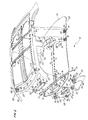
- FIG 2 an exploded view of a modular headliner about to be mounted to a vehicle body structure is shown.
- modular headliner 10 incorporates many various subassemblies such that all the appropriate subassemblies are mounted to the modular headliner and such that they may be readily fastened to the vehicle body structure.
- the wire harness 30 of the modular headliner assembly includes a series of accessory connectors 72 each adapted to be connected to the appropriate electrical accessory mounted to the headliner.
- the wire harness assembly is further shown slightly exploded from channels 31 formed in the substrate for securing the headliner wire harness therein.
- This wire harness assembly is shown somewhat schematically and may, in fact, be located at different positions about the headliner, such positions being chosen for having optimum room for securing wires therein and for providing optimum space between the headliner and the vehicle body structure to prevent any accidental contact therebetween.
- the center console 50 is shown having a complementary connector 74 extending therefrom for connection to accessory connector 72.
- Front console 60 has a complementary connector 97 and sunshade module 130 has a complementary connector 139, designed to be connected to accessory connectors 72 to form the integrated wire harness of the modular headliner assembly.
- Center console 50 and forward console 60 are shown somewhat in schematic format. It is to be understood that these consoles may include features such as overhead lights, reading lights, displays, vanity mirrors, garage door opener compartments,switches, and other control features such that a modular headliner wire harness may include a significant number of conductors. Additionally, the sunshade modules as shown are anticipated to be sunshade modules incorporating illuminated vanity mirrors which likewise require a power supply.
- Center console 50 is mounted through a substrate center module opening 39 formed in depressed portion 51 of the substrate to retainer 52 mounted on the opposite side of the substrate.
- Retainer 52 may have extending wings which act to distribute the load of the console over a wide area of the substrate such that uneven loading or distortion during the shipping or handling process is avoided.
- the substrate about the console is depressed and defines an opening therein.
- the console covers the end of the depression including the opening to form a neat, highly attractive module.
- Mesh fastener 56 attached to a back portion of the retainer or alternatively to the console is designed to interact with mesh fastener 58 secured at location 59 to the roof bows of the vehicle body structure.
- This mesh retainer is preferably a Dual Lock retainer.
- Dual Lock material By the selection of Dual Lock material, it is possible that the headliner may slide into position with one portion of the Dual Lock fastener sliding relative to the other.
- the Dual Lock fastener has the property that it does not grab and lock until the two fasteners are forced one into the other such as when the substrate is displaced upwardly locking it into its final position. Prior to such time, the headliner and the two mesh portions may be slid relative to one another to allow positioning and alignment of the headliner. This is quite different from other mesh fasteners which grab upon contact and may not thereafter be readily displaced.
- Front console 60 is shown having latching fingers 98 which extend upwardly through substrate front console opening 37 formed in depressed portion 61 to engage retainer 62.
- Console 60 also comprises a trim bezel 99 sized to cover opening 37.
- Retainer 62 is in the form of a ring which abuts the substrate about the opening 37 within the depressed portion 61. It includes wings 90 which extend to abut the substrate beyond the inboard sunshade support openings and define wing openings 92 in alignment therewith.
- Inboard sunshade supports 64 and 68 each have a base larger than the substrate inboard support opening and extend with fastening legs 63 projecting upwardly through substrate openings 35, through retainer openings 92 and are secured in position by planar retainer clips 94 including spring-like fingers 96 located one on each side of the legs 63 and, upon final assembly, extend through header openings 126 in the vehicle body structure.
- the retainer ring is sufficiently sized to distribute the weight of the console and inboard sunshade supports over a large enough portion of the substrate to prevent damage to the substrate prior to assembly of the headliner to the motor vehicle.
- Each of the inboard sunshade supports 64 and 68 includes a receptacle 67 for a secondary visor and a slot 65 for receiving a primary visor 65.
- the module includes a primary visor 132 and a secondary visor 134.
- the primary visor is mounted on the pivot rod 136 and the secondary visor is mounted on the pivot rod 137.
- the sunshade module further includes fastener 44, 46 having a base 170, cover 150 and wires 138 extending therebetween.
- the primary visor is mounted for pivoted movement with pivot rod 136 and for rotation about the pivot rod 136 between a stored position against the headliner and a downward position to shield an occupant's eyes from sunlight entering through the windshield.
- the secondary visor may be rotated downwardly to block sunlight entering in through the windshield.
- the forward console 60 includes a pair of lamps, switches for operating each lamp, and a lens for each lamp. It may also comprise a display for indicating the condition of selected components of the motor vehicle, and/or a storage compartment.
- Assist straps 80 include projecting legs 84 projecting through the headliner substrate. Retainers 82 are shown in engagement with legs 84 to secure the assist straps to the headliner.
- An assist strap may include handle 86 and a coat hook 88, and is mounted in an appropriate position to provide a grab handle for an occupant entering or leaving the vehicle.
- Assist strap openings 105 are shown defined by inside rail 104 of the vehicle body structure 100. It is to these assist strap openings 105 that legs 82 engage to hold the assist strap and consequently the modular headliner in position.
- Fastener 44 engages the vehicle body structure through left A-pillar opening 112 formed in left A-pillar inner 108, a portion of A-pillar 22.
- right fastener 46 is inserted through the right A-pillar opening 110 of right A-pillar inner 106, a portion of right A-pillar 24. Both fasteners are likewise mounted through header left sunshade fastener 124 and header right sunshade fastener 122 openings, both being openings in header 120.
- Vehicle body structure 100 as shown includes a series of roof bows 102 and the header and A-pillars as previously mentioned. Additionally, vehicle body structure 100 includes side rail 104 defining openings 105 to which the various assist strap legs may be engaged.
- the entire modular headliner assembly may be secured to the vehicle body structure with the vehicle body structure merely providing appropriately sized and positioned openings. No other structure need be added to the vehicle body structure to allow the modular headliner to be secured thereto. All the fasteners for securing the modular headliner are affixed to the modular headliner such that the vehicle assembler need only mount the modular headliner to the vehicle body structure and need not add any intermediate fastener or receptacle portions to do such except for mesh fastener 58.
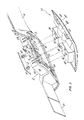
- FIG. 3 is an exploded, perspective view of retainer 52 and console 50 shown as a portion of the modular headliner.
- Retainer 52 is shown having walls 300 extending in a generally vertical direction, having flexible fingers 310 extending inwardly therefrom and shelf 302 extending outwardly therefrom. Additionally, latching fingers308 extend below and outwardly from wall 300.
- the retainer defines a central cavity 312 into which console 50 may be mounted, the console containing the selected accessories for the chosen headliner.
- Console 50 includes trim bezel 400, lamp housings 404 and 406 wherein lamps may be mounted, electrical connector 402, catch 410, slots 412 formed in the lamp housing and switch housing 408 wherein any number of switches or similar components may be mounted.
- the retainer may additionally include a back panel 320 (not directly shown) to which a Dual Lock fastener 56 having a pair of snap fasteners 323 may be secured. These fasteners may be snap-fit into an opening in back panel 320 (not shown) using snap fasteners 323 to which the Dual Lock is secured.
- Electrical connector 352 may also be a portion of the retainer such that assembly of the console to the retainer acts to electrically engage connector 402 mounted to the console to connector 352 mounted to the retainer. Wires 353 are shown extending from connector 352 to the headliner wire harness.
- Shelf 302 is mounted to the retainer and may define shelf openings 304 therein through which or adjacent to which adhesive 306 is applied to additionally secure the retainer to the substrate.
- Latching fingers 308 are provided such that upon assembly of the retainer to the substrate through substrate opening 39, the shelf will sit on top of the substrate and the latching fingers will engage the bottom of the substrate to sandwich the substrate therebetween to lock the retainer in position.
- the substrate is originally formed or molded to create a depressed portion 340 to which the retainer and console are mounted. It is within this depressed portion that substrate opening 39 is formed. Shelf 302 sits on the substrate within the depressed portion. As may be seen in Figure 3, the nondepressed portion of the substrate is substantially the same height as the top of the retainer. In this manner, retainer wings 54 which may extend outwardly from the retainer, may act to engage the top of the nondepressed portions of the substrate. The retainer wings are of significant area such that the load or weight from the console and retainer may be distributed over wide areas of the substrate. This weight distribution acts to prevent the modular headliner from being distorted during the assembly and shipping process due to the weight of the console and retainer.
- Flexible fingers 310 extend inwardly and may coact with catches 410 of console 50 or console 50 may additionally have mounting means such that as console 50 is snap-fitted into the retainer, the two are secured together.
- Housing fingers 314 extend downwardly from retainer 52 within cavity 312 and are positioned to engage slots 412 of lamp housings 404 and 406 to further secure the console to the retainer.
- Trim bezel 400 is shown as a part of console 50 and extends to cover latching fingers 308 and substrate openings 39 such that the trim bezel mates with the depressed portion of the substrate at the decorative surface to provide a quality looking console mounted to the headliner. The latching fingers should not be observable to the vehicle occupant after assembly.
Landscapes
- Engineering & Computer Science (AREA)
- Mechanical Engineering (AREA)
- Arrangements Of Lighting Devices For Vehicle Interiors, Mounting And Supporting Thereof, Circuits Therefore (AREA)
- Vehicle Interior And Exterior Ornaments, Soundproofing, And Insulation (AREA)
- Securing Globes, Refractors, Reflectors Or The Like (AREA)
- Vehicle Step Arrangements And Article Storage (AREA)
Applications Claiming Priority (2)
| Application Number | Priority Date | Filing Date | Title |
|---|---|---|---|
| US205130 | 1988-06-10 | ||
| US07/205,130 US4844533A (en) | 1988-06-10 | 1988-06-10 | Front lamp module and sunshade supports for modular headliner |
Publications (3)
| Publication Number | Publication Date |
|---|---|
| EP0347149A2 true EP0347149A2 (fr) | 1989-12-20 |
| EP0347149A3 EP0347149A3 (fr) | 1991-02-27 |
| EP0347149B1 EP0347149B1 (fr) | 1994-02-16 |
Family
ID=22760922
Family Applications (1)
| Application Number | Title | Priority Date | Filing Date |
|---|---|---|---|
| EP89305917A Expired - Lifetime EP0347149B1 (fr) | 1988-06-10 | 1989-06-12 | Module de lampe frontale et supports de pare-soleil pour garniture de toit modulaire |
Country Status (4)
| Country | Link |
|---|---|
| US (1) | US4844533A (fr) |
| EP (1) | EP0347149B1 (fr) |
| DE (1) | DE68913081T2 (fr) |
| ES (1) | ES2051359T3 (fr) |
Cited By (6)
| Publication number | Priority date | Publication date | Assignee | Title |
|---|---|---|---|---|
| EP0453611A1 (fr) * | 1988-11-02 | 1991-10-30 | EMPE-WERKE ERNST PELZ GmbH & CO. KG | Pavillon autoportant pour véhicules automobiles |
| DE4202907C1 (fr) * | 1992-02-01 | 1993-02-11 | Hella Kg Hueck & Co, 4780 Lippstadt, De | |
| DE19533897A1 (de) * | 1995-09-13 | 1997-03-20 | Happich Gmbh Gebr | Dachverkleidungselement für Fahrzeuge |
| DE19909080A1 (de) * | 1998-03-04 | 2000-04-20 | Rover Group | Dachhimmel-Konsolenbaugruppe für ein Kraftfahrzeug |
| US6899449B2 (en) | 2000-09-28 | 2005-05-31 | Yazaki Corporation | Lamp unit assembling method and lamp unit mounting structure |
| US7500703B2 (en) * | 2007-02-06 | 2009-03-10 | Toyota Motor Engineering & Manufacturing North America, Inc. | Soft edge insert |
Families Citing this family (42)
| Publication number | Priority date | Publication date | Assignee | Title |
|---|---|---|---|---|
| US4893867A (en) * | 1988-06-10 | 1990-01-16 | United Technologies Automotive Inc. | Console mounted to a headliner |
| US5475366A (en) * | 1988-12-05 | 1995-12-12 | Prince Corporation | Electrical control system for vehicle options |
| US5614885A (en) * | 1988-12-05 | 1997-03-25 | Prince Corporation | Electrical control system for vehicle options |
| US5154617A (en) * | 1989-05-09 | 1992-10-13 | Prince Corporation | Modular vehicle electronic system |
| US5040990A (en) * | 1989-05-09 | 1991-08-20 | Prince Corporation | Modular vehicle electronic system |
| US5062559A (en) * | 1989-08-01 | 1991-11-05 | United Technologies Automotive | Overhead console |
| US5061005A (en) * | 1989-08-16 | 1991-10-29 | Prince Corporation | Snap-in visor mount |
| US5056853A (en) * | 1989-08-16 | 1991-10-15 | Prince Corporation | Snap-in visor mount |
| US4989911A (en) * | 1989-08-16 | 1991-02-05 | Prince Corporation | Snap-in visor mount |
| US5455716A (en) * | 1990-08-14 | 1995-10-03 | Prince Corporation | Vehicle mirror with electrical accessories |
| US5106143A (en) * | 1990-08-31 | 1992-04-21 | Prince Corporation | Snap-in floor console |
| US5309634A (en) * | 1992-04-28 | 1994-05-10 | Prince Corporation | Method of assembling electrical circuit to vehicle panel |
| US5475577A (en) * | 1992-07-07 | 1995-12-12 | Donnelly Corporation | Accessory attachment plate for vehicle panels |
| US5357408A (en) * | 1993-10-08 | 1994-10-18 | United Technologies Automotive, Inc. | Interior lamp for an automotive vehicle |
| US5388880A (en) * | 1994-01-07 | 1995-02-14 | Ford Motor Company | Vehicular compartment for remote control transmitter |
| WO1996009952A1 (fr) * | 1994-09-27 | 1996-04-04 | Donnelly Corporation | Ensemble panneau modulaire |
| US5667896A (en) * | 1995-04-11 | 1997-09-16 | Donnelly Corporation | Vehicle window assembly for mounting interior vehicle accessories |
| US6176536B1 (en) * | 1997-07-14 | 2001-01-23 | Lear Donnelly Overhead Systems L.L.C. | Vehicle soft console with interchangeable accessory bins and in-molded skin and fastener |
| US6021986A (en) * | 1997-07-24 | 2000-02-08 | Lear Automotive Dearborn, Inc. | Snap-in mount |
| ES2235224T3 (es) * | 1997-09-30 | 2005-07-01 | Sefind Servizi E Forniture Industriali S.R.L. | Tuberia rigida con juntas para el acondicionamiento de aire en un avion. |
| US6003928A (en) * | 1997-10-14 | 1999-12-21 | Lear Automotive Dearborn, Inc. | Interior trim attachment apparatus for an automotive vehicle |
| JP3569617B2 (ja) * | 1997-11-13 | 2004-09-22 | 本田技研工業株式会社 | 車両のスイッチ取付構造 |
| US6015126A (en) * | 1998-06-01 | 2000-01-18 | Lear Automotive Dearborn, Inc. | Triangular snap-in mount |
| US6412848B1 (en) * | 1999-11-02 | 2002-07-02 | Rosen Products Llc | Vehicle display monitor system |
| US7168138B2 (en) | 2000-03-27 | 2007-01-30 | Newfrey Llc | Resilient clip fastener |
| RU2175919C1 (ru) * | 2000-03-28 | 2001-11-20 | Открытое акционерное общество "АВТОВАЗ" | Установочный узел транспортного средства |
| US6827384B2 (en) * | 2001-05-01 | 2004-12-07 | Johnson Controls Technology Company | Modular system for a vehicle |
| US6824185B2 (en) | 2003-02-28 | 2004-11-30 | Lear Corporation | Modular overhead console assembly |
| DE10336583A1 (de) * | 2003-08-08 | 2005-02-24 | Arvinmeritor Gmbh | Fahrzeuginnenhimmel und Verfahren zum Herstellen eines Fahrzeugdachs |
| US20050062294A1 (en) * | 2003-09-24 | 2005-03-24 | Tai-Hsiung Wu | Locking device for a ceiling mounted movie player |
| US6926333B2 (en) * | 2003-12-22 | 2005-08-09 | Lear Corporation | Modular overhead console assembly |
| DE602004004054T2 (de) * | 2004-01-08 | 2007-06-06 | Grupo Antolín-Ingeniería S.A. | Stützstruktur für eine Innenraumkonsole des Panoramadaches eines Kraftfahrzeuges |
| US7052068B2 (en) * | 2004-10-04 | 2006-05-30 | Lear Corporation | Configurable overhead console |
| US20070046054A1 (en) * | 2005-08-31 | 2007-03-01 | Hinman David T | Interior trim accessory attachment apparatus |
| US9376043B2 (en) * | 2011-11-14 | 2016-06-28 | Ford Global Technologies, Llc | Cushion pan for a vehicle seat assembly |
| CN103057489B (zh) * | 2013-01-05 | 2015-08-19 | 杭州普拉格新能源汽车有限公司 | 一种电驱动汽车动力控制盒 |
| US9987950B2 (en) * | 2016-04-20 | 2018-06-05 | Ford Global Technologies, Llc | Vehicle seat electrical connector bracket assembly |
| US10065483B2 (en) | 2016-10-28 | 2018-09-04 | Teraflex, Inc. | Modular sun visor system |
| US10596939B2 (en) | 2017-12-13 | 2020-03-24 | Ford Global Technologies, Llc | Polymeric seat cushion frame integrated module attachment system |
| US10632883B2 (en) * | 2018-01-25 | 2020-04-28 | Ford Global Technologies, Llc | Multifunctional seat bracket for vehicular seating assembly |
| DE102021104809A1 (de) | 2021-03-01 | 2022-09-01 | Bayerische Motoren Werke Aktiengesellschaft | Dachmodul, Fahrzeugkarosserie und Verfahren zum Herstellen einer Fahrzeugkarosserie |
| DE102022130324A1 (de) * | 2022-11-16 | 2024-05-16 | Bayerische Motoren Werke Aktiengesellschaft | Bewegungs-erkennungssystem für ein kraftfahrzeug |
Family Cites Families (12)
| Publication number | Priority date | Publication date | Assignee | Title |
|---|---|---|---|---|
| US3773378A (en) * | 1972-08-22 | 1973-11-20 | D Lewis | Vehicle overhead console |
| US4188440A (en) * | 1975-07-02 | 1980-02-12 | Van Dresser Corporation | Self-supporting automotive liner panel |
| US4100372A (en) * | 1976-06-25 | 1978-07-11 | Louis Hypolite | Audio console system for home and vehicle |
| US4101159A (en) * | 1977-07-12 | 1978-07-18 | Stewart Buster D | Van overhead console |
| US4211590A (en) * | 1978-07-21 | 1980-07-08 | Inmont Corporation | Method of making perforated contoured trim panel |
| US4241870A (en) * | 1978-10-23 | 1980-12-30 | Prince Corporation | Remote transmitter and housing |
| US4352522A (en) * | 1980-09-29 | 1982-10-05 | Allen Industries, Inc. | Automobile headliner and method of making same |
| DE3208804A1 (de) * | 1982-03-11 | 1983-09-29 | Adam Opel AG, 6090 Rüsselsheim | Innenverkleidung (himmel) von fahrzeugdaechern |
| US4610478A (en) * | 1984-03-01 | 1986-09-09 | General Motors Corporation | Fiberglass headliner with integral roof bows and roof rails |
| DE3442877A1 (de) * | 1984-11-24 | 1986-06-05 | Daimler-Benz Ag, 7000 Stuttgart | Befestigungselement |
| DE3636364C1 (en) * | 1986-10-25 | 1987-05-21 | Daimler Benz Ag | Receiving means for fastening bolts |
| US4684164A (en) * | 1986-10-27 | 1987-08-04 | Durham Timothy N | Apparatus for housing and deploying a radar detector in an automotive vehicle |
-
1988
- 1988-06-10 US US07/205,130 patent/US4844533A/en not_active Expired - Lifetime
-
1989
- 1989-06-12 ES ES89305917T patent/ES2051359T3/es not_active Expired - Lifetime
- 1989-06-12 EP EP89305917A patent/EP0347149B1/fr not_active Expired - Lifetime
- 1989-06-12 DE DE68913081T patent/DE68913081T2/de not_active Expired - Fee Related
Cited By (8)
| Publication number | Priority date | Publication date | Assignee | Title |
|---|---|---|---|---|
| EP0453611A1 (fr) * | 1988-11-02 | 1991-10-30 | EMPE-WERKE ERNST PELZ GmbH & CO. KG | Pavillon autoportant pour véhicules automobiles |
| DE4202907C1 (fr) * | 1992-02-01 | 1993-02-11 | Hella Kg Hueck & Co, 4780 Lippstadt, De | |
| DE19533897A1 (de) * | 1995-09-13 | 1997-03-20 | Happich Gmbh Gebr | Dachverkleidungselement für Fahrzeuge |
| DE19909080A1 (de) * | 1998-03-04 | 2000-04-20 | Rover Group | Dachhimmel-Konsolenbaugruppe für ein Kraftfahrzeug |
| US6899449B2 (en) | 2000-09-28 | 2005-05-31 | Yazaki Corporation | Lamp unit assembling method and lamp unit mounting structure |
| DE10148107B4 (de) * | 2000-09-28 | 2012-01-19 | Yazaki Corp. | Verfahren zum Einbauen einer Leuchteinheit und Befestigungsanordnung für eine Leuchteinheit |
| DE10148107B9 (de) * | 2000-09-28 | 2013-08-14 | Yazaki Corp. | Verfahren zum Einbauen einer Leuchteinheit und Befestigungsanordnung für eine Leuchteinheit |
| US7500703B2 (en) * | 2007-02-06 | 2009-03-10 | Toyota Motor Engineering & Manufacturing North America, Inc. | Soft edge insert |
Also Published As
| Publication number | Publication date |
|---|---|
| ES2051359T3 (es) | 1994-06-16 |
| DE68913081D1 (de) | 1994-03-24 |
| US4844533A (en) | 1989-07-04 |
| DE68913081T2 (de) | 1994-07-07 |
| EP0347149B1 (fr) | 1994-02-16 |
| EP0347149A3 (fr) | 1991-02-27 |
Similar Documents
| Publication | Publication Date | Title |
|---|---|---|
| EP0347149B1 (fr) | Module de lampe frontale et supports de pare-soleil pour garniture de toit modulaire | |
| US4893867A (en) | Console mounted to a headliner | |
| EP0346157B1 (fr) | Structure recevant des fixations d'assemblage à enclenchement d'un revêtement de toît modulaire dans la carrosserie d'un véhicule automobile | |
| US4902068A (en) | Modular headliner assembly | |
| US4981323A (en) | Assist strap for a modular headliner | |
| US5269060A (en) | Method of aligning and installing an automobile headliner by a previously attached sunshade assembly | |
| EP0346158B1 (fr) | Fixation pour revêtement de toît et pare-soleil | |
| US5082323A (en) | Sunshade fastener module for use with modular headliner | |
| US5105521A (en) | Method of assembling modular headliner to a vehicle by snap-fitting | |
| US4981322A (en) | Assist strap for a motor vehicle | |
| EP0411581B1 (fr) | Console de toit | |
| US6338517B1 (en) | Overhead console for a vehicle | |
| EP0346154B1 (fr) | Garniture de toit modulaire comprenant un câblage électrique | |
| EP0912371B1 (fr) | Ensemble a faisceau de cables sur panneau de garnissage | |
| US5365416A (en) | Sun visor with integral core | |
| US7097225B2 (en) | Transparent vehicle roof with arrangement for receiving articles | |
| JP3293740B2 (ja) | 自動車用ルーフモジュール | |
| US5374097A (en) | Universal visor mounting system | |
| US6038764A (en) | Method of distributing a wire harness to a wall surface by detachably locking the wire harness on a trimming plate | |
| US5169105A (en) | Apparatus and method for supporting an accessory unit within an automobile console | |
| EP0346156B1 (fr) | Poignée auxiliaire pour revêtement de toît modulaire | |
| EP0346155A2 (fr) | Ensemble de revêtement de toit modulaire | |
| US7393046B2 (en) | Removable storage module for vehicle | |
| EP0912372B1 (fr) | Assemblage de cablage electrique sur un panneau de garnissage | |
| US20050242628A1 (en) | Removable storage module for vehicle |
Legal Events
| Date | Code | Title | Description |
|---|---|---|---|
| PUAI | Public reference made under article 153(3) epc to a published international application that has entered the european phase |
Free format text: ORIGINAL CODE: 0009012 |
|
| AK | Designated contracting states |
Kind code of ref document: A2 Designated state(s): DE ES FR GB IT |
|
| PUAL | Search report despatched |
Free format text: ORIGINAL CODE: 0009013 |
|
| AK | Designated contracting states |
Kind code of ref document: A3 Designated state(s): DE ES FR GB IT |
|
| 17P | Request for examination filed |
Effective date: 19910614 |
|
| 17Q | First examination report despatched |
Effective date: 19930212 |
|
| GRAA | (expected) grant |
Free format text: ORIGINAL CODE: 0009210 |
|
| AK | Designated contracting states |
Kind code of ref document: B1 Designated state(s): DE ES FR GB IT |
|
| ITF | It: translation for a ep patent filed | ||
| REF | Corresponds to: |
Ref document number: 68913081 Country of ref document: DE Date of ref document: 19940324 |
|
| REG | Reference to a national code |
Ref country code: ES Ref legal event code: FG2A Ref document number: 2051359 Country of ref document: ES Kind code of ref document: T3 |
|
| ET | Fr: translation filed | ||
| PLBE | No opposition filed within time limit |
Free format text: ORIGINAL CODE: 0009261 |
|
| STAA | Information on the status of an ep patent application or granted ep patent |
Free format text: STATUS: NO OPPOSITION FILED WITHIN TIME LIMIT |
|
| 26N | No opposition filed | ||
| REG | Reference to a national code |
Ref country code: FR Ref legal event code: TP |
|
| PGFP | Annual fee paid to national office [announced via postgrant information from national office to epo] |
Ref country code: ES Payment date: 19990604 Year of fee payment: 11 |
|
| PGFP | Annual fee paid to national office [announced via postgrant information from national office to epo] |
Ref country code: GB Payment date: 20000519 Year of fee payment: 12 |
|
| PG25 | Lapsed in a contracting state [announced via postgrant information from national office to epo] |
Ref country code: ES Free format text: THE PATENT HAS BEEN ANNULLED BY A DECISION OF A NATIONAL AUTHORITY Effective date: 20000613 |
|
| PG25 | Lapsed in a contracting state [announced via postgrant information from national office to epo] |
Ref country code: GB Free format text: LAPSE BECAUSE OF NON-PAYMENT OF DUE FEES Effective date: 20010612 |
|
| GBPC | Gb: european patent ceased through non-payment of renewal fee |
Effective date: 20010612 |
|
| REG | Reference to a national code |
Ref country code: ES Ref legal event code: FD2A Effective date: 20020204 |
|
| PGFP | Annual fee paid to national office [announced via postgrant information from national office to epo] |
Ref country code: FR Payment date: 20040618 Year of fee payment: 16 |
|
| PG25 | Lapsed in a contracting state [announced via postgrant information from national office to epo] |
Ref country code: IT Free format text: LAPSE BECAUSE OF NON-PAYMENT OF DUE FEES;WARNING: LAPSES OF ITALIAN PATENTS WITH EFFECTIVE DATE BEFORE 2007 MAY HAVE OCCURRED AT ANY TIME BEFORE 2007. THE CORRECT EFFECTIVE DATE MAY BE DIFFERENT FROM THE ONE RECORDED. Effective date: 20050612 |
|
| PGFP | Annual fee paid to national office [announced via postgrant information from national office to epo] |
Ref country code: DE Payment date: 20050801 Year of fee payment: 17 |
|
| PG25 | Lapsed in a contracting state [announced via postgrant information from national office to epo] |
Ref country code: FR Free format text: LAPSE BECAUSE OF NON-PAYMENT OF DUE FEES Effective date: 20060228 |
|
| REG | Reference to a national code |
Ref country code: FR Ref legal event code: ST Effective date: 20060228 |
|
| PG25 | Lapsed in a contracting state [announced via postgrant information from national office to epo] |
Ref country code: DE Free format text: LAPSE BECAUSE OF NON-PAYMENT OF DUE FEES Effective date: 20070103 |