EP0347223A2 - Indicateur de poussières pour dispositif de nettoyage par succion - Google Patents
Indicateur de poussières pour dispositif de nettoyage par succion Download PDFInfo
- Publication number
- EP0347223A2 EP0347223A2 EP89306070A EP89306070A EP0347223A2 EP 0347223 A2 EP0347223 A2 EP 0347223A2 EP 89306070 A EP89306070 A EP 89306070A EP 89306070 A EP89306070 A EP 89306070A EP 0347223 A2 EP0347223 A2 EP 0347223A2
- Authority
- EP
- European Patent Office
- Prior art keywords
- light
- dust
- suction passage
- detecting
- dust suction
- Prior art date
- Legal status (The legal status is an assumption and is not a legal conclusion. Google has not performed a legal analysis and makes no representation as to the accuracy of the status listed.)
- Granted
Links
Images



Classifications
-
- A—HUMAN NECESSITIES
- A47—FURNITURE; DOMESTIC ARTICLES OR APPLIANCES; COFFEE MILLS; SPICE MILLS; SUCTION CLEANERS IN GENERAL
- A47L—DOMESTIC WASHING OR CLEANING; SUCTION CLEANERS IN GENERAL
- A47L9/00—Details or accessories of suction cleaners, e.g. mechanical means for controlling the suction or for effecting pulsating action; Storing devices specially adapted to suction cleaners or parts thereof; Carrying-vehicles specially adapted for suction cleaners
- A47L9/28—Installation of the electric equipment, e.g. adaptation or attachment to the suction cleaner; Controlling suction cleaners by electric means
-
- A—HUMAN NECESSITIES
- A47—FURNITURE; DOMESTIC ARTICLES OR APPLIANCES; COFFEE MILLS; SPICE MILLS; SUCTION CLEANERS IN GENERAL
- A47L—DOMESTIC WASHING OR CLEANING; SUCTION CLEANERS IN GENERAL
- A47L9/00—Details or accessories of suction cleaners, e.g. mechanical means for controlling the suction or for effecting pulsating action; Storing devices specially adapted to suction cleaners or parts thereof; Carrying-vehicles specially adapted for suction cleaners
- A47L9/28—Installation of the electric equipment, e.g. adaptation or attachment to the suction cleaner; Controlling suction cleaners by electric means
- A47L9/2857—User input or output elements for control, e.g. buttons, switches or displays
-
- A—HUMAN NECESSITIES
- A47—FURNITURE; DOMESTIC ARTICLES OR APPLIANCES; COFFEE MILLS; SPICE MILLS; SUCTION CLEANERS IN GENERAL
- A47L—DOMESTIC WASHING OR CLEANING; SUCTION CLEANERS IN GENERAL
- A47L9/00—Details or accessories of suction cleaners, e.g. mechanical means for controlling the suction or for effecting pulsating action; Storing devices specially adapted to suction cleaners or parts thereof; Carrying-vehicles specially adapted for suction cleaners
- A47L9/28—Installation of the electric equipment, e.g. adaptation or attachment to the suction cleaner; Controlling suction cleaners by electric means
- A47L9/2805—Parameters or conditions being sensed
- A47L9/281—Parameters or conditions being sensed the amount or condition of incoming dirt or dust
- A47L9/2815—Parameters or conditions being sensed the amount or condition of incoming dirt or dust using optical detectors
-
- A—HUMAN NECESSITIES
- A47—FURNITURE; DOMESTIC ARTICLES OR APPLIANCES; COFFEE MILLS; SPICE MILLS; SUCTION CLEANERS IN GENERAL
- A47L—DOMESTIC WASHING OR CLEANING; SUCTION CLEANERS IN GENERAL
- A47L9/00—Details or accessories of suction cleaners, e.g. mechanical means for controlling the suction or for effecting pulsating action; Storing devices specially adapted to suction cleaners or parts thereof; Carrying-vehicles specially adapted for suction cleaners
- A47L9/28—Installation of the electric equipment, e.g. adaptation or attachment to the suction cleaner; Controlling suction cleaners by electric means
- A47L9/2836—Installation of the electric equipment, e.g. adaptation or attachment to the suction cleaner; Controlling suction cleaners by electric means characterised by the parts which are controlled
- A47L9/2842—Suction motors or blowers
Definitions
- the present invention relates to a dust detector for optically detecting the quantity of dust flowing through a suction passage in a vacuum cleaner and controlling the rotational speed of the fan motor, for example, based on the detected quantity of dust.
- the disclosed dust detector comprises an optical sensor including a light transmitter and a light receiver.
- Light is emitted by the light transmitter into the suction passage toward the light receiver.
- the intensity of light detected by the light receiver is varied depending on how much light is cut off or reflected by dust particles flowing through the suction passage.
- the quantity of dust passing through the suction passage is indirectly detected from a variation in the output signal from the light receiver.
- the rotational speed of the fan motor of the vacuum cleaner or a cleanliness indicator on the vacuum cleaner is controlled based on the detected amount of dust.
- the rotational speed of the fan motor is increased for creating greater suction power.
- the condition indicating a large quantity of dust flowing through the suction passage, i.e., when a surface has not yet been cleaned up, and the condition indicating a small quantity of dust flowing through the suction passage, i.e., when a surface has almost been cleaned up, are indicated respectively by differently colored lamps to allow the user of the vacuum cleaner to clean desired surfaces efficiently.
- the light transmitter and the light receiver of the optical sensor are positioned such that they are exposed into the suction passage through which dust flows.
- dust particles tend to be attached to the exposed surfaces of the light transmitter and the light receiver, through which light is emitted and detected, resulting in poor performance of the optical sensor. This problem has prevented vacuum cleaners with optical dust detectors from finding practical use.
- the present invention provides, a dust detector for a vacuum cleaner, comprising a dust suction passage for passage of dust therethrough, a light-emitting element exposed into the dust suction passage for emitting a light beam into the dust passage, a light-detecting element exposed into the dust suction passage for detecting the light beam emitted from the light-emitting element, a detector unit for detecting the amount of dust flowing through the dust suction passage based on the intensity of the light beam transmitted from the light-emitting element across the dust suction passage to the light-detecting element, and a pair of light-transmissive covers covering the light-emitting element and the light-detecting elements, respectively, and having respective end faces exposed into the dust suction passage and lying flush with an inner wall surface of the dust suction passage.
- the light-emitting element and light-detecting element may be covered with light-transmissive covers, the light-transmissive cover which covers the light-emitting element having a light-emitting end of a reduced diameter for emitting a constant-diameter light beam without light dispersion to permit reliable dust detection.
- the covers may have exposed end faced hardened for protection against damage by dust particles.
- a dust detector for a vacuum cleaner comprising a dust suction passage for flow of dust therethrough, a light-emitting element for emitting a light beam into the dust passage, a light-detecting element for detecting the light beam emitted from the light-emitting element, and a detector unit for detecting the amount of dust flowing through the dust suction passage based on an output signal from the light-detecting element, the dust suction passage having an inner taper surface having a smaller diameter at a downstream end with respect to the flow, the light-emitting element and the light-detecting element being positioned near the downstream end of the inner taper surface.
- a dust detector for a vacuum cleaner comprising a dust suction passage for flow of dust therethrough, a dust sensor disposed in the dust suction passage and comprising a light-emitting element and a light-detecting element, the dust sensor including means for detecting the quantity of dust flowing through the dust suction passage based on the intensity of light transmitted from the light-emitting element across the dust suction passage to the light-detecting element, a pair of air passages in which the light-emitting element and the light-detecting elements are disposed, respectively, each of the air passages having one end vented to atmosphere and the other end opening into the dust suction passage, and a pair of pressure-responsive valves disposed in the air passages, respectively, for selectively opening and closing the air passages depending on a pressure in the dust suction passage.
- means are provided for introducing ambient air along the light-emitting and -detecting elements depending on the pressure in a vacuum cleaner suction passage, to clean the light-emitting and -detecting
- a dust detector for a vacuum cleaner comprising a dust suction passage for passage of dust therethrough in a direction, a dust sensor comprising a light-emitting element and a light-detecting element, the dust suction passage being positioned between the light-emitting element and the light-detecting element, the dust sensor including means for detecting the quantity of dust flowing through the dust suction passage based on the intensity of light transmitted from the light-emitting element across the dust suction passage to the light-detecting element, the light-detecting element having an axis inclined with respect to the direction, and a pair of light-transmissive covers covering the light-emitting element and the light-detecting element, respectively.
- a dust detector for a vacuum cleaner comprising a dust suction passage for passage of dust therethrough, and a dust sensor disposed in the dust suction passage and comprising a light-emitting element and a light-detecting element, the dust sensor including means for detecting the quantity of dust flowing through the dust suction passage based on the intensity of light transmitted from the light-emitting element across the dust suction passage to the light-detecting element, the dust suction passage being defined by a wall including portions near the light-emitting element and the light-detecting element, the portions being of a black or dark color.
- dust detector in a vacuum cleaner comprising a dust suction passage for passage of dust therethrough, and a dust sensor disposed in the dust suction passage and comprising a light-emitting element and a light-detecting element, the dust sensor including means for detecting the quantity of dust flowing through the dust suction passage based on the intensity of light transmitted from the light-emitting element across the dust suction passage to the light-detecting element, the dust suction passage being defined by a wall including portions near the light-emitting element and the light-detecting element, the portions being molded of a synthetic resin containing an infrared radiation absorbent.
- the invention also relates to vacuum cleaners incorporating such dust detectors.
- a vacuum cleaner comprising a main vacuum cleaner unit having a suction inlet, a handle defining therein a dust suction passage for passage of dust therethrough, a light-emitting element for emitting a light beam into the dust passage, a light-detecting element for detecting the light beam emitted from the light-emitting element, a detector unit for detecting the amount of dust flowing through the dust suction passage based on an output signal from the light-detecting element, and a hose interconnecting the dust suction passage in the handle and the suction inlet of the main vacuum cleaner unit, the hose comprising outer and inner wound tapes and a core sandwiched between the outer and inner wound tapes, at least one of the outer and inner wound tapes being of black or dark color.
- a vacuum cleaner includes a main vacuum cleaner unit 1 movable on a floor and housing known mechanisms such as an air suction fan motor and a dust filter (not shown), a hose 2 connected at one end to an air inlet end of the main vacuum cleaner unit 1 and at the other end to a dust suction passage 4 (FIG. 2) defined in a handle 3, and a pipe 6 having one end connected to an upstream end of the dust suction passage 4 and the other end coupled to a floor nozzle 5.
- known mechanisms such as an air suction fan motor and a dust filter (not shown)
- hose 2 connected at one end to an air inlet end of the main vacuum cleaner unit 1 and at the other end to a dust suction passage 4 (FIG. 2) defined in a handle 3
- a pipe 6 having one end connected to an upstream end of the dust suction passage 4 and the other end coupled to a floor nozzle 5.
- Dust-laden air drawn by the floor nozzle 5 flows from the pipe 6 through the dust suction passage 4 in the handle 3 and the hose 2 into the filter in the main vacuum cleaner unit 1. Dust particles are trapped by the dust filter, and then clean air is discharged out of the main vacuum cleaner unit 1 by the fan motor.
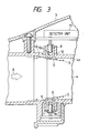
- a dust detector according to the present invention comprises a sensor disposed in the suction passage 4 in the handle 3.
- the sensor comprises a light-emitting element 7 such as a light-emitting diode, for example, and a light-detecting element 8 such as a photodiode, for example.
- the light-emitting element 7 and the light-detecting element 8 are positioned on confronting walls across the suction passage 4.
- the light-emitting element 7 and the light-detecting element 8 are inserted respectively in cylindrical light-transmissive covers 9, 10 made of transparent synthetic resin such as acrylic resin.
- the confronting walls of the suction passage 4 have respective holes in which the respective light-transmissive covers 9, 10 are placed.
- the covers 9, 10 have distal ends near the suction passage 4, the distal ends having diameters equal to or smaller than the respective diameters of the light-emitting and -detecting elements 7, 8.
- the distal ends of the covers 9, 10 have end faces, i.e., a light-transmitting end face 9a and a light-receiving end face 10a, exposed into the suction passage 4 and lying flush with an inner wall surface 4a of the suction passage 4.
- the light-transmitting end face 9a and the light-receiving end face 10a are hardened by exposure to ultraviolet radiation.
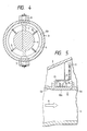
- the light-detecting element 8 is electrically connected to a detector unit 11 (FIG. 4) which converts the intensity of light that has been emitted from the light-emitting element 7 and reached the light-detecting element 8, to an electric signal.
- the detector unit 11 detects the quantity of dust flowing through the suction passage 4 based on the electric signal.
- the dust detector operates as follows: The fan motor is energized to start drawing dust particles from the floor nozzle 5. The dust flows through the suction passage 4 as indicated by the arrow A. Light is emitted from the light-emitting element 7 and directed toward the light-detecting element 8. The greater the quantity of dust flowing through the suction passage 4, the lower the intensity of light that has reached the light-detecting element 8 because the transmittance of light across the suction pas sage 4 is lower. Therefore, the intensity of light detected by the light-detecting element 8 is lower as more dust particles flow through the suction passage 4. Based on a detected signal from the light-detecting element 8, the detector unit 11 detects the amount of dust flowing through the suction passage 4.
- the detector unit 11 controls the rotational speed of the fan motor or the like based on the detected amount of dust.
- the end faces 9a, 10a projected into the suction passage 4, they would not only obstruct the air flow through the suction passage 4 but also allow dust particles to impinge upon and be deposited on and around the end faces 9a, 10a. If the end faces 9a, 10a were recessed from the inner wall surface 4a, they would develop swirls to permit dust particles to be deposited on the end faces 9a, 10b. Therefore, the end faces 9a, 10a lying flush with the inner wall surface 4a as shown are effective to prevent dust particles from being deposited thereon.
- the hardened end faces 9a, 10a are highly resistant to damage even when they are hit by hard dust particles. Consequently, the end faces 9a, 10a transmit and receive light effectively without substantial intensity attenuation as they remain transparent.
- the dust sensor which is composed of the light-emitting element 7 and the light-detecting element 8 is positioned near the upstream end of the suction passage 4 which extends through the handle 3, i.e., near the end of the suction passage 4 which is connected to the pipe 6. Therefore, when the pipe 6 is detached from the handle 3, the end faces 9a, l0a of the covers 9, 10 can easily be cleaned by a piece of cloth, for example, inserted into the suction passage 4.
- Each of the end faces 9a, 10a of the covers 9, 10 is smaller in diameter than the other portion of the cover.
- Light emitted from the light-emitting element 7 is shaped into a constant-diameter light beam by the reduced-diameter end face 9a, and the constant-diameter light beam is then transmitted from the end face 9a to the end face 10a. Since the shaped constant-diameter light beam transmitted from the end face 9a to the end face 10a has a sharp boundary, the difference in light intensity between the light beam and a region surrounding the light beam is large, allowing accurate detection of a change in the light intensity which is caused by dust particles flowing across the light beam.
- the inner wall surface 4a of the suction passage 4 has a conical taper surface 4b which is progressively smaller in diameter downstream away from the end of the suction passage 4 to which the pipe 6 is connected.
- the light-emitting element 7 and the light-detecting element 8 are positioned near the terminal end of the conical taper surface 4b.
- Dust-laden air flowing through the suction passage 4 is directed obliquely inwardly toward the center of the suction passage 4 by the conical taper surface 4b. Therefore, dust particles D carried by the air flow are also oriented toward the center of the suction passage 4.
- the air flow itself tends to flow along the inner wall surface 4a due to the Coanda effect downstream of the terminal end of the conical taper surface 4b.
- the dust particles D which have a substantial weight as compared with air move owing to their inertia toward the center of the suction passage 4 as indicated by the arrows G.
- the dust particles D flowing along the inner wall surface 4a are thus forced away from the end faces 9a, 10a positioned downstream of the conical taper surface 4b, and are not attached to or deposited on the end faces 9a, 10a.
- the conical taper surface 4b offers another advantage. Inasmuch as the dust flow in the suction passage 4 downstream of the conical taper surface 4b is directed toward the center of the suction passage 4, the dust particles are concentrated into a shaded region H through which the light beam I is transmitted from the light-emitting element 7 to the light-detecting element 8. The concentrated dust particles can be detected by the light beam I with increased accuracy.
- FIG. 5 shows a dust detector according to another embodiment, the dust detector comprising a light-reflecting sensor.
- the light-reflecting sensor comprises a light-emitting element 13 and a light-detecting element 14 which are housed in a cylindrical light-transmissive cover 12 disposed in the wall of a suction passage 4 and having an end face 12a lying flush with an inner wall surface 4a of the suction passage 4.
- the light-emitting and -detecting elements 13, 14 have central axes inclined with respect to each other, or intersecting with each other, such that light emitted from the light-emitting element 13 is reflected by either a confronting area of the inner wall surface 4a or dust particles flowing through the suction passage 4, and detected by the light-detecting element 14.
- FIGS. 6 and 7 illustrate dust detectors for vacuum cleaners according to other embodiments of the present invention, each having a means for introducing ambient air for cleaning light-emitting and -detecting elements.
- a dust suction passage 21 is defined in and extends through a handle 22.
- a floor nozzle (not shown) is connected to the upstream end of the suction passage 21 through a pipe (not shown).
- the air inlet end of a main vacuum cleaner unit (not shown) is connected to the downstream end of the suction passage 21 through a hose (not shown).
- the wall of the suction passage 21 has a pair of diametrically opposite openings or holes 23, 24 communicating respectively with element chambers 25, 26 defined in the suction passage wall.
- the dust detector comprises a sensor 27 composed of a light-emitting element 28 housed in the element chamber 25 and a light-detecting element 29 housed in the other element chamber 26. The intensity of light emitted from the light-emitting element 28 and detected by the light-detecting element 29 is varied depending on the amount of dust flowing through the suction passage 21 to vary an output signal from the light-detecting element 29.
- Air passages 30, 31 including the element chambers 25, 26 and the openings 23, 24 are defined in the wall of the suction passage 21 for introducing ambient air into the suction passage 21.
- Pressure-responsive valves 32, 33 are disposed in the air passages 30, 31, respectively.
- the pressure-responsive valves 32, 33 comprise valve casings 38, 39, respectively, having valve seats 34, 35, respectively, on upstream ends and holes 36, 37, respectively, in downstream ends, valve members 34, 35, respectively, for opening and closing the valve seats 34, 35 on their downstream sides, and springs 42, 43, respectively, for normally urging the valve members 34, 35 in a direction to close the valve seats 34, 35.
- the vacuum pressure developed in the suction passage 21 falls within a prescribed range.
- the spring forces of the springs 42, 43 are selected so as not to open the valve members 40, 41 when the vacuum pressure in the suction passage 21 is in the prescribed range. Therefore, the air passages 30, 31 remain closed in the prescribed vacuum pressure range.
- the pressure in the suction passage 21 is lowered by the resistance to the air flow. Therefore, the pressure difference across the valve members 40, 41 is increased to open the valve seats 34, 35 against the resiliency of the springs 42, 43.
- Ambient air is now introduced through the air passages 30, 31 into the suction passage 21 to blow off dust particles that may have been deposited on the light-emitting and -detecting elements 28, 29.
- the dust detector according to the yet other embodiment shown in FIG. 7 differs from the dust detector shown in FIG. 6 in that valve seats 44, 35 are provided respectively over the downstream holes 36, 37 and the casings 32, 33 have holes 34′, 35′ defined in their upstream ends, respectively.
- the springs 42, 43 have weaker spring forces selected such that when the pressure in the suction passage 21 is lower than a prescribed pressure level, the valve seats 44, 45 are closed by the valve members 40, 41 due to the difference between the vacuum pressure in the suction passage 21 and the atmospheric pressure.
- the valve members 40, 41 close the valve seats 44, 45 against the bias of the springs 42, 43 due to the difference between the vacuum pressure in the suction passage 21 and the atmospheric pressure.
- the air passages 30, 31 do not remain open at all times, but are opened at a selected time depending on a particular mode of use of the vacuum cleaner, for thereby introducing ambient air to clean the light-emitting and -detecting elements 28, 29. Therefore, the suction performance of the vacuum cleaner itself is maintained at a sufficient level.
- Extraneous light tends to enter the suction passage 4 through the junction between the handle 3 and the pipe 6 (see FIG. 1). Extraneous light of a very low intensity level is also liable to pass through the hose 2 into the suction passage 4. Such extraneous light having entered suction passage 4 is responsible at times for triggering the dust sensor in error.
- FIGS. 8 and 9 show arrangements according to further embodiments of the present invention for preventing extraneous light from erroneously activating the dust sensor.
- a dust suction passage 51 is defined in and extends through a handle 52.
- a floor nozzle (not shown) is connected to the upstream end of the suction passage 51 through a pipe (not shown).
- the air inlet end of a main vacuum cleaner unit (not shown) is connected to the downstream end of the suction passage 51 through a hose (not shown).
- the wall of the suction passage 51 has a pair of opposite openings or holes 53, 54 defined near the upstream end of the suction passage 51 and confronting along a line inclined to the axis of the suction passage 51.
- a dust sensor comprises a light-emitting element 55 and a light-detecting element 56 disposed respectively in the openings 53, 54.
- the light-emitting and -detecting elements 55, 56 are covered respectively with light-transmissive covers 57, 58 made of acrylic resin or the like and having end faces exposed into the suction passage 51.
- the light-detecting element 56 has its axis 59 extending obliquely downstream in the direction in which dust-laden air flows through the suction passage 51, the axis 59 being aligned with the axis of the light-emitting element 55.
- a detector unit detects the amount of dust flowing through the suction passage 51, and controls the rotational speed of the fan motor or operates an indicator based on the detected amount of dust.
- the light-emitting and -detecting elements 55, 56 are disposed near the inlet end of the suction passage 51.
- the axis of the light-detecting element should be inclined upstream in the direction of flow of dust-laden air. That is, the axis of the light-detecting element should be inclined in a direction opposite to the direction in which extraneous light enters the suction passage.
- a dust suction passage 61 is defined in and extends through a handle 62.
- a floor nozzle (not shown) is connected to the upstream end of the suction passage 21 through a pipe (not shown).
- the air inlet end of a main vacuum cleaner unit (not shown) is connected to the downstream end of the suction passage 61 through a hose 63.
- the hose 63 comprises an outer wound tape 66 and an inner wound tape 67 with a piano wire 64 and an electrically conductive wire 65 being coiled and sandwiched between the outer and inner wound tapes 66, 67 to provide a core for keeping the hose 63 cylindrical in shape and flexible. At least one of the outer and inner wound tapes 66, 67 is of a black or dark color.
- the suction passage 61 is defined by a cylindrical wall which is either molded of a synthetic resin containing an infrared radiation absorbent that is substantially incapable of transmitting or reflecting extraneous infrared radiation or coated with a black or dark color paint layer.
- Infrared radiation emitted from a light-emitting element toward a light-detecting element of a dust sensor is cut off by dust particles flowing through the suction passage 61. Since extraneous infrared radiation does not reach the light-detecting element through the hose 63 or the wall of the suction passage 61, the sensitivity of the dust sensor may be increased to enable a dust detector comprising the dust sensor to detect small dust particles with high accuracy.
Landscapes
- Engineering & Computer Science (AREA)
- Mechanical Engineering (AREA)
- Electric Vacuum Cleaner (AREA)
- Filters For Electric Vacuum Cleaners (AREA)
- Processing Of Solid Wastes (AREA)
- Investigating Or Analysing Materials By Optical Means (AREA)
Applications Claiming Priority (8)
| Application Number | Priority Date | Filing Date | Title |
|---|---|---|---|
| JP63147430A JPH01314533A (ja) | 1988-06-15 | 1988-06-15 | 電気掃除機の塵検知装置 |
| JP147430/88 | 1988-06-15 | ||
| JP147471/88 | 1988-06-15 | ||
| JP63147471A JPH01314534A (ja) | 1988-06-15 | 1988-06-15 | 電気掃除機の塵埃検知装置 |
| JP63158549A JPH027925A (ja) | 1988-06-27 | 1988-06-27 | 電気掃除機の塵検知装置 |
| JP158549/88 | 1988-06-27 | ||
| JP63210265A JPH0790013B2 (ja) | 1988-08-24 | 1988-08-24 | 電気掃除機の塵検知装置 |
| JP210265/88 | 1988-08-24 |
Publications (3)
| Publication Number | Publication Date |
|---|---|
| EP0347223A2 true EP0347223A2 (fr) | 1989-12-20 |
| EP0347223A3 EP0347223A3 (en) | 1990-10-03 |
| EP0347223B1 EP0347223B1 (fr) | 1993-08-18 |
Family
ID=27472783
Family Applications (1)
| Application Number | Title | Priority Date | Filing Date |
|---|---|---|---|
| EP89306070A Expired - Lifetime EP0347223B1 (fr) | 1988-06-15 | 1989-06-15 | Indicateur de poussières pour dispositif de nettoyage par succion |
Country Status (5)
| Country | Link |
|---|---|
| US (1) | US5163202A (fr) |
| EP (1) | EP0347223B1 (fr) |
| KR (1) | KR910006887B1 (fr) |
| DE (1) | DE68908489T2 (fr) |
| ES (1) | ES2045436T3 (fr) |
Cited By (18)
| Publication number | Priority date | Publication date | Assignee | Title |
|---|---|---|---|---|
| EP0443845A1 (fr) * | 1990-02-22 | 1991-08-28 | Matsushita Electric Industrial Co., Ltd. | Aspirateur de poussières |
| EP0451787A1 (fr) * | 1990-04-10 | 1991-10-16 | Matsushita Electric Industrial Co., Ltd. | Aspirateur de poussières à contrôle poussé |
| EP0456083A1 (fr) * | 1990-05-05 | 1991-11-13 | Fedag | Dispositif indicateur d'encrassement pour filtre à air d'aspirateur, de conditionnement d'air ou autres |
| EP0456084A1 (fr) * | 1990-05-05 | 1991-11-13 | Fedag | Aspirateur de liquides |
| GB2225933B (en) * | 1988-12-02 | 1992-12-09 | Hoover Plc | Vacuum cleaners having dirt sensors |
| US5319827A (en) * | 1991-08-14 | 1994-06-14 | Gold Star Co., Ltd. | Device of sensing dust for a vacuum cleaner |
| EP0861629A1 (fr) * | 1997-02-25 | 1998-09-02 | YASHIMA ELECTRIC CO., Ltd. | Aspirateur |
| WO2002011599A1 (fr) | 2000-08-07 | 2002-02-14 | Arçelik A.S. | Dispositif de nettoyage pour capteur et aspirateur pourvu d'un tel dispositif de nettoyage |
| WO2009005664A1 (fr) * | 2007-06-29 | 2009-01-08 | Caterpillar Inc. | Système automatisé de réaction à une perte de charge |
| RU2359604C2 (ru) * | 2006-03-14 | 2009-06-27 | Тосиба Тэк Кабусики Каиса | Электрический пылесос (варианты) |
| EP1799087A4 (fr) * | 2004-09-17 | 2009-08-12 | Cube Invest Ltd | Poignee d'un dispositif de nettoyage et sections boitier de poignee de dispositif de nettoyage |
| WO2012000991A1 (fr) * | 2010-06-29 | 2012-01-05 | Aktiebolaget Electrolux | Indicateur de poussière pour aspirateur |
| US8689398B2 (en) | 2009-05-21 | 2014-04-08 | Industrial Technology Research Institute | Cleaning apparatus and detecting method thereof |
| US9015897B2 (en) | 2010-06-29 | 2015-04-28 | Aktiebolaget Electrolux | Dust detection system |
| US9649000B2 (en) | 2012-11-09 | 2017-05-16 | Aktiebolaget Electrolux | Cyclone dust separator arrangement, cyclone dust separator and cyclone vacuum cleaner |
| US9693667B2 (en) | 2004-05-12 | 2017-07-04 | Cube Investments Limited | Central vacuum cleaning system control subsytems |
| US9723962B2 (en) | 2010-10-05 | 2017-08-08 | Samsung Electronics Co., Ltd. | Dust inflow sensing unit and robot cleaner having the same |
| EP2659260B1 (fr) * | 2010-12-30 | 2019-11-20 | iRobot Corporation | Surveillance de détritus |
Families Citing this family (76)
| Publication number | Priority date | Publication date | Assignee | Title |
|---|---|---|---|---|
| KR930005714B1 (ko) * | 1991-06-25 | 1993-06-24 | 주식회사 금성사 | 진공 청소기의 흡입력 제어방법 및 장치 |
| JPH0662991A (ja) * | 1992-08-21 | 1994-03-08 | Yashima Denki Co Ltd | 電気掃除機 |
| US5359907A (en) * | 1992-11-12 | 1994-11-01 | Horiba Instruments, Inc. | Method and apparatus for dry particle analysis |
| USD345707S (en) | 1992-12-18 | 1994-04-05 | U.S. Philips Corporation | Dust sensor device |
| US5331177A (en) * | 1993-04-26 | 1994-07-19 | Honeywell Inc. | Turbidity sensor with analog to digital conversion capability |
| JP3293314B2 (ja) * | 1994-04-14 | 2002-06-17 | ミノルタ株式会社 | 清掃ロボット |
| US5507067A (en) * | 1994-05-12 | 1996-04-16 | Newtronics Pty Ltd. | Electronic vacuum cleaner control system |
| US5608944A (en) * | 1995-06-05 | 1997-03-11 | The Hoover Company | Vacuum cleaner with dirt detection |
| US5815884A (en) * | 1996-11-27 | 1998-10-06 | Yashima Electric Co., Ltd. | Dust indication system for vacuum cleaner |
| US6029309A (en) * | 1997-04-08 | 2000-02-29 | Yashima Electric Co., Ltd. | Vacuum cleaner with dust bag fill detector |
| US8788092B2 (en) | 2000-01-24 | 2014-07-22 | Irobot Corporation | Obstacle following sensor scheme for a mobile robot |
| US8412377B2 (en) | 2000-01-24 | 2013-04-02 | Irobot Corporation | Obstacle following sensor scheme for a mobile robot |
| US7155308B2 (en) | 2000-01-24 | 2006-12-26 | Irobot Corporation | Robot obstacle detection system |
| US6956348B2 (en) * | 2004-01-28 | 2005-10-18 | Irobot Corporation | Debris sensor for cleaning apparatus |
| US6315821B1 (en) | 2000-05-03 | 2001-11-13 | Hamilton Beach/Proctor-Silex, Inc. | Air filtration device including filter change indicator |
| US6328791B1 (en) | 2000-05-03 | 2001-12-11 | Hamilton Beach/Proctor-Silex, Inc. | Air filtration device |
| US6494940B1 (en) * | 2000-09-29 | 2002-12-17 | Hamilton Beach/Proctor-Silex, Inc. | Air purifier |
| US7571511B2 (en) | 2002-01-03 | 2009-08-11 | Irobot Corporation | Autonomous floor-cleaning robot |
| US6690134B1 (en) | 2001-01-24 | 2004-02-10 | Irobot Corporation | Method and system for robot localization and confinement |
| US7429843B2 (en) | 2001-06-12 | 2008-09-30 | Irobot Corporation | Method and system for multi-mode coverage for an autonomous robot |
| US8396592B2 (en) | 2001-06-12 | 2013-03-12 | Irobot Corporation | Method and system for multi-mode coverage for an autonomous robot |
| US9128486B2 (en) | 2002-01-24 | 2015-09-08 | Irobot Corporation | Navigational control system for a robotic device |
| US8386081B2 (en) | 2002-09-13 | 2013-02-26 | Irobot Corporation | Navigational control system for a robotic device |
| US8428778B2 (en) | 2002-09-13 | 2013-04-23 | Irobot Corporation | Navigational control system for a robotic device |
| US7332890B2 (en) | 2004-01-21 | 2008-02-19 | Irobot Corporation | Autonomous robot auto-docking and energy management systems and methods |
| AU2004316426B2 (en) | 2004-01-28 | 2010-08-19 | Irobot Corporation | Debris sensor for cleaning apparatus |
| JP2005211493A (ja) * | 2004-01-30 | 2005-08-11 | Funai Electric Co Ltd | 自走式掃除機 |
| DE112005000738T5 (de) | 2004-03-29 | 2007-04-26 | Evolution Robotics, Inc., Pasadena | Verfahren und Vorrichtung zur Positionsbestimmung unter Verwendung von reflektierten Lichtquellen |
| KR100580301B1 (ko) * | 2004-06-22 | 2006-05-16 | 삼성전자주식회사 | 공기 정화기 및 그 제어 방법 |
| WO2006002385A1 (fr) | 2004-06-24 | 2006-01-05 | Irobot Corporation | Outil de programmation et de diagnostic pour robot mobile |
| US8972052B2 (en) | 2004-07-07 | 2015-03-03 | Irobot Corporation | Celestial navigation system for an autonomous vehicle |
| US7706917B1 (en) | 2004-07-07 | 2010-04-27 | Irobot Corporation | Celestial navigation system for an autonomous robot |
| KR100621078B1 (ko) | 2004-09-23 | 2006-09-19 | 삼성전자주식회사 | 공기 품질을 개선하는 방법 및 공기 조화 시스템 |
| US8392021B2 (en) | 2005-02-18 | 2013-03-05 | Irobot Corporation | Autonomous surface cleaning robot for wet cleaning |
| US7620476B2 (en) | 2005-02-18 | 2009-11-17 | Irobot Corporation | Autonomous surface cleaning robot for dry cleaning |
| KR101247933B1 (ko) | 2005-02-18 | 2013-03-26 | 아이로보트 코퍼레이션 | 습식 및 건식 청소를 위한 자동 표면 청소 로봇 |
| US7389156B2 (en) | 2005-02-18 | 2008-06-17 | Irobot Corporation | Autonomous surface cleaning robot for wet and dry cleaning |
| US8930023B2 (en) | 2009-11-06 | 2015-01-06 | Irobot Corporation | Localization by learning of wave-signal distributions |
| US7368003B2 (en) | 2005-06-24 | 2008-05-06 | S.C. Johnson & Son, Inc. | Systems for and methods of providing air purification in combination with odor elimination |
| US7537647B2 (en) | 2005-08-10 | 2009-05-26 | S.C. Johnson & Son, Inc. | Air purifier |
| CA2562804C (fr) | 2005-10-07 | 2014-12-09 | Cube Investments Limited | Commandes croisees d'aspirateur central |
| US7900315B2 (en) | 2005-10-07 | 2011-03-08 | Cube Investments Limited | Integrated central vacuum cleaner suction device and control |
| CA2562810C (fr) | 2005-10-07 | 2015-12-08 | Cube Investments Limited | Commande de sources d'aspiration multiples d'aspirateur central |
| US7690075B2 (en) | 2005-10-07 | 2010-04-06 | Cube Investments Limited | Central vacuum cleaner control, unit and system with contaminant sensor |
| US7673368B2 (en) | 2005-10-18 | 2010-03-09 | Panasonic Corporation Of North America | Dust bag arrangement and filling indicator for floor care apparatus |
| WO2007065034A1 (fr) | 2005-12-02 | 2007-06-07 | Irobot Corporation | Robot modulaire |
| EP2816434A3 (fr) | 2005-12-02 | 2015-01-28 | iRobot Corporation | Robot à couverture autonome |
| EP2251757B1 (fr) | 2005-12-02 | 2011-11-23 | iRobot Corporation | Mobilité de robot de couverture |
| KR101099808B1 (ko) | 2005-12-02 | 2011-12-27 | 아이로보트 코퍼레이션 | 로봇 시스템 |
| ES2706729T3 (es) | 2005-12-02 | 2019-04-01 | Irobot Corp | Sistema de robot |
| ES2707155T3 (es) | 2006-03-17 | 2019-04-02 | Irobot Corp | Confinamiento de robot |
| ES2583374T3 (es) | 2006-05-19 | 2016-09-20 | Irobot Corporation | Eliminación de residuos de robots de limpieza |
| US8417383B2 (en) | 2006-05-31 | 2013-04-09 | Irobot Corporation | Detecting robot stasis |
| EP2574265B1 (fr) | 2007-05-09 | 2015-10-14 | iRobot Corporation | Robot autonome de couverture compact |
| WO2009016838A1 (fr) * | 2007-07-31 | 2009-02-05 | Daikin Industries, Ltd. | Climatiseur et buse d'extension d'aspirateur |
| US20100236013A1 (en) * | 2009-03-17 | 2010-09-23 | Electrolux Home Care Products, Inc. | Vacuum Cleaner Sensor |
| TWI403300B (zh) * | 2009-11-16 | 2013-08-01 | Ind Tech Res Inst | 清潔裝置之控制方法 |
| US8800107B2 (en) | 2010-02-16 | 2014-08-12 | Irobot Corporation | Vacuum brush |
| JP5620127B2 (ja) * | 2010-03-12 | 2014-11-05 | 株式会社東芝 | 電気掃除機 |
| KR101483541B1 (ko) * | 2010-07-15 | 2015-01-19 | 삼성전자주식회사 | 로봇청소기, 메인터넌스 스테이션 그리고 이들을 가지는 청소시스템 |
| CN102462451B (zh) | 2010-11-10 | 2015-04-22 | 财团法人工业技术研究院 | 吸尘器及其操作方法 |
| KR101450537B1 (ko) * | 2013-03-05 | 2014-10-14 | 엘지전자 주식회사 | 로봇 청소기 |
| DE102013110352A1 (de) * | 2013-09-19 | 2015-03-19 | Pms Handelskontor Gmbh | Zerkleinerungsvorrichtung |
| WO2015153109A1 (fr) | 2014-03-31 | 2015-10-08 | Irobot Corporation | Robot mobile autonome |
| US9510505B2 (en) | 2014-10-10 | 2016-12-06 | Irobot Corporation | Autonomous robot localization |
| US9516806B2 (en) | 2014-10-10 | 2016-12-13 | Irobot Corporation | Robotic lawn mowing boundary determination |
| US9420741B2 (en) | 2014-12-15 | 2016-08-23 | Irobot Corporation | Robot lawnmower mapping |
| US9538702B2 (en) | 2014-12-22 | 2017-01-10 | Irobot Corporation | Robotic mowing of separated lawn areas |
| US11115798B2 (en) | 2015-07-23 | 2021-09-07 | Irobot Corporation | Pairing a beacon with a mobile robot |
| US10021830B2 (en) | 2016-02-02 | 2018-07-17 | Irobot Corporation | Blade assembly for a grass cutting mobile robot |
| US10459063B2 (en) | 2016-02-16 | 2019-10-29 | Irobot Corporation | Ranging and angle of arrival antenna system for a mobile robot |
| US11470774B2 (en) | 2017-07-14 | 2022-10-18 | Irobot Corporation | Blade assembly for a grass cutting mobile robot |
| US10918252B2 (en) * | 2017-07-27 | 2021-02-16 | Neato Robotics, Inc. | Dirt detection layer and laser backscatter dirt detection |
| KR102864642B1 (ko) * | 2019-09-06 | 2025-09-25 | 삼성전자주식회사 | 청소기 및 청소기의 제어 방법 |
| CN110613401A (zh) * | 2019-10-31 | 2019-12-27 | 珠海格力电器股份有限公司 | 灰尘检测装置及吸尘器 |
| KR102945800B1 (ko) | 2020-02-04 | 2026-03-27 | 엘지전자 주식회사 | 청소기 |
Family Cites Families (30)
| Publication number | Priority date | Publication date | Assignee | Title |
|---|---|---|---|---|
| US2565716A (en) * | 1947-01-20 | 1951-08-28 | Boyce Frank | Photoelectric tube shielding means |
| US2839646A (en) * | 1955-11-14 | 1958-06-17 | Clairex Corp | Photocell structure |
| US2918585A (en) * | 1958-04-11 | 1959-12-22 | Edward B Farmer | Photoelectric mount |
| US3483507A (en) * | 1965-09-21 | 1969-12-09 | Edward A Griswold | Photoelectric cell installation for signal system and method of installing same |
| US3448406A (en) * | 1966-04-05 | 1969-06-03 | Sperry Rand Corp | Laser fluid flow sensor insensitive to rotation |
| US3536831A (en) * | 1968-04-10 | 1970-10-27 | Totsu Kk | Apparatus for detecting variations in a foreground subject from a television image thereof |
| ES403465A1 (es) * | 1971-05-26 | 1975-05-01 | Tecneco Spa | Perfeccionamientos en dispositivos medidores de la opacidadde fluidos, particularmente de humos. |
| DE2224348B2 (de) * | 1972-05-18 | 1976-05-26 | Erwin Sick Optik-Elektronik, 7808 Waldkirch | Lichtschranke |
| NL7212108A (fr) * | 1972-09-06 | 1974-03-08 | ||
| US3814935A (en) * | 1973-01-24 | 1974-06-04 | Chrysler Corp | Photo-optical transducer |
| US3870878A (en) * | 1973-05-16 | 1975-03-11 | Sick Optik Elektronik Erwin | Light barrier apparatus |
| US3861802A (en) * | 1973-07-02 | 1975-01-21 | Continental Oil Co | An improved turbidimeter lens for reducing the tendency of mixtures of immiscible fluids to form films of the lenses |
| US4021120A (en) * | 1974-03-18 | 1977-05-03 | Dr. Ing. Hans Mueller | Method of measuring the turbidity of gas-containing liquid mediums with microorganisms |
| US4394572A (en) * | 1981-04-01 | 1983-07-19 | Biox Technology, Inc. | Photodetector having an electrically conductive, selectively transmissive window |
| JPS59212737A (ja) * | 1983-05-18 | 1984-12-01 | Nippon Denso Co Ltd | 光学式検出装置 |
| JPS6049038A (ja) * | 1983-08-29 | 1985-03-18 | Toyobo Co Ltd | ナイロンレンズ表面硬化剤 |
| DE3431164A1 (de) * | 1984-02-08 | 1985-08-14 | Gerhard 7262 Althengstett Kurz | Staubsauger |
| DE3431175C2 (de) * | 1984-02-08 | 1986-01-09 | Gerhard 7262 Althengstett Kurz | Schutzvorrichtung für Staubsammeleinrichtungen |
| GB8502506D0 (en) * | 1985-01-31 | 1985-03-06 | Emi Ltd | Smoke detector |
| JPS61196140A (ja) * | 1985-02-27 | 1986-08-30 | Japan Sensaa Corp:Kk | 光フアイバを媒介とした煙濃度計 |
| US4748336A (en) * | 1985-05-01 | 1988-05-31 | Nippondenso Co., Ltd. | Optical dust detector assembly for use in an automotive vehicle |
| DE3534621A1 (de) * | 1985-09-28 | 1987-04-02 | Interlava Ag | Staubsauger |
| JPS6287828A (ja) * | 1985-10-12 | 1987-04-22 | Nippon Denso Co Ltd | 光学式検出装置 |
| US4769535A (en) * | 1986-01-07 | 1988-09-06 | Alps Electric Co., Ltd. | Dustproof structure for optical coordinate input apparatus |
| EP0231419A1 (fr) * | 1986-02-05 | 1987-08-12 | Interlava AG | Unité d'indication et de contrôle de fonction par voie optique pour aspirateur de poussières |
| JPH052831Y2 (fr) * | 1987-02-27 | 1993-01-25 | ||
| JPS63246125A (ja) * | 1987-04-02 | 1988-10-13 | 松下電器産業株式会社 | 電気掃除機 |
| KR910009450B1 (ko) * | 1987-10-16 | 1991-11-16 | 문수정 | 초전도 코일 및 그 제조법 |
| DE3803824A1 (de) * | 1988-02-09 | 1989-08-17 | Gerhard Kurz | Einbauvorrichtung fuer sensoren und geber |
| JP2802938B2 (ja) * | 1989-06-05 | 1998-09-24 | 富士通テン 株式会社 | ワイパ制御装置 |
-
1989
- 1989-06-14 KR KR1019890008189A patent/KR910006887B1/ko not_active Expired
- 1989-06-15 DE DE89306070T patent/DE68908489T2/de not_active Expired - Lifetime
- 1989-06-15 ES ES89306070T patent/ES2045436T3/es not_active Expired - Lifetime
- 1989-06-15 EP EP89306070A patent/EP0347223B1/fr not_active Expired - Lifetime
-
1991
- 1991-08-14 US US07/746,799 patent/US5163202A/en not_active Expired - Lifetime
Cited By (26)
| Publication number | Priority date | Publication date | Assignee | Title |
|---|---|---|---|---|
| GB2225933B (en) * | 1988-12-02 | 1992-12-09 | Hoover Plc | Vacuum cleaners having dirt sensors |
| EP0443845A1 (fr) * | 1990-02-22 | 1991-08-28 | Matsushita Electric Industrial Co., Ltd. | Aspirateur de poussières |
| US5144714A (en) * | 1990-02-22 | 1992-09-08 | Matsushita Electric Industrial Co., Ltd. | Vacuum cleaner |
| EP0451787A1 (fr) * | 1990-04-10 | 1991-10-16 | Matsushita Electric Industrial Co., Ltd. | Aspirateur de poussières à contrôle poussé |
| US5233682A (en) * | 1990-04-10 | 1993-08-03 | Matsushita Electric Industrial Co., Ltd. | Vacuum cleaner with fuzzy control |
| AU630550B2 (en) * | 1990-04-10 | 1992-10-29 | Matsushita Electric Industrial Co., Ltd. | Vacuum cleaner with fuzzy control |
| EP0456084A1 (fr) * | 1990-05-05 | 1991-11-13 | Fedag | Aspirateur de liquides |
| EP0456083A1 (fr) * | 1990-05-05 | 1991-11-13 | Fedag | Dispositif indicateur d'encrassement pour filtre à air d'aspirateur, de conditionnement d'air ou autres |
| US5319827A (en) * | 1991-08-14 | 1994-06-14 | Gold Star Co., Ltd. | Device of sensing dust for a vacuum cleaner |
| EP0861629A1 (fr) * | 1997-02-25 | 1998-09-02 | YASHIMA ELECTRIC CO., Ltd. | Aspirateur |
| WO2002011599A1 (fr) | 2000-08-07 | 2002-02-14 | Arçelik A.S. | Dispositif de nettoyage pour capteur et aspirateur pourvu d'un tel dispositif de nettoyage |
| US9693667B2 (en) | 2004-05-12 | 2017-07-04 | Cube Investments Limited | Central vacuum cleaning system control subsytems |
| US11503973B2 (en) | 2004-05-12 | 2022-11-22 | Cube Investments Limited | Central vacuum cleaning system control subsystems |
| US10582824B2 (en) | 2004-05-12 | 2020-03-10 | Cube Investments Limited | Central vacuum cleaning system control subsystems |
| EP1799087A4 (fr) * | 2004-09-17 | 2009-08-12 | Cube Invest Ltd | Poignee d'un dispositif de nettoyage et sections boitier de poignee de dispositif de nettoyage |
| RU2359604C2 (ru) * | 2006-03-14 | 2009-06-27 | Тосиба Тэк Кабусики Каиса | Электрический пылесос (варианты) |
| US7864066B2 (en) | 2007-06-29 | 2011-01-04 | Caterpillar Inc | Automated lost load response system |
| WO2009005664A1 (fr) * | 2007-06-29 | 2009-01-08 | Caterpillar Inc. | Système automatisé de réaction à une perte de charge |
| US8689398B2 (en) | 2009-05-21 | 2014-04-08 | Industrial Technology Research Institute | Cleaning apparatus and detecting method thereof |
| US9015897B2 (en) | 2010-06-29 | 2015-04-28 | Aktiebolaget Electrolux | Dust detection system |
| US9095244B2 (en) | 2010-06-29 | 2015-08-04 | Aktiebolaget Electrolux | Dust indicator for a vacuum cleaner |
| WO2012000991A1 (fr) * | 2010-06-29 | 2012-01-05 | Aktiebolaget Electrolux | Indicateur de poussière pour aspirateur |
| US9723962B2 (en) | 2010-10-05 | 2017-08-08 | Samsung Electronics Co., Ltd. | Dust inflow sensing unit and robot cleaner having the same |
| EP2438843B1 (fr) * | 2010-10-05 | 2018-05-09 | Samsung Electronics Co., Ltd. | Unité de détection de l'entrée de poussière et robot nettoyeur doté de celle-ci |
| EP2659260B1 (fr) * | 2010-12-30 | 2019-11-20 | iRobot Corporation | Surveillance de détritus |
| US9649000B2 (en) | 2012-11-09 | 2017-05-16 | Aktiebolaget Electrolux | Cyclone dust separator arrangement, cyclone dust separator and cyclone vacuum cleaner |
Also Published As
| Publication number | Publication date |
|---|---|
| KR910000083A (ko) | 1991-01-29 |
| DE68908489T2 (de) | 1994-01-13 |
| KR910006887B1 (ko) | 1991-09-10 |
| EP0347223B1 (fr) | 1993-08-18 |
| ES2045436T3 (es) | 1994-01-16 |
| EP0347223A3 (en) | 1990-10-03 |
| US5163202A (en) | 1992-11-17 |
| DE68908489D1 (de) | 1993-09-23 |
Similar Documents
| Publication | Publication Date | Title |
|---|---|---|
| EP0347223B1 (fr) | Indicateur de poussières pour dispositif de nettoyage par succion | |
| US5542146A (en) | Electronic vacuum cleaner control system | |
| US5319827A (en) | Device of sensing dust for a vacuum cleaner | |
| US5291182A (en) | Fluid flow direction detector | |
| US4937912A (en) | Mounting device for sensors and pick-ups | |
| EP0647114B2 (fr) | Aspirateur a cyclone | |
| EP2587978B1 (fr) | Indicateur de poussière pour aspirateur | |
| CA2262771C (fr) | Appareil de separation des particules d'un courant de fluide et clapet d'introduction d'un fluide antidepression dans un courant principal de fluide | |
| HK1000865B (en) | Cyclonic vacuum cleaner | |
| US5798697A (en) | Exhaust/supply direction indicator | |
| CA2041830A1 (fr) | Dispositif d'aspiration de liquides | |
| US5440145A (en) | Sampling chamber for a pollution detector | |
| US5986555A (en) | Allergen detector system and method | |
| US6517596B2 (en) | Wet pickup attachment for vacuum cleaners | |
| US5969622A (en) | Allergen detector system and method | |
| EP1313395B1 (fr) | Dispositif de nettoyage pour capteur et aspirateur pourvu d'un tel dispositif de nettoyage | |
| JPH0790013B2 (ja) | 電気掃除機の塵検知装置 | |
| JPH01314542A (ja) | 電気掃除機の塵検知装置 | |
| JPH01314534A (ja) | 電気掃除機の塵埃検知装置 | |
| JPS639845A (ja) | 微粒子検知方法およびその装置 | |
| KR930003938Y1 (ko) | 진공 청소기의 오물 흡입량 검지구 | |
| JPH027925A (ja) | 電気掃除機の塵検知装置 | |
| JPH01314531A (ja) | 電気掃除機の塵検知装置 | |
| AU2774692A (en) | Improvements relating to a sampling chamber for a pollution detector | |
| JPH1019639A (ja) | フロート式液面レベル検出器 |
Legal Events
| Date | Code | Title | Description |
|---|---|---|---|
| PUAI | Public reference made under article 153(3) epc to a published international application that has entered the european phase |
Free format text: ORIGINAL CODE: 0009012 |
|
| 17P | Request for examination filed |
Effective date: 19890622 |
|
| AK | Designated contracting states |
Kind code of ref document: A2 Designated state(s): DE ES GB |
|
| PUAL | Search report despatched |
Free format text: ORIGINAL CODE: 0009013 |
|
| AK | Designated contracting states |
Kind code of ref document: A3 Designated state(s): DE ES GB |
|
| 17Q | First examination report despatched |
Effective date: 19920203 |
|
| GRAA | (expected) grant |
Free format text: ORIGINAL CODE: 0009210 |
|
| AK | Designated contracting states |
Kind code of ref document: B1 Designated state(s): DE ES GB |
|
| REF | Corresponds to: |
Ref document number: 68908489 Country of ref document: DE Date of ref document: 19930923 |
|
| REG | Reference to a national code |
Ref country code: ES Ref legal event code: FG2A Ref document number: 2045436 Country of ref document: ES Kind code of ref document: T3 |
|
| PLBE | No opposition filed within time limit |
Free format text: ORIGINAL CODE: 0009261 |
|
| STAA | Information on the status of an ep patent application or granted ep patent |
Free format text: STATUS: NO OPPOSITION FILED WITHIN TIME LIMIT |
|
| 26N | No opposition filed | ||
| REG | Reference to a national code |
Ref country code: GB Ref legal event code: IF02 |
|
| PGFP | Annual fee paid to national office [announced via postgrant information from national office to epo] |
Ref country code: ES Payment date: 20060626 Year of fee payment: 18 |
|
| REG | Reference to a national code |
Ref country code: ES Ref legal event code: FD2A Effective date: 20070616 |
|
| PG25 | Lapsed in a contracting state [announced via postgrant information from national office to epo] |
Ref country code: ES Free format text: LAPSE BECAUSE OF NON-PAYMENT OF DUE FEES Effective date: 20070616 |
|
| PGFP | Annual fee paid to national office [announced via postgrant information from national office to epo] |
Ref country code: DE Payment date: 20080619 Year of fee payment: 20 |
|
| PGFP | Annual fee paid to national office [announced via postgrant information from national office to epo] |
Ref country code: GB Payment date: 20080618 Year of fee payment: 20 |
|
| REG | Reference to a national code |
Ref country code: GB Ref legal event code: PE20 Expiry date: 20090614 |
|
| PG25 | Lapsed in a contracting state [announced via postgrant information from national office to epo] |
Ref country code: GB Free format text: LAPSE BECAUSE OF EXPIRATION OF PROTECTION Effective date: 20090614 |