EP0348132A2 - Verfahren und Gerät zur Übertragung von Daten - Google Patents
Verfahren und Gerät zur Übertragung von Daten Download PDFInfo
- Publication number
- EP0348132A2 EP0348132A2 EP89306190A EP89306190A EP0348132A2 EP 0348132 A2 EP0348132 A2 EP 0348132A2 EP 89306190 A EP89306190 A EP 89306190A EP 89306190 A EP89306190 A EP 89306190A EP 0348132 A2 EP0348132 A2 EP 0348132A2
- Authority
- EP
- European Patent Office
- Prior art keywords
- data
- block
- error correction
- dummy
- dummy data
- Prior art date
- Legal status (The legal status is an assumption and is not a legal conclusion. Google has not performed a legal analysis and makes no representation as to the accuracy of the status listed.)
- Granted
Links
Images






Classifications
-
- H—ELECTRICITY
- H04—ELECTRIC COMMUNICATION TECHNIQUE
- H04N—PICTORIAL COMMUNICATION, e.g. TELEVISION
- H04N5/00—Details of television systems
- H04N5/76—Television signal recording
- H04N5/91—Television signal processing therefor
- H04N5/93—Regeneration of the television signal or of selected parts thereof
- H04N5/94—Signal drop-out compensation
- H04N5/945—Signal drop-out compensation for signals recorded by pulse code modulation
-
- G—PHYSICS
- G11—INFORMATION STORAGE
- G11B—INFORMATION STORAGE BASED ON RELATIVE MOVEMENT BETWEEN RECORD CARRIER AND TRANSDUCER
- G11B20/00—Signal processing not specific to the method of recording or reproducing; Circuits therefor
- G11B20/10—Digital recording or reproducing
- G11B20/18—Error detection or correction; Testing, e.g. of drop-outs
- G11B20/1806—Pulse code modulation systems for audio signals
- G11B20/1809—Pulse code modulation systems for audio signals by interleaving
-
- H—ELECTRICITY
- H04—ELECTRIC COMMUNICATION TECHNIQUE
- H04N—PICTORIAL COMMUNICATION, e.g. TELEVISION
- H04N9/00—Details of colour television systems
- H04N9/79—Processing of colour television signals in connection with recording
- H04N9/7921—Processing of colour television signals in connection with recording for more than one processing mode
- H04N9/7925—Processing of colour television signals in connection with recording for more than one processing mode for more than one standard
-
- H—ELECTRICITY
- H04—ELECTRIC COMMUNICATION TECHNIQUE
- H04N—PICTORIAL COMMUNICATION, e.g. TELEVISION
- H04N9/00—Details of colour television systems
- H04N9/79—Processing of colour television signals in connection with recording
- H04N9/80—Transformation of the television signal for recording, e.g. modulation, frequency changing; Inverse transformation for playback
- H04N9/802—Transformation of the television signal for recording, e.g. modulation, frequency changing; Inverse transformation for playback involving processing of the sound signal
Definitions
- This invention relates to methods of and apparatus for data transmission.
- a known 8mm video tape recorder divides a track scanned by a rotational head into a recording section for a video signal and a recording section for a digital audio signal, and records a video signal of one field and a time-compressed digital audio signal of one field in the two recording sections, respectively.
- VTR the system by which an analogue audio signal is frequency modulated and recorded by superimposition on a video signal is called a 'standard recording system', and as an option, the recording format of the audio signal is standardized.
- Such an apparatus for recording a digital audio signal is disclosed in US patent specification US-A-4 542 419.
- the sampling frequency of the digital audio signal is 2fh (where fh is the horizontal frequency), and the quantization bit number is selected to be eight.
- This sampling frequency and quantization bit number are not however satisfactory for high quality audio reproduction. Consequently, it has been proposed that a digital audio signal having a sampling frequency of 48 kHz and a quantization bit number of sixteen should be recorded and reproduced. In this case, one problem is that the transmission data amount is increased, and the recording wavelength on the magnetic tape becomes short.
- bit number of one sample of the digital audio signal could be changed depending on the kind of magnetic tape to be used.
- an analogue audio signal could be digitized with a quantization bit number of sixteen. Compression processing of this digitized audio signal is not carried out in the case where evaporated metal tape is used, while 16-bit to 12-bit compression is done in the case where metal powder coating tape is used. Therefore, when such signal compression is done, the number of samples contained in one field of the NTSC system or the CCIR system becomes a predetermined number to enable the bit number of one sample to be compressed, thereby lowering the data transmission rate.
- the present invention relates to an improvement in the previously proposed system where the sizes of blocks processed at an encoder of an error correction code are made equal by adding dummy data to data having different bit numbers as disclosed in US patent application serial no 337 617.
- dummy data and a digital audio signal are mixed in one symbol (or word) which is a unit of the encoding.
- both the dummy data and the digital audio signal coexist in the set of error correction codes.
- one error correction code is suitable for data arranged in the diagonal direction of the block, and the encoding of the other error correction code (C1 parity) is performed for a redundant code (C2 parity) of one error correction code.
- a data transmission method for error correction encoding data in units of a block composed of a two-dimensional array of digital information signals comprising the steps of: making equal the size of a first block and the size of a second block, whose block sizes are different, by adding dummy data to whichever of the first and second blocks has the lesser amount of data and so that at least a part of a sequence of the error correction code in the smaller block is derived from the dummy data only and so is a redundant code; error correction encoding the one block that has the dummy data and the other block that does not contain dummy data; and eliminating the dummy data and the redundant code from the error correction encoded blocks and transmitting the resulting data.
- a data transmission method of error correction encoding a data block which is composed of a two-dimensional array of digital information signals, with a first error correction code encoding data in the vertical direction of the array, and a second error correction code encoding data in the horizontal direction of the array, the method comprising the steps of: making equal the size of a first block and the size of a second block, whose block sizes are different, by adding dummy data to whichever of the blocks has the lesser amount of data, the dummy data being added so that they are arranged in the horizontal direction within the block; error correction encoding with the first and second error correction codes, the block containing the added dummy data and the other block that does not contain added dummy data, wherein from the second error correction code and dummy data only a redundant code is formed; and eliminating from the error correction encoded data the dummy data and the redundant code, and transmitting the resulting data.
- a data transmission method for error correction encoding a data block composed of a two-dimensional array of digital information signal, with a first error correction code encoding data in the vertical direction of the array, and a second error correction code encoding data in the horizontal or oblique direction of the array comprising the steps of: making equal the size of a first block and the size of a second block whose block sizes are different, by adding dummy data to whichever block has the lesser amount of data, the dummy data being added so that they are arranged in the vertical direction within the block; selectively error correction encoding the block containing the added dummy data and the other block that does not contain any added dummy data using the first and second error correction codes and in the process forming a redundant code from dummy data only which are error correction encoded using the first error correction code; and eliminating from the error correction encoded data the dummy data and the redundant code, and transmitting the resulting error correction encoded data.
- a data transmission method for error correction encoding a data block composed of a two-dimensional array of digital information signals, with a first error correction code encoding data in the vertical direction of the array and a second error correction code encoding data in the horizontal direction of the array comprising the steps of: making equal the size of a first block and the size of a second block whose block sizes are different, by adding first and second dummy data to whichever of the blocks has the lesser amount of data, the first dummy data being added so that they are arranged in the vertical direction within the block and the second dummy data being added so that they are arranged in the horizontal direction within the block; using the first and second error correction codes, error correction encoding the block containing the added first and second dummy data and the other block which does not contain the first and second dummy data and is the process forming redundant codes from dummy data only which is error correction encoded using the first error correction code or the second error correction code; and eliminating from the error correction encode
- a data transmission apparatus of the type which includes an encoder for error correction encoding data in units of a block composed of a two-dimensional array of digital information signals, the apparatus comprising: means for equalizing the size of a first block and the size of a second block, whose block sizes are different, by adding dummy data to whichever of the blocks has the lesser amount of data, that is the smaller block, with at least a part of a sequence of the error correction code being derived from the dummy data only, and so being a redundant code; means for selectively supplying the one block that has the dummy data and the other block that does not contain dummy data to the encoder; and means for eliminating the dummy data and the redundant code from the error correction encoded blocks and transmitting the resulting data.
- a data transmission apparatus of the type having an encoder for error correction encoding a data block composed of a two-dimensional array of digital information signals, by means of a first error correction code in the vertical direction of the array and a second error correction code in the horizontal direction of the array, the apparatus comprising: means for equalizing the size of a first block and the size of a second block whose block sizes are different by adding dummy data to whichever of the blocks has the lesser amount of data, the dummy data being added so that they are arranged in the horizontal direction within the block and with at least a part of a sequence of the second error correction code being derived from the dummy data only and so being a redundant code; means for selectively supplying the block containing the added dummy data and the other block that does not contain added dummy data to the encoder; and elimination means supplied with output signal of the encoder for eliminating therefrom the dummy data and the redundant code, and transmitting the resulting data.
- an apparatus for recording PCM audio signals onto a magnetic tape by magnetic heads which is capable of selecting between a first mode in which one unit of digital data is composed of m bits and a second mode in which one unit of digital data is composed of an bits, where m and n are integers and m > n, the data of both modes having the same sampling frequency
- the apparatus comprising: error correction encoding means commonly used for the first and second modes for encoding the data in units of blocks composed of a two-dimensional array of the digital data; first insertion means for inserting m-n bits of dummy data into the units of data prior to error correction encoding by the error correction encoding means so that a redundant error correction code made up from dummy bits only is produced; first elimination means for eliminating the inserted m-n dummy bits from the data; and addition means for adding an information header, including at least a block synchronization signal, to the data; wherein in the first mode, data units composed of m bits each are encoded
- Reed-Solomon error correction codes for the data blocks may be employed for encoding by a first error correction code (C1) in the vertical direction of the block and for encoding by a second error correction code (C2) in the horizontal direction.
- the encoding is done by the unit of a symbol having an 8-bit length, for example.
- 4-bit dummy data zero data
- Dummy data of one symbol is added to three symbols. As a result, a symbol consisting only of the dummy data is formed.
- Symbols consisting of dummy data are disposed in a block so that they are arranged in the horizontal direction of the block. Therefore, when the encoding of the C2 code is made in the horizontal direction, a redundant code of the C2 code is developed from only dummy data. No transmission of the redundant code is needed at all as is the case with the dummy data.
- the transmission of the dummy data as well as that of the redundant code formed only by the dummy data can be omitted to reduce the data transmission amount.
- the difference in size of the blocks caused due to the difference of sixteen bits and twelve bits and due to the difference of the television systems, can be corrected.
- Figure 1 shows a recording apparatus including mode selection switches MS1 to MS5 which are caused to connect to the terminal A sides under the control of a mode selection signal MDR from a terminal 6 in a mode in which one word is formed by sixteen bits (in this mode data are recorded onto, for instance, an evaporated metal tape and hereunder this mode is call 'A mode').
- a mode in which one words has twelve bits is set (in this mode data are recorded onto, for instance, a metal powder tape and hereunder this mode is called 'B mode')
- the mode selection switches MS1 to MS5 are connected to the terminal B sides.
- the mode selection signal MDR is formed by a switch manipulation made by a user depending on the tape used.
- the above-mentioned mode selection signal MDR can be generated automatically by deciding whether the tape is an evaporated metal tape or a metal powder coating tape by the presence or absence of a hole provided in the tape cassette.
- An analogue audio signal from an input terminal 5A is supplied to an analogue-to-digital (A/D) converter 11 and digitized with a 16-bit quantization bit number and a 48 kHz sampling frequency.
- the digital audio signal is fed to a terminal AD of a switch circuit SW1, and a digital audio signal obtained by a similar sampling frequency and a similar quantization bit number is supplied to a terminal DT of the switch circuit SW1 from an input terminal 5D.
- an input signal to the input terminal 5D could be a digital signal from a compact disc (CD) apparatus or an R-DAT apparatus.
- the output signal of the switch circuit SW1 is supplied to the mode selection switch MS1.
- the output signal of the mode selection switch MS1 is supplied directly to the terminal A of the mode selection switch MS2.
- the output signal of the mode selection switch MS1 is supplied to a compression circuit 12 for 16-bit to 12-bit compression.
- a non-linear compression method can be employed.
- the output signal of the compression circuit 12 is supplied to a dummy bit insertion circuit 13, and four dummy bits are inserted into time slots which occur due to the compression as will be described later.
- the dummy bits are zero data of binary signals, for example.
- the output signal of the dummy bit insertion circuit 13 is fed to the terminal B of the mode selection switch MS2.
- the output signal of the mode selection switch MS2 is supplied to a word/symbol converter 14 for conversion into an 8-bit symbol.
- the output signal of the word/symbol converter 14 is supplied to an error correction encoder 15 which performs encoding for every audio signal of one field.
- an error correction encoder 15 a memory (not shown) is provided, the data of one field (original PCM audio data and dummy data are mixed together in the B mode) are stored in the memory. Encoding for an error correction code is made for every block stored in the memory. Since dummy data are added, the sizes of the blocks can be made equal in the case of 16-bit words and the case of 12-bit words, as will be explained in greater detail below.
- the common error correction encoder 15 is used for both cases.
- encoding for the C1 code is performed in the vertical direction of a block and encoding for the C2 code is performed in the horizontal direction of the block.
- Reed-Solomon codes are employed for the C1 code and C2 code.
- the time axis of the data is compressed to, for example 1/6 in the error correction encoder 15.
- the output signal of the error correction encoder 15 is supplied to the mode selection switch MS3.
- Data taken out of the terminal A side of the mode selection switch MS3 are supplied to an eight-to-ten modulator 17 through the terminal A side of the mode selection switch MS4.
- Data taken out from the terminal R side of the mode selection switch MS3 are fed to a dummy bit elimination circuit 16 for the elimination of the dummy bits.
- the four added dummy bits and a redundancy code of either the C2 or the C1 code which is derived from only added dummy bits are eliminated.
- the output signal of the dummy bit elimination circuit 16 is supplied to the eight-to-ten modulator 17 via the terminal B side of the mode selection switch MS4.
- the eight-to-ten modulator 17 is provided for preventing a bit error caused by a direct current (DC) component included in the recording data, and generates 10-bit data so as to reduce the DC component.
- the eight-to-ten modulator 17 generates 10-bit data by dispersing '0' and '1' of the 8-bit data.
- the eight-to-ten modulator 17 is made up of a read-only memory (ROM) (not shown) storing a conversion map.
- the output signal of the eight-to-ten modulator 17 is fed to an adder 18.
- a 16-bit header signal from a header signal generator 19 and a 12-bit header signal from a header signal generator 21 are selectively supplied to the adder 18 through the mode selection switch MS5.
- the header signal is made up of a synchronization signal, an address signal, an identification signal, etc.
- An error correction code which will be described later can perform the encoding using the C1 code, even with respect to the address signal and the identification signal of the header signal, however, in this case, the address signal and identification signal are added on the input side of the error correction encoder 15.
- the output signal of the adder 18 is converted into serial data by a parallel-serial converter 20, and recorded onto a magnetic tape by a rotary head.
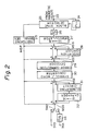
- Figure 2 shows a reproduction apparatus including mode selection switches MS6 to MS9.
- mode selection switches MS6 to MS9 the terminal A sides are selected in the A mode and terminal B sides are selected in the B mode under the control of a mode selection signal MDP.
- Reproduction data from an input terminal 22 is supplied to a block-synchronization-signal detector 23 and a phase locked loop (PLL) circuit 24.
- a clock signal in synchronism with the reproduction data is developed by the PLL circuit 24, the clock signal is fed to the block-synchronization-signal detector 23, and the block synchronization signal is supplied to a switching signal generator 25.
- the mode selection signal MDP is formed by the switching signal generator 25.
- the reproduction data are supplied to a serial-parallel converter 26 and converted into 10-bit parallel data.
- the output signal of the serial-parallel converter 26 is supplied to a ten-to-eight demodulator 27 so that a 10-bit to 8-bit conversion is made.
- the ten-to-eight demodulator 27 is complementary with the eight-to-ten modulator 17 on the recording side and is made up of a ROM (not shown) storing a data conversion map.
- the output signal of the ten-to-eight demodulator 17 is supplied to an error correction decoder 29 through the terminal A side of the mode selection switch MS6 and the terminal A side of the mode selection switch MS7.
- the output signal of the ten-to-eight demodulator 27 is supplied to a dummy bit insertion circuit 28 through the mode selection switch MS6.
- the dummy bit insertion circuit 28 dummy bits are inserted in the positions in the block similar to those at the time of recording. Even in the case of 12-bit data, the size of the block is kept equal to 16-bit data.
- the output signal of the dummy bit insertion circuit 28 is supplied to the error correction decoder 29 through the terminal B side of the mode selection switch MS7.
- the error correction decoder 29 is used in common with the 16-bit data and 12-bit data.
- the error correction decoder 29 has a memory (not shown) for storing one block of data, and the decoding of the C1 code and the C2 code is made using reproduced data read out from the memory.
- the time axis is expanded by a factor of six by the error correction decoder 29.
- the error corrected data from the error correction decoder 29 are fed to a symbol/word converter 30 for a symbol to word conversion.
- the output signal of the symbol/word converter 30 is supplied to a switch circuit SW2 through the terminal A of the mode selection switch MS8 and the terminal A of the mode selection switch MS9.
- the output signal of the symbol/word converter 30 is supplied to a dummy bit elimination circuit 31 through the terminal B side of the mode selection switch MS8.
- the output signal of the dummy bit elimination circuit 31 is supplied to a 12 to 16-bit expanding circuit 32 for the expansion of one word to sixteen bits.
- the output signal of the 12 to 16-bit expanding circuit 32 is supplied to the switch circuit SW2 through the terminal B of the mode selection switch MS9.
- an interpolation circuit can be provided at the decoder 29 to interpolate a word which cannot be error-corrected using a plurality of correct words.
- rotary heads HA and HB provide different azimuth angles by having their operation gaps disposed at 180 o to one another.
- the rotary heads HA and HB are rotated in the direction indicated by an arrow 3H at a frame frequency.
- a magnetic tape 2 is run at constant speed in the direction of an arrow 3T while wound around the circumferential surface of a drum 1 containing the heads HA and HB over an angular range of 221 o .
- Tracks 4A and 4B having a length corresponding to 221 o are alternately formed on the tape 2 by the rotary heads HA and HB, as shown in Figure 4.
- a digital audio signal related to one field of a video signal is recorded as compressed in terms of the time axis.
- a colour video signal of one field, an FM audio signal and a pilot signal for tracking of the rotary heads HA and HB are recorded by frequency multiplexing. The remaining 5 o is provided for a margin for the separation of the rotary head HA and HB from the tape 2.
- the recording area AV for the colour video signal can also be used as a recording area for a PCM audio signal, when the 8mm VTR is used as a recording/reproducing divide for audio only.
- the length of the area AV having an angular range of 180 o in which the colour video signal is recorded is five times as long as that of the area AP having an angular range of 36 o
- five area AP2 to AP6 can be provided for each track 4A and 4B besides the original area AP1, as shown in Figure 5.
- Digital audio signals of different channels are recorded in these six areas AP1 to AP6.
- Figures 6 and 7 show respective block structures of the NTSC system and the CCIR system in the A mode (one word has six bits).
- symbols of data are disposed in a matrix form of 36 x 90.
- the total number of symbols is 3240.
- the number of symbols of audio data which are actually used is 3204 symbols, and the remaining 36 symbols are reserve data.
- a header signal of 4 x 110 symbols is added.
- the header signal is added to the adder 18 after the encoding of the error correction code has been performed. In this structure, the header signal is not error encoded.
- the encoding of the C1 code is done when necessary with respect to the address signal and the various identification signals (that is, signals of block-in addresses 0 to 3) other than the synchronization signal (one symbol lying in the first row) of the header signal.
- the encoding of the C1 code is made for every 39 symbols, which are the sum of three symbols of the header signal arranged in the vertical direction and 36 symbols of data.
- the C1 code is a Reed-Solomon code (43, 39, 5), that is, whose code length, information length and distance are, respectively, 43, 39, 5.
- a four symbol redundant code P (hereunder called 'check data') of the C1 code is developed for every set of 39 symbols and is disposed at each of four rows on the lower side of the block.
- the encoding of the C2 code is carried out in the horizontal direction of the block.
- the C2 code is a Reed-Solomon code of code length, information length and distance are, respectively, 22, 18, 5. 90 symbols are contained in each row in the horizontal direction of the block.
- a block of size of 44 x 110 is finally provided based on the audio data, reserve data, header signal, and check data P, Q.
- the above-mentioned generating method of P and Q parities is similar to the technique disclosed in detail in US patent specification US-A-4 688 225 and US patent application serial no 252 807. Recording onto magnetic tape is done by reading the data from each block sequentially (from the block address 0 towards the block address 109 for every 44 symbols arranged in the vertical direction.
- words of an even number are disposed on one side of a block (on the left-hand side in the drawing) when numbers are attached from the first word, words of an odd number are arranged on the other side of the block (on the right-hand side in the drawing), and check data of the C2 code is disposed between data of an even number and data of an odd number. This is to prevent the recording positions of audio data which is continuous in terms of time from separating on the magnetic tape to become error data.
- the encoding of the C1 code is made for check data Q of the C2 code to develop check data P.
- the check data provided at this time is identical to check data Q provided when the encoding of the C2 code is done for check data P of the C1 code.
- P (Q) code is used in the drawings.
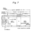
- the process of the encoding is done using a block structure shown in Figure 7.
- symbols of data are arranged in a matrix fashion of 36 x 108.
- the total number of symbols (44 symbols) in the vertical direction is equal to the block in the NTSC system shown in Figures 6A and 6B.
- the total number of symbols becomes 3888.
- Audio data are 3840 symbols, and the remaining 48 symbols are reserve data.
- a header signal of 4 x 132 symbols is added.
- the encoding of the C1 code is carried out for every 39 symbols, that is, equal to the sum of three symbols of the header signal and 36 symbols of the data arranged in the vertical direction.
- the C1 code is a Reed-Solomon code of (43, 39, 5) similar to the NTSC system.
- Check data P for a 4-symbol C1 code is developed for every set of 39 symbols and disposed in four rows on the lower side of the block.
- the encoding of the C2 code is executed in the horizontal direction of the block.
- a block having the size of 44 x 132 symbols is finally provided by audio data, reserve data, the header signal and check data P, Q.
- the recording is made in the order of every 44 symbols arranged in the vertical direction at the time of recording.
- the arrangement of words of an even number, words of an odd number and check data of the C2 code is similar to Figures 6A and 6B.
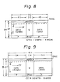
- FIG. 8 and 9 show the block diagrams in the case where the input signal to the dummy bit insertion circuit 13 is assumed to be input to the error correction encoder 15.
- the same codes can be employed for the C1 code and the C2 code for the A mode and the B mode, and the error correction encoder 15 can be used in common with the two modes.
- the same C1 code and C2 code can be used in the NTSC system and CCIR system except for the size of the block and the interleave length in the horizontal direction.
- Figure 10A, 10B and 10C show an enlarged part of the block in the A mode (NTSC system) shown in Figures 6A and 6B.
- Data L0, L1, L2, ... of one channel (left-hand channel) of 16-bit word data and data R0, R1, R2, ... of the other channel (right-hand channel) are divided into upper 8-bit symbols (code u is affixed) and lower 8-bit symbols (code 1 is affixed). For instance, one word L0 is divided into two symbols L 0,u and L 0,1 .
- a header signal (strictly speaking, a synchronization signal is excluded) is added and supplied to the error correction encoder, and check data P of the C1 code and check data Q (not shown) of the C2 code are added.
- Data indicated in Figure 10C similar to Figure 10B is recorded onto a magnetic tape.
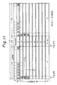
- dummy data is added to form a block shown in Figure 11.
- data shaded by oblique lines is the dummy data (zero data).
- dummy data of one symbol is added on the lower side of a header signal for three symbols in the vertical direction.
- the size of the block becomes equal to that in the A mode. Since the dummy data are arranged in the horizontal direction, a part of check data Q of the C2 code is developed only from dummy data. The check data that are developed from the dummy data only are indicated by cross hatching in Figure 11.
- Figures 12A, 12B, 12C, 12D and 12E are for explaining the addition of dummy data.
- Figure 12A shows a state in which one word of 12-bit data has been converted into symbols each having an 8-bit length.
- the upper eight bits of the twelve bits are selected to be an upper side symbol (u code is attached), and the lower four bits are assigned a lower-side symbol (1 code is attached). With such word to symbol conversion, a 4-bit vacancy occurs on the right-hand side of the lower symbol.
- the lower four bits of another word are inserted into the vacancy, and dummy data (eight bits) are inserted into the 8-bit vacancy occurring in the position previously occupied in part by the moved lower four bits.
- dummy data (eight bits) are inserted into the 8-bit vacancy occurring in the position previously occupied in part by the moved lower four bits.
- a symbol R 0,1 is disposed in a vacancy occurring on the right-hand side of a symbol L 0,1
- dummy data are inserted into the place where the symbol R 0,1 had been positioned. Therefore, in Figure 12B, as shown by an oblique line, one symbol of dummy data is added after each group of three symbols of real data when one column in the block is viewed. Since dummy data are inserted into all columns in this manner, the dummy data are consequently arranged in the horizontal direction. in this way, the encoding of the C2 code and the C1 code is performed in the state where dummy data are added.
- the dummy data are excluded at the dummy bit elimination circuit 16 after the encoding, and data from which the dummy data has ben eliminated are recorded onto a magnetic tape. Since the dummy data are arranged as stated above, redundant check data (that is, zero data) of the C2 code developed from the dummy data as indicated by a cross hatching in Figure 12D occurs at three symbol intervals even in the set of check data of the C2 code. The check data developed only from the dummy data are eliminated, and check data Q shown in Figure 12E is transmitted and recorded onto a magnetic tape.
- dummy data are added by first writing zero data into a memory of an error correction encoder in advance and then writing symbols so as to provide the array indicated in Figure 12B.
- processing similar to the above-mentioned addition of dummy data in the NTSC system is applicable to the CCIR system.
- the sizes of the blocks between the A mode and the B mode can be kept equal.
- the invention is also applicable to the case where the sizes of the blocks are kept equal in the NTSC system and the CCIR system in the same mode.
- the sizes in the horizontal direction (NTSC system: 110, CCIR system: 132) between the NTSC system and the CCIR system are different, as seen from Figures 6 and 7.
- a block of the same size as in the CCIR system can be constructed.
- Figure 15 shows one example to attain this object.
- one symbol of dummy data are added at intervals of five symbols with respect to the block shown in Figures 6A and 6B in the NTSC system so that the data are arranged in the vertical direction.
- the interleave length of the C2 code in the horizontal direction is selected to be six, and, therefore, check data Q of the C2 code consisting of only the dummy data are developed.
- check data P of the C1 code are developed from dummy data arranged in the vertical direction.
- these dummy data and check data P, Q of the C1 code and the C2 code are eliminated.
- the dummy data can be arranged in a lump on the left-hand side or on the right-hand side of the block.
- both of the above-mentioned first embodiment (the system in which the sizes of the blocks are kept equal between the A mode and the B mode) and the second embodiment (the system in which the sizes of the blocks are kept equal in the NTSC system and the CCIR system) can be combined.
- dummy data are to be added to the smaller data block so that its size is matched to the largest block of the four combinations ( Figures 6A and 6B to 9) and the dummy data are arranged in the horizontal direction or in the vertical direction. With such an arrangement, the block size is unified, and the interleave length of the C2 code in the horizontal direction is unified.
- predetermined data can be employed without being limited to zero data.
- the sizes of the blocks of error correction codes become equal, despite the difference of the bit numbers of words and the difference of television systems, and each of the encoder and the decoder for the error correction coding and decoding can be the same for the different modes and between different television systems.
- the amount of hardware required is small.
- a part of the error correction code check data is composed of dummy data only. For this reason, not only the transmission of dummy data but also the transmission of a part of the check data can be omitted to lower the data amount for transmission. Consequently, the rate of transmission of the data can be reduced.
Landscapes
- Engineering & Computer Science (AREA)
- Multimedia (AREA)
- Signal Processing (AREA)
- Signal Processing For Digital Recording And Reproducing (AREA)
- Detection And Prevention Of Errors In Transmission (AREA)
Applications Claiming Priority (2)
| Application Number | Priority Date | Filing Date | Title |
|---|---|---|---|
| JP63156566A JP2638091B2 (ja) | 1988-06-24 | 1988-06-24 | データ伝送方法 |
| JP156566/88 | 1988-06-24 |
Publications (3)
| Publication Number | Publication Date |
|---|---|
| EP0348132A2 true EP0348132A2 (de) | 1989-12-27 |
| EP0348132A3 EP0348132A3 (en) | 1990-12-05 |
| EP0348132B1 EP0348132B1 (de) | 1994-09-14 |
Family
ID=15630584
Family Applications (1)
| Application Number | Title | Priority Date | Filing Date |
|---|---|---|---|
| EP89306190A Expired - Lifetime EP0348132B1 (de) | 1988-06-24 | 1989-06-19 | Verfahren und Gerät zur Übertragung von Daten |
Country Status (6)
| Country | Link |
|---|---|
| US (1) | US4972417A (de) |
| EP (1) | EP0348132B1 (de) |
| JP (1) | JP2638091B2 (de) |
| CA (1) | CA1315874C (de) |
| DE (1) | DE68918173T2 (de) |
| ES (1) | ES2058529T3 (de) |
Cited By (9)
| Publication number | Priority date | Publication date | Assignee | Title |
|---|---|---|---|---|
| EP0470792A1 (de) * | 1990-08-06 | 1992-02-12 | Matsushita Electric Industrial Co., Ltd. | Verfahren zur Aufzeichnung digitaler Signale |
| EP0408754A4 (en) * | 1988-10-24 | 1992-07-22 | Matsushita Electric Industrial Co., Ltd. | Interframe deinterlave switching circuit |
| EP0522869A3 (de) * | 1991-07-11 | 1994-03-02 | Sony Corp | |
| EP0601566A1 (de) * | 1992-12-11 | 1994-06-15 | Sony Corporation | Gerät und Verfahren zur Digitalsignalverarbeitung und Aufzeichnungsmedium |
| US5590108A (en) * | 1993-05-10 | 1996-12-31 | Sony Corporation | Encoding method and apparatus for bit compressing digital audio signals and recording medium having encoded audio signals recorded thereon by the encoding method |
| US5717821A (en) * | 1993-05-31 | 1998-02-10 | Sony Corporation | Method, apparatus and recording medium for coding of separated tone and noise characteristic spectral components of an acoustic sibnal |
| US5765126A (en) * | 1993-06-30 | 1998-06-09 | Sony Corporation | Method and apparatus for variable length encoding of separated tone and noise characteristic components of an acoustic signal |
| US5825979A (en) * | 1994-12-28 | 1998-10-20 | Sony Corporation | Digital audio signal coding and/or deciding method |
| EP0680043A3 (de) * | 1994-04-26 | 1999-04-28 | Nec Corporation | Plattensteuerung |
Families Citing this family (42)
| Publication number | Priority date | Publication date | Assignee | Title |
|---|---|---|---|---|
| JP3137119B2 (ja) * | 1989-06-07 | 2001-02-19 | キヤノン株式会社 | 誤り訂正装置 |
| US6002536A (en) * | 1990-07-06 | 1999-12-14 | Hitachi Ltd. | Digital transmission signal processing system and recording/reproducing system |
| US5517368A (en) * | 1990-07-06 | 1996-05-14 | Hitachi, Ltd. | Digital transmission signal processing system and recording/reproducing system |
| US5289476A (en) * | 1991-05-10 | 1994-02-22 | Echelon Corporation | Transmission mode detection in a modulated communication system |
| JPH04358486A (ja) * | 1991-06-04 | 1992-12-11 | Toshiba Corp | 高能率符号化信号処理装置 |
| JPH0562363A (ja) * | 1991-08-30 | 1993-03-12 | Victor Co Of Japan Ltd | 記録再生方法 |
| US5574570A (en) * | 1992-05-12 | 1996-11-12 | Mitsubishi Denki Kabushiki Kaisha | Video signal recording/reproduction apparatus and method for recording/reproducing two kinds of video signals carrying different amounts of information |
| EP0571096B1 (de) * | 1992-05-18 | 1999-06-23 | Canon Kabushiki Kaisha | Datenverarbeitungsvorrichtung |
| JP3250260B2 (ja) * | 1992-06-17 | 2002-01-28 | ソニー株式会社 | 画像データ記録装置及び画像データ再生装置 |
| US5493574A (en) * | 1992-09-24 | 1996-02-20 | Zilog, Inc. | Power efficient RAM disk and a method of emulating a rotating memory disk |
| JPH06195884A (ja) * | 1992-10-30 | 1994-07-15 | Sony Corp | 磁気記録再生装置 |
| US5428627A (en) * | 1992-11-10 | 1995-06-27 | Qlogic Corporation | Method and apparatus for initializing an ECC circuit |
| JP2885263B2 (ja) * | 1993-09-30 | 1999-04-19 | 日本ビクター株式会社 | 符号生成方法 |
| JP3480057B2 (ja) * | 1994-09-12 | 2003-12-15 | ソニー株式会社 | データ記録方法、データ再生方法及び記録媒体 |
| JP3234130B2 (ja) * | 1995-05-30 | 2001-12-04 | 三菱電機株式会社 | 誤り訂正符号復号化方法およびこの方法を用いる回路 |
| US5717951A (en) * | 1995-08-07 | 1998-02-10 | Yabumoto; Kan W. | Method for storing and retrieving information on a magnetic storage medium via data blocks of variable sizes |
| US5835502A (en) * | 1996-06-28 | 1998-11-10 | International Business Machines Corporation | Method and apparatus for handling variable data word widths and array depths in a serial shared abist scheme |
| EP0840517A3 (de) * | 1996-10-31 | 2003-09-10 | Matsushita Electric Industrial Co., Ltd. | Videodatenstromdekodierungsverfahren und -vorrichtung |
| JP3147078B2 (ja) * | 1998-04-06 | 2001-03-19 | 日本電気株式会社 | Fec符号語のダミービット除去装置及び符号化装置 |
| EP1098467A1 (de) * | 1999-11-08 | 2001-05-09 | THOMSON multimedia | Verfahren un Vorrichtung zum Initialisieren einer Faltungsentschachtelung sowie einer Faltungsverschachtelung |
| KR20010081335A (ko) * | 2000-02-12 | 2001-08-29 | 구자홍 | 차세대 고밀도 기록 매체를 위한 디지털 데이터의 오류정정 부호화 방법 |
| JP2003318865A (ja) * | 2002-04-26 | 2003-11-07 | Fuji Xerox Co Ltd | 信号伝送システム |
| US7111228B1 (en) | 2002-05-07 | 2006-09-19 | Marvell International Ltd. | System and method for performing parity checks in disk storage system |
| US7287102B1 (en) | 2003-01-31 | 2007-10-23 | Marvell International Ltd. | System and method for concatenating data |
| US7007114B1 (en) | 2003-01-31 | 2006-02-28 | Qlogic Corporation | System and method for padding data blocks and/or removing padding from data blocks in storage controllers |
| US7492545B1 (en) | 2003-03-10 | 2009-02-17 | Marvell International Ltd. | Method and system for automatic time base adjustment for disk drive servo controllers |
| US7039771B1 (en) | 2003-03-10 | 2006-05-02 | Marvell International Ltd. | Method and system for supporting multiple external serial port devices using a serial port controller in embedded disk controllers |
| US7064915B1 (en) | 2003-03-10 | 2006-06-20 | Marvell International Ltd. | Method and system for collecting servo field data from programmable devices in embedded disk controllers |
| US7870346B2 (en) | 2003-03-10 | 2011-01-11 | Marvell International Ltd. | Servo controller interface module for embedded disk controllers |
| US7219182B2 (en) | 2003-03-10 | 2007-05-15 | Marvell International Ltd. | Method and system for using an external bus controller in embedded disk controllers |
| US7526691B1 (en) | 2003-10-15 | 2009-04-28 | Marvell International Ltd. | System and method for using TAP controllers |
| US7139150B2 (en) | 2004-02-10 | 2006-11-21 | Marvell International Ltd. | Method and system for head position control in embedded disk drive controllers |
| US7120084B2 (en) | 2004-06-14 | 2006-10-10 | Marvell International Ltd. | Integrated memory controller |
| US8166217B2 (en) | 2004-06-28 | 2012-04-24 | Marvell International Ltd. | System and method for reading and writing data using storage controllers |
| US8032674B2 (en) | 2004-07-19 | 2011-10-04 | Marvell International Ltd. | System and method for controlling buffer memory overflow and underflow conditions in storage controllers |
| US7757009B2 (en) | 2004-07-19 | 2010-07-13 | Marvell International Ltd. | Storage controllers with dynamic WWN storage modules and methods for managing data and connections between a host and a storage device |
| US9201599B2 (en) | 2004-07-19 | 2015-12-01 | Marvell International Ltd. | System and method for transmitting data in storage controllers |
| US7386661B2 (en) | 2004-10-13 | 2008-06-10 | Marvell International Ltd. | Power save module for storage controllers |
| US7240267B2 (en) | 2004-11-08 | 2007-07-03 | Marvell International Ltd. | System and method for conducting BIST operations |
| US7802026B2 (en) | 2004-11-15 | 2010-09-21 | Marvell International Ltd. | Method and system for processing frames in storage controllers |
| US7609468B2 (en) | 2005-04-06 | 2009-10-27 | Marvell International Ltd. | Method and system for read gate timing control for storage controllers |
| US12142333B2 (en) * | 2022-04-04 | 2024-11-12 | Micron Technology, Inc. | Error correction in a memory device having an error correction code of a predetermined code rate |
Family Cites Families (7)
| Publication number | Priority date | Publication date | Assignee | Title |
|---|---|---|---|---|
| US4320511A (en) * | 1979-03-13 | 1982-03-16 | Kokusai Denshin Denwa Co., Ltd. | Method and device for conversion between a cyclic and a general code sequence by the use of dummy zero bit series |
| JPS57207960A (en) * | 1981-06-17 | 1982-12-20 | Toshiba Corp | Method for adding error correcting code to variable length data |
| JPS58222402A (ja) * | 1982-02-02 | 1983-12-24 | Sony Corp | 情報信号の記録装置 |
| JPH0661156B2 (ja) * | 1983-05-21 | 1994-08-10 | ソニー株式会社 | エラ−訂正のための符号化方法 |
| JP2574744B2 (ja) * | 1985-04-10 | 1997-01-22 | 株式会社日立製作所 | Pcm信号記録再生装置 |
| KR900008446B1 (ko) * | 1985-11-13 | 1990-11-22 | 가부시끼가이샤 히다찌세이사꾸쇼 | 음성신호를위한표본화주파수와회전헤드스캔너의회전주파수사이에서비동기관계를갖는음성신호의pcm기록재생장치 |
| JP2751201B2 (ja) * | 1988-04-19 | 1998-05-18 | ソニー株式会社 | データ伝送装置及び受信装置 |
-
1988
- 1988-06-24 JP JP63156566A patent/JP2638091B2/ja not_active Expired - Lifetime
-
1989
- 1989-06-15 US US07/366,751 patent/US4972417A/en not_active Expired - Lifetime
- 1989-06-19 EP EP89306190A patent/EP0348132B1/de not_active Expired - Lifetime
- 1989-06-19 DE DE68918173T patent/DE68918173T2/de not_active Expired - Lifetime
- 1989-06-19 CA CA000603235A patent/CA1315874C/en not_active Expired - Lifetime
- 1989-06-19 ES ES89306190T patent/ES2058529T3/es not_active Expired - Lifetime
Cited By (11)
| Publication number | Priority date | Publication date | Assignee | Title |
|---|---|---|---|---|
| EP0408754A4 (en) * | 1988-10-24 | 1992-07-22 | Matsushita Electric Industrial Co., Ltd. | Interframe deinterlave switching circuit |
| EP0470792A1 (de) * | 1990-08-06 | 1992-02-12 | Matsushita Electric Industrial Co., Ltd. | Verfahren zur Aufzeichnung digitaler Signale |
| EP0522869A3 (de) * | 1991-07-11 | 1994-03-02 | Sony Corp | |
| US5504759A (en) * | 1991-07-11 | 1996-04-02 | Sony Corporation | Digital signal recording and/or reproducing apparatus using a common processing device for digital signals having different data configurations |
| EP0601566A1 (de) * | 1992-12-11 | 1994-06-15 | Sony Corporation | Gerät und Verfahren zur Digitalsignalverarbeitung und Aufzeichnungsmedium |
| US5490130A (en) * | 1992-12-11 | 1996-02-06 | Sony Corporation | Apparatus and method for compressing a digital input signal in more than one compression mode |
| US5590108A (en) * | 1993-05-10 | 1996-12-31 | Sony Corporation | Encoding method and apparatus for bit compressing digital audio signals and recording medium having encoded audio signals recorded thereon by the encoding method |
| US5717821A (en) * | 1993-05-31 | 1998-02-10 | Sony Corporation | Method, apparatus and recording medium for coding of separated tone and noise characteristic spectral components of an acoustic sibnal |
| US5765126A (en) * | 1993-06-30 | 1998-06-09 | Sony Corporation | Method and apparatus for variable length encoding of separated tone and noise characteristic components of an acoustic signal |
| EP0680043A3 (de) * | 1994-04-26 | 1999-04-28 | Nec Corporation | Plattensteuerung |
| US5825979A (en) * | 1994-12-28 | 1998-10-20 | Sony Corporation | Digital audio signal coding and/or deciding method |
Also Published As
| Publication number | Publication date |
|---|---|
| EP0348132B1 (de) | 1994-09-14 |
| DE68918173T2 (de) | 1995-01-19 |
| US4972417A (en) | 1990-11-20 |
| ES2058529T3 (es) | 1994-11-01 |
| EP0348132A3 (en) | 1990-12-05 |
| JP2638091B2 (ja) | 1997-08-06 |
| DE68918173D1 (de) | 1994-10-20 |
| JPH027274A (ja) | 1990-01-11 |
| CA1315874C (en) | 1993-04-06 |
Similar Documents
| Publication | Publication Date | Title |
|---|---|---|
| EP0348132B1 (de) | Verfahren und Gerät zur Übertragung von Daten | |
| EP0303450B1 (de) | Digital-Signal-Übertragungseinrichtung | |
| US4975915A (en) | Data transmission and reception apparatus and method | |
| EP0542576B1 (de) | Vorrichtung und Verfahren zum Aufnehmen und Wiedergeben von digitalen Video- und Audiosignalen | |
| US5583707A (en) | Digital video tape recorder with data block I.D. signal error correction | |
| US4630272A (en) | Encoding method for error correction | |
| US5172380A (en) | Digital signal transmission apparatus | |
| CA1250661A (en) | Apparatus for recording and/or reproducing digital information signal | |
| CA1298403C (en) | Method and apparatus for pcm recording and reproducing audio signal | |
| US4819088A (en) | Magnetic recording and reproducing system | |
| EP0492704B1 (de) | Anordnung zum Aufzeichnen von Takteinlauf-Codewörtern in einer Spur auf einem magnetischen Aufzeichnungsträger | |
| GB2065416A (en) | Apparatus for recording digital video signals | |
| US20020009292A1 (en) | Signal recording apparatus | |
| EP0349325A2 (de) | Gerät zur Uebertragung eines digitalen Signals | |
| US4928185A (en) | Rotary head type recording/reproducing method and apparatus for recording and reproducing a digital audio signal | |
| EP0315372A2 (de) | Aufzeichnungsgerät für digitale Signale | |
| US5101274A (en) | Digital signal recording apparatus time-division multiplexing video and audio signals | |
| EP0437316B1 (de) | Aufzeichnungsverfahren für digitale Signale und Gerät zur Aufzeichnung und Wiedergabe digitaler Signale | |
| EP0366402B1 (de) | Verfahren zur Aufzeichnung/Wiedergabe eines digitalen Audiosignals und mitgehende Einrichtung | |
| KR0127909B1 (ko) | 데이타 전송 장치 | |
| US6192182B1 (en) | Digital information signal recording apparatus and method thereof | |
| US6349012B1 (en) | Magnetic recording and/or reproducing apparatus | |
| JPH0690859B2 (ja) | ディジタル情報信号の処理方法 | |
| JP3259298B2 (ja) | ディジタル画像信号の記録装置 |
Legal Events
| Date | Code | Title | Description |
|---|---|---|---|
| PUAI | Public reference made under article 153(3) epc to a published international application that has entered the european phase |
Free format text: ORIGINAL CODE: 0009012 |
|
| AK | Designated contracting states |
Kind code of ref document: A2 Designated state(s): DE ES FR GB NL |
|
| PUAL | Search report despatched |
Free format text: ORIGINAL CODE: 0009013 |
|
| AK | Designated contracting states |
Kind code of ref document: A3 Designated state(s): DE ES FR GB NL |
|
| 17P | Request for examination filed |
Effective date: 19910313 |
|
| 17Q | First examination report despatched |
Effective date: 19930216 |
|
| GRAA | (expected) grant |
Free format text: ORIGINAL CODE: 0009210 |
|
| AK | Designated contracting states |
Kind code of ref document: B1 Designated state(s): DE ES FR GB NL |
|
| REF | Corresponds to: |
Ref document number: 68918173 Country of ref document: DE Date of ref document: 19941020 |
|
| REG | Reference to a national code |
Ref country code: ES Ref legal event code: FG2A Ref document number: 2058529 Country of ref document: ES Kind code of ref document: T3 |
|
| ET | Fr: translation filed | ||
| PLBE | No opposition filed within time limit |
Free format text: ORIGINAL CODE: 0009261 |
|
| STAA | Information on the status of an ep patent application or granted ep patent |
Free format text: STATUS: NO OPPOSITION FILED WITHIN TIME LIMIT |
|
| 26N | No opposition filed | ||
| REG | Reference to a national code |
Ref country code: GB Ref legal event code: IF02 |
|
| PGFP | Annual fee paid to national office [announced via postgrant information from national office to epo] |
Ref country code: DE Payment date: 20080626 Year of fee payment: 20 Ref country code: NL Payment date: 20080603 Year of fee payment: 20 Ref country code: ES Payment date: 20080717 Year of fee payment: 20 |
|
| PGFP | Annual fee paid to national office [announced via postgrant information from national office to epo] |
Ref country code: FR Payment date: 20080617 Year of fee payment: 20 |
|
| PGFP | Annual fee paid to national office [announced via postgrant information from national office to epo] |
Ref country code: GB Payment date: 20080625 Year of fee payment: 20 |
|
| REG | Reference to a national code |
Ref country code: GB Ref legal event code: PE20 Expiry date: 20090618 |
|
| PG25 | Lapsed in a contracting state [announced via postgrant information from national office to epo] |
Ref country code: NL Free format text: LAPSE BECAUSE OF EXPIRATION OF PROTECTION Effective date: 20090619 |
|
| NLV7 | Nl: ceased due to reaching the maximum lifetime of a patent |
Effective date: 20090619 |
|
| REG | Reference to a national code |
Ref country code: ES Ref legal event code: FD2A Effective date: 20090620 |
|
| PG25 | Lapsed in a contracting state [announced via postgrant information from national office to epo] |
Ref country code: ES Free format text: LAPSE BECAUSE OF EXPIRATION OF PROTECTION Effective date: 20090620 |
|
| PG25 | Lapsed in a contracting state [announced via postgrant information from national office to epo] |
Ref country code: GB Free format text: LAPSE BECAUSE OF EXPIRATION OF PROTECTION Effective date: 20090618 |