EP0348711B1 - Dispositif de déplacement axial des cylindres dans la cage d'un laminoir - Google Patents
Dispositif de déplacement axial des cylindres dans la cage d'un laminoir Download PDFInfo
- Publication number
- EP0348711B1 EP0348711B1 EP89110436A EP89110436A EP0348711B1 EP 0348711 B1 EP0348711 B1 EP 0348711B1 EP 89110436 A EP89110436 A EP 89110436A EP 89110436 A EP89110436 A EP 89110436A EP 0348711 B1 EP0348711 B1 EP 0348711B1
- Authority
- EP
- European Patent Office
- Prior art keywords
- bearing
- axial
- stand
- rolls
- roller
- Prior art date
- Legal status (The legal status is an assumption and is not a legal conclusion. Google has not performed a legal analysis and makes no representation as to the accuracy of the status listed.)
- Expired - Lifetime
Links
- 238000005096 rolling process Methods 0.000 title claims abstract description 21
- 238000006073 displacement reaction Methods 0.000 claims description 25
- 238000005097 cold rolling Methods 0.000 claims description 3
- 238000005098 hot rolling Methods 0.000 claims description 3
- 238000005265 energy consumption Methods 0.000 abstract 1
- 230000033001 locomotion Effects 0.000 description 4
- 238000010276 construction Methods 0.000 description 2
- 238000007789 sealing Methods 0.000 description 2
- 230000005540 biological transmission Effects 0.000 description 1
- 238000011109 contamination Methods 0.000 description 1
- 239000000428 dust Substances 0.000 description 1
- 238000012423 maintenance Methods 0.000 description 1
- 239000000463 material Substances 0.000 description 1
Images
Classifications
-
- B—PERFORMING OPERATIONS; TRANSPORTING
- B21—MECHANICAL METAL-WORKING WITHOUT ESSENTIALLY REMOVING MATERIAL; PUNCHING METAL
- B21B—ROLLING OF METAL
- B21B31/00—Rolling stand structures; Mounting, adjusting, or interchanging rolls, roll mountings, or stand frames
- B21B31/16—Adjusting or positioning rolls
- B21B31/18—Adjusting or positioning rolls by moving rolls axially
-
- B—PERFORMING OPERATIONS; TRANSPORTING
- B21—MECHANICAL METAL-WORKING WITHOUT ESSENTIALLY REMOVING MATERIAL; PUNCHING METAL
- B21B—ROLLING OF METAL
- B21B31/00—Rolling stand structures; Mounting, adjusting, or interchanging rolls, roll mountings, or stand frames
- B21B31/07—Adaptation of roll neck bearings
Definitions
- the invention relates to a device for the axial displacement of rolls in the stand of a rolling mill according to the preamble of claim 1; See GB-A 2 024 454.
- axial displacements of the rolls, especially the work rolls are necessary . Therefore, as can be seen, for example, from DE-OS 35 21 180, a device for the axial displacement of rolls in roll stands has been designed, in which the rolls are held in special chocks via their radial and axial bearings, which in turn are held in the roll stands of the rolling stand arranged sliding guides and sliding carriages are slidably guided.
- the chocks hydraulic piston-cylinder units articulated, which are attached to the outside of the roll stand.
- FIG. 4 shows that the bearing chock is fixed in the frame and the inner bearing ring of the radial bearing, which is designed as a roller bearing and is attached to the bearing journal of the roller, is axially movable relative to the outer bearing ring of the radial bearing or vice versa.
- the thrust bearing is very complicated with a large number of individual actuators arranged within its housing, which leads to the fact that these, including the integrated displacement sensors, are extremely difficult to access and difficult to maintain.
- the object of the invention is to provide a device for the axial displacement of rolls in a stand of a rolling mill, which is free from these known disadvantages mentioned above and is particularly characterized by its very simple construction and easy access to the hydraulic and mechanical components.
- the axial forces to be applied by the displacement system for axially displacing the roller can therefore be kept lower in the bearing system on which the invention is based in comparison with roller displacement devices with axially displaceable chocks, and energy and costs can thereby be saved, in particular if, as in the arrangement on which the invention is based, the displacement system as a hydraulic pressure system in Thrust bearing is integrated.
- the hydraulic pressure system integrated in the axial bearing consists of a double-acting piston-cylinder unit, the outer bearing ring of the axial bearing is designed as a piston and the bearing housing surrounding it is designed as a cylinder.
- the outer bearing ring designed as a piston and the bearing housing of the axial bearing designed as a cylinder are made in several parts. In this way, the maintenance and replacement of the bearing or the hydraulic pressure system or parts thereof considerably relieved.
- the radial bearings are, according to a further advantageous embodiment of the invention, with several, in rows in the axial direction at a distance bearing bodies arranged from each other. It is also particularly expedient to use a cylindrical roller bearing or a radial bearing designed as a needle roller bearing.
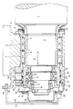
- the drawing shows a section of a roller (1) of a rolling mill with a bearing journal (2) which is tapered in a step-like manner at the left end and is mounted in a radial bearing (3) and an axial bearing (4) shown in longitudinal section.
- the right end of the roller (1) which is not shown in the drawing, is provided with a single-stage bearing journal which is mounted in a radial bearing of the same design as the radial bearing (3).
- These radial bearings (3) consist of an inner, relatively long, attached to the bearing journal (2) trained bearing ring (5) and two outer bearing rings (7, 8) arranged in the stand (6) of the rolling mill and from the intermediate bearing bodies (9) arranged in four rows at a distance from one another.
- This inventive design of the radial bearing (3) very advantageously allows an axial displacement (arrows 10) of the roller (1) together with the inner bearing ring (5) relative to the outer, two-part bearing ring (7, 8) without it to the undesirably disadvantageous, energy-consuming sliding friction between the bearing rings (5) and (7, 8), since the axial movement of the inner bearing ring (5) relative to the outer bearing ring (7, 8) is absorbed by the bearing bodies (9) and into one Rolling motion is converted from very little friction.
- the radial bearings (3) are expediently designed as cylindrical roller bearings in order to be able to reliably absorb and compensate for the high loads occurring on the rollers during operation of the rolling mill.
- other roller bearings such as needle roller bearings, barrel roller bearings, etc. in a single or multi-row arrangement can also advantageously be used as radial bearings.
- the axial bearing (4) with integrated hydraulic bearings which is also shown in longitudinal section in the drawing and is arranged on the left-hand side and is firmly connected to the stepped bearing journal (2) Printing system provided.
- This axial bearing (4) consists of an inner bearing ring (11) attached to the bearing journal (2), which counteracts axial displacement on the journal (2) is secured by support and retaining rings (12, 13, 14, 15), and from an outer bearing ring (16) with intermediate support rings (17) and bearing rollers (18).
- the outer bearing roller support ring (17) is supported in the axial direction by a ring (19) with a flange which is firmly connected to the outer bearing ring (16).
- the outer bearing ring (16) of the axial bearing (4) is provided on the outside with an annular extension (20) with a sealing ring (21) which is slidably guided in an axially movable manner in a cylindrical recess (22) of the bearing housing (23).
- an annular disc (24) with a sealing ring (25) is attached, which seals the cylindrical recess (22) in the bearing housing (23) to the outside in a pressure-tight manner.
- the axial displacement path of the roller (1) which in practice lies between about 0 and 400 mm, can be easily monitored and adjusted and / or adjusted at any time even during the rolling operation.
- the bearing housing (23) is sealed to the outside by an end cover (35) and between the roller body (1) and the roll stand (6) there is a rubber for this -elastic cuff (36) arranged.
- the device designed according to the invention can be used not only very advantageously for the axial displacement of work rolls and backup rolls in the stand of a hot or cold rolling mill, but also in rolling mills, for. B. for crushing hard materials or the like.
- the device according to the invention is particularly characterized by its very simple and compact, after externally closed, easily accessible, easy to assemble or disassemble and easy to maintain design that can be retrofitted to existing rolling mills at any time.
- the roller shifting device according to the invention can be used very advantageously in duo, four-high, six-high and special rolling mills.
- the measures according to the invention are not limited to the exemplary embodiment shown in the drawing figure.
- the radial bearings can have any shape, for example several radial bearings can also lie one above the other.
- the respective structural design is left to the person skilled in the art to adapt to the specific use.
Landscapes
- Engineering & Computer Science (AREA)
- Mechanical Engineering (AREA)
- Rolls And Other Rotary Bodies (AREA)
- Rolling Contact Bearings (AREA)
- Metal Rolling (AREA)
- Reduction Rolling/Reduction Stand/Operation Of Reduction Machine (AREA)
Claims (4)
- Dispositif pour déplacer axialement les cylindres (1) dans une cage (6) de laminoir, en particulier les cylindres de travail d'un laminoir à chaud ou à froid, lesdits cylindres étant montés dans des paliers radiaux (3) à leurs extrémités, réalisées de préférence sous la forme de tourillons de palier (2), et étant pourvus additionnellement à une extrémité d'un palier axial (4) via lequel un système de déplacement attaque le cylindre (1), dans lequel la bague intérieure de palier (5) du palier radial (3) réalisé en tant que palier à rouleaux, fixée sur le tourillon de palier (2) du cylindre (1), est agencée de manière à se déplacer axialement par rapport à la bague extérieure de palier (7, 8) du palier radial (3) ou vice-versa, et dans lequel le système de déplacement est intégré dans le palier axial (4) en tant que système sous pression hydraulique (16, 20, 22, 23), caractérisé en ce que le système sous pression hydraulique (16, 20, 22, 23) intégré dans le palier axial (4) est constitué d'un unité à piston-et-cylindre (20, 23) à double effet, la bague extérieure de palier (16) du palier axial (4) étant réalisée sous la forme d'un piston (2) et le boîtier de palier (23) qui l'entoure étant réalisé sous la forme d'un cylindre (22).
- Dispositif selon la revendication 1, caractérisé en ce que la bague de palier extérieur (16) du palier axial (4) réalisée sous la forme d'un piston (20) et le boîtier de palier (23) du palier axial (4) réalisé sous la forme d'un cylindre (22) sont réalisés en plusieurs pièces.
- Dispositif selon l'une ou l'autre des revendications 1 et 2, caractérisé en ce que le palier radial (3) est réalisé sous la forme d'un palier à rouleaux cylindriques ou un palier à aiguilles.
- Dispositif selon l'une ou plusieurs des revendications précédentes, en particulier selon la revendication 1, caractérisé en ce que le palier radial (3) est équipé de plusieurs corps de palier (9) agencés en rangée à distance les uns des autres.
Applications Claiming Priority (2)
| Application Number | Priority Date | Filing Date | Title |
|---|---|---|---|
| DE3821571A DE3821571A1 (de) | 1988-06-25 | 1988-06-25 | Vorrichtung zum axialen verschieben von walzen im geruest eines walzwerkes |
| DE3821571 | 1988-06-25 |
Publications (3)
| Publication Number | Publication Date |
|---|---|
| EP0348711A2 EP0348711A2 (fr) | 1990-01-03 |
| EP0348711A3 EP0348711A3 (fr) | 1991-07-17 |
| EP0348711B1 true EP0348711B1 (fr) | 1994-08-24 |
Family
ID=6357305
Family Applications (1)
| Application Number | Title | Priority Date | Filing Date |
|---|---|---|---|
| EP89110436A Expired - Lifetime EP0348711B1 (fr) | 1988-06-25 | 1989-06-09 | Dispositif de déplacement axial des cylindres dans la cage d'un laminoir |
Country Status (8)
| Country | Link |
|---|---|
| US (1) | US4989436A (fr) |
| EP (1) | EP0348711B1 (fr) |
| JP (1) | JP2747029B2 (fr) |
| AT (1) | ATE110307T1 (fr) |
| DE (2) | DE3821571A1 (fr) |
| ES (1) | ES2058393T3 (fr) |
| RU (1) | RU1831388C (fr) |
| UA (1) | UA12310A (fr) |
Families Citing this family (16)
| Publication number | Priority date | Publication date | Assignee | Title |
|---|---|---|---|---|
| DE4002387C1 (fr) * | 1990-01-27 | 1991-02-07 | Kleinewefers Gmbh, 4150 Krefeld, De | |
| DE4015245C2 (de) * | 1990-03-20 | 1993-12-23 | Escher Wyss Gmbh | Durchbiegungseinstellwalze |
| JP2521617Y2 (ja) * | 1990-07-31 | 1996-12-25 | 川崎重工業株式会社 | 圧延機 |
| FR2668553B1 (fr) * | 1990-10-31 | 1993-02-12 | Europ Propulsion | Machine tournante a butee axiale auto-eclipsable a membrane flexible soumise a la pression d'un fluide. |
| GB2279023B (en) * | 1993-04-27 | 1996-06-05 | Ward Building Systems Ltd | Rolling mill |
| US6245856B1 (en) | 1996-12-17 | 2001-06-12 | Exxon Chemical Patents, Inc. | Thermoplastic olefin compositions |
| DE19753882A1 (de) * | 1997-12-05 | 1999-06-10 | Schloemann Siemag Ag | Vorrichtung zur axialen Stellverschiebung von Walzen |
| DE19816602C1 (de) * | 1998-04-15 | 1999-05-27 | Schloemann Siemag Ag | Walzgerüst mit axial verschiebbaren Walzen |
| MXPA02006199A (es) * | 1999-12-22 | 2003-10-15 | Exxon Chemical Patents Inc | Composiciones adhesivas a base de polipropileno. |
| ATE267059T1 (de) * | 2001-02-27 | 2004-06-15 | Sms Demag Ag | Verfahren zum walzen von profiliertem walzgut |
| JP2005099712A (ja) * | 2003-08-28 | 2005-04-14 | Sharp Corp | 表示装置の駆動回路および表示装置 |
| JP4823931B2 (ja) * | 2007-02-02 | 2011-11-24 | 東芝機械株式会社 | ロール加工装置 |
| CN102138015A (zh) * | 2008-08-27 | 2011-07-27 | Skf公司 | 用于船舱推进系统的轴承 |
| DE102009058354A1 (de) * | 2009-12-15 | 2011-06-16 | Aktiebolaget Skf | Wälzlageranordnung |
| CN102310086B (zh) * | 2011-05-18 | 2013-05-15 | 合肥市百胜科技发展股份有限公司 | 一种轧机轧辊的轴向调节装置 |
| EP2737962A1 (fr) * | 2012-11-30 | 2014-06-04 | Siemens S.p.A. | Serrage d'arbre rotatif rapide |
Family Cites Families (12)
| Publication number | Priority date | Publication date | Assignee | Title |
|---|---|---|---|---|
| US3003836A (en) * | 1958-10-22 | 1961-10-10 | Morgan Construction Co | Roll adjustment |
| GB1342316A (en) * | 1970-02-16 | 1974-01-03 | Sack Gmbh Maschf | Bearing assemblies for rollers |
| DE2242852A1 (de) * | 1972-08-31 | 1974-03-14 | Motoren Turbinen Union | Vorrichtung zur weichen und elastischen lagerung hochtourig umlaufender wellen |
| US3973425A (en) * | 1974-11-07 | 1976-08-10 | Morgan Construction Company | Axial preloading device for axially adjustable grooved work rolls |
| JPS53109850A (en) * | 1977-03-07 | 1978-09-26 | Nippon Steel Corp | Rolling mill with adjuster roll position in axial direction |
| US4202192A (en) * | 1978-06-21 | 1980-05-13 | Nippon Steel Corporation | Apparatus for controlling the position of roll in the direction of the roll axis |
| US4191042A (en) * | 1978-08-03 | 1980-03-04 | Morgan Construction Company | Heavy duty axial adjustment mechanism for rolling mill rolls |
| JPS5848244A (ja) * | 1981-09-17 | 1983-03-22 | Ricoh Co Ltd | 光情報読取装置 |
| JPS5893507A (ja) * | 1981-11-30 | 1983-06-03 | Mitsubishi Heavy Ind Ltd | 可変カリバロ−ル |
| FR2547216A1 (fr) * | 1983-06-10 | 1984-12-14 | Sacilor | Dispositif perfectionne de manoeuvre et de reglage axial de cylindres horizontaux de cage de laminoir a profiles |
| DE3628733A1 (de) * | 1986-08-23 | 1988-02-25 | Schloemann Siemag Ag | Vorrichtung zum axialen anstellen der walzen von walzgeruesten zur herstellung von profilstahl |
| JPS6448611A (en) * | 1987-08-18 | 1989-02-23 | Nippon Kokan Kk | Chockless rolling mill |
-
1988
- 1988-06-25 DE DE3821571A patent/DE3821571A1/de not_active Withdrawn
-
1989
- 1989-06-09 DE DE58908224T patent/DE58908224D1/de not_active Expired - Lifetime
- 1989-06-09 EP EP89110436A patent/EP0348711B1/fr not_active Expired - Lifetime
- 1989-06-09 ES ES89110436T patent/ES2058393T3/es not_active Expired - Lifetime
- 1989-06-09 AT AT89110436T patent/ATE110307T1/de not_active IP Right Cessation
- 1989-06-21 RU SU894614301A patent/RU1831388C/ru active
- 1989-06-21 UA UA4614301A patent/UA12310A/uk unknown
- 1989-06-22 US US07/369,992 patent/US4989436A/en not_active Expired - Lifetime
- 1989-06-23 JP JP1159789A patent/JP2747029B2/ja not_active Expired - Lifetime
Also Published As
| Publication number | Publication date |
|---|---|
| JPH0246904A (ja) | 1990-02-16 |
| EP0348711A2 (fr) | 1990-01-03 |
| US4989436A (en) | 1991-02-05 |
| JP2747029B2 (ja) | 1998-05-06 |
| DE58908224D1 (de) | 1994-09-29 |
| ATE110307T1 (de) | 1994-09-15 |
| ES2058393T3 (es) | 1994-11-01 |
| UA12310A (uk) | 1996-12-25 |
| RU1831388C (ru) | 1993-07-30 |
| EP0348711A3 (fr) | 1991-07-17 |
| DE3821571A1 (de) | 1989-12-28 |
Similar Documents
| Publication | Publication Date | Title |
|---|---|---|
| EP0348711B1 (fr) | Dispositif de déplacement axial des cylindres dans la cage d'un laminoir | |
| DE2530401C2 (fr) | ||
| DE19816602C1 (de) | Walzgerüst mit axial verschiebbaren Walzen | |
| DE19922373A1 (de) | Biegevorrichtung für die Arbeitswalzen eines Warmwalzgerüstes | |
| DE2650692A1 (de) | Kupplung einer spindel oder welle mit einem zum anschluss des anschlussendes einer walze dienenden teil | |
| EP1687104B1 (fr) | Cylindre de reglage dans des cages de laminoir, notamment dans des cages de refoulement verticales | |
| DE1452071A1 (de) | Mehrwalzengeruest | |
| DE10116988B4 (de) | Walzgerüst | |
| DE4026007C2 (de) | Durchbiegungseinstellwalze | |
| EP0293670B1 (fr) | Dispositif pour déplacer axialement des cylindres tournants | |
| DE1809262A1 (de) | Materialspannungssteuerung bei Walzwerken | |
| EP1066890B1 (fr) | Dispositif pour changer l'écrou de serrage d'une bague de laminage | |
| EP0287748B1 (fr) | Machine-outil | |
| DD145127A5 (de) | Vorrichtung zum schutz vor ueberlastungen der lager bei walzwerken | |
| DE2340381A1 (de) | Walzwerk | |
| DE2522560C3 (de) | Druckmittelbetriebener Stellantrieb mit einem in einem geraden Zylinder hin und her verschiebbaren Arbeitskolben | |
| DE9320135U1 (de) | Druckmittelbetriebener Arbeitszylinder | |
| DE2150323B2 (de) | Walzgerüst mit Axialverstellung mindestens einer Walze | |
| EP1465742B1 (fr) | Laminoir a plusieurs cylindres, en particulier laminoir a six cylindres, comprenant un dispositif de deplacement axial et de fixation pour des cylindres intermediaires et/ou des cylindres de travail mobiles | |
| EP1459813B1 (fr) | Cylindre de réglage pour le laminage d'acier ou du métal non ferreux | |
| EP0326805B1 (fr) | Cage de laminoir avec un dispositif de déplacement | |
| DE60001376T2 (de) | Walzwerk mit hydraulischer Anstellung | |
| EP0354170B1 (fr) | Dispositif pour guider axialement les cylindres des cages de laminoir | |
| DE8714654U1 (de) | Einrichtung zur Abdichtung eines Drehrohr- oder Drehherdofens | |
| DE1607436A1 (de) | Kreiselbrecher |
Legal Events
| Date | Code | Title | Description |
|---|---|---|---|
| PUAI | Public reference made under article 153(3) epc to a published international application that has entered the european phase |
Free format text: ORIGINAL CODE: 0009012 |
|
| 17P | Request for examination filed |
Effective date: 19890629 |
|
| AK | Designated contracting states |
Kind code of ref document: A2 Designated state(s): AT BE DE ES FR GB IT LU NL SE |
|
| PUAL | Search report despatched |
Free format text: ORIGINAL CODE: 0009013 |
|
| AK | Designated contracting states |
Kind code of ref document: A3 Designated state(s): AT BE DE ES FR GB IT LU NL SE |
|
| 17Q | First examination report despatched |
Effective date: 19921223 |
|
| GRAA | (expected) grant |
Free format text: ORIGINAL CODE: 0009210 |
|
| AK | Designated contracting states |
Kind code of ref document: B1 Designated state(s): AT BE DE ES FR GB IT LU NL SE |
|
| REF | Corresponds to: |
Ref document number: 110307 Country of ref document: AT Date of ref document: 19940915 Kind code of ref document: T |
|
| REF | Corresponds to: |
Ref document number: 58908224 Country of ref document: DE Date of ref document: 19940929 |
|
| REG | Reference to a national code |
Ref country code: ES Ref legal event code: FG2A Ref document number: 2058393 Country of ref document: ES Kind code of ref document: T3 |
|
| ITF | It: translation for a ep patent filed | ||
| GBT | Gb: translation of ep patent filed (gb section 77(6)(a)/1977) |
Effective date: 19941205 |
|
| ET | Fr: translation filed | ||
| EAL | Se: european patent in force in sweden |
Ref document number: 89110436.6 |
|
| PLBE | No opposition filed within time limit |
Free format text: ORIGINAL CODE: 0009261 |
|
| STAA | Information on the status of an ep patent application or granted ep patent |
Free format text: STATUS: NO OPPOSITION FILED WITHIN TIME LIMIT |
|
| 26N | No opposition filed | ||
| PGFP | Annual fee paid to national office [announced via postgrant information from national office to epo] |
Ref country code: LU Payment date: 19960601 Year of fee payment: 8 |
|
| PG25 | Lapsed in a contracting state [announced via postgrant information from national office to epo] |
Ref country code: LU Free format text: LAPSE BECAUSE OF NON-PAYMENT OF DUE FEES Effective date: 19970609 |
|
| REG | Reference to a national code |
Ref country code: GB Ref legal event code: IF02 |
|
| PGFP | Annual fee paid to national office [announced via postgrant information from national office to epo] |
Ref country code: ES Payment date: 20080627 Year of fee payment: 20 |
|
| PGFP | Annual fee paid to national office [announced via postgrant information from national office to epo] |
Ref country code: AT Payment date: 20080616 Year of fee payment: 20 |
|
| PGFP | Annual fee paid to national office [announced via postgrant information from national office to epo] |
Ref country code: IT Payment date: 20080625 Year of fee payment: 20 |
|
| PGFP | Annual fee paid to national office [announced via postgrant information from national office to epo] |
Ref country code: SE Payment date: 20080612 Year of fee payment: 20 Ref country code: NL Payment date: 20080618 Year of fee payment: 20 Ref country code: DE Payment date: 20080620 Year of fee payment: 20 |
|
| PGFP | Annual fee paid to national office [announced via postgrant information from national office to epo] |
Ref country code: FR Payment date: 20080613 Year of fee payment: 20 |
|
| PGFP | Annual fee paid to national office [announced via postgrant information from national office to epo] |
Ref country code: GB Payment date: 20080620 Year of fee payment: 20 |
|
| PGFP | Annual fee paid to national office [announced via postgrant information from national office to epo] |
Ref country code: BE Payment date: 20080728 Year of fee payment: 20 |
|
| BE20 | Be: patent expired |
Owner name: SCHLOEMANN-SIEMAG A.G. *SMS Effective date: 20090609 |
|
| REG | Reference to a national code |
Ref country code: GB Ref legal event code: PE20 Expiry date: 20090608 |
|
| PG25 | Lapsed in a contracting state [announced via postgrant information from national office to epo] |
Ref country code: NL Free format text: LAPSE BECAUSE OF EXPIRATION OF PROTECTION Effective date: 20090609 |
|
| NLV7 | Nl: ceased due to reaching the maximum lifetime of a patent |
Effective date: 20090609 |
|
| EUG | Se: european patent has lapsed | ||
| REG | Reference to a national code |
Ref country code: ES Ref legal event code: FD2A Effective date: 20090610 |
|
| PG25 | Lapsed in a contracting state [announced via postgrant information from national office to epo] |
Ref country code: ES Free format text: LAPSE BECAUSE OF EXPIRATION OF PROTECTION Effective date: 20090610 |
|
| PG25 | Lapsed in a contracting state [announced via postgrant information from national office to epo] |
Ref country code: GB Free format text: LAPSE BECAUSE OF EXPIRATION OF PROTECTION Effective date: 20090608 |