EP0348884B1 - Verfahren und Vorrichtung zur Erzeugung und Anzeige von Hinweiszeichen zur Hinführung zu verwandten Bildinformationen - Google Patents
Verfahren und Vorrichtung zur Erzeugung und Anzeige von Hinweiszeichen zur Hinführung zu verwandten Bildinformationen Download PDFInfo
- Publication number
- EP0348884B1 EP0348884B1 EP89111663A EP89111663A EP0348884B1 EP 0348884 B1 EP0348884 B1 EP 0348884B1 EP 89111663 A EP89111663 A EP 89111663A EP 89111663 A EP89111663 A EP 89111663A EP 0348884 B1 EP0348884 B1 EP 0348884B1
- Authority
- EP
- European Patent Office
- Prior art keywords
- image information
- image
- navigator
- navigators
- units
- Prior art date
- Legal status (The legal status is an assumption and is not a legal conclusion. Google has not performed a legal analysis and makes no representation as to the accuracy of the status listed.)
- Expired - Lifetime
Links
Images




Classifications
-
- G—PHYSICS
- G06—COMPUTING OR CALCULATING; COUNTING
- G06F—ELECTRIC DIGITAL DATA PROCESSING
- G06F16/00—Information retrieval; Database structures therefor; File system structures therefor
- G06F16/50—Information retrieval; Database structures therefor; File system structures therefor of still image data
- G06F16/53—Querying
- G06F16/532—Query formulation, e.g. graphical querying
-
- Y—GENERAL TAGGING OF NEW TECHNOLOGICAL DEVELOPMENTS; GENERAL TAGGING OF CROSS-SECTIONAL TECHNOLOGIES SPANNING OVER SEVERAL SECTIONS OF THE IPC; TECHNICAL SUBJECTS COVERED BY FORMER USPC CROSS-REFERENCE ART COLLECTIONS [XRACs] AND DIGESTS
- Y10—TECHNICAL SUBJECTS COVERED BY FORMER USPC
- Y10S—TECHNICAL SUBJECTS COVERED BY FORMER USPC CROSS-REFERENCE ART COLLECTIONS [XRACs] AND DIGESTS
- Y10S707/00—Data processing: database and file management or data structures
- Y10S707/99941—Database schema or data structure
- Y10S707/99944—Object-oriented database structure
- Y10S707/99945—Object-oriented database structure processing
-
- Y—GENERAL TAGGING OF NEW TECHNOLOGICAL DEVELOPMENTS; GENERAL TAGGING OF CROSS-SECTIONAL TECHNOLOGIES SPANNING OVER SEVERAL SECTIONS OF THE IPC; TECHNICAL SUBJECTS COVERED BY FORMER USPC CROSS-REFERENCE ART COLLECTIONS [XRACs] AND DIGESTS
- Y10—TECHNICAL SUBJECTS COVERED BY FORMER USPC
- Y10S—TECHNICAL SUBJECTS COVERED BY FORMER USPC CROSS-REFERENCE ART COLLECTIONS [XRACs] AND DIGESTS
- Y10S707/00—Data processing: database and file management or data structures
- Y10S707/99941—Database schema or data structure
- Y10S707/99948—Application of database or data structure, e.g. distributed, multimedia, or image
Definitions
- the present invention relates to a method and apparatus for creating and displaying navigators for guiding to associative and related visual information in an image/multimedia information retrieval, presentation of visual information, visual communication, etc.
- all pieces of information are hierarchically sorted from larger to smaller categories in accordance with an arbitrary or predetermined sorting technique.
- a user predicts and specifies the class of the hierarchy to which the information belongs, and reads out all pieces of information in the class in a sequential order to locate the information desired.
- the database selects the class in accordance with the object name given by the user and sequentially presents all pieces of information in the class to the user.
- the user needs to examine, one by one, all the pieces of information in the class until he finds out the target information, and hence the recall precision is particularly low when the amount of information in the class is large.
- the document IBM, TDB, Vol. 30, No. 11, April 1988, page 257 discloses a method for displaying directories of images. Especially in PC operating systems it is common practice to display file directories by showing a list of for instance the file names, their size, creation date, etc. In order to facilitate selection among plural image files, the known method provides for a display of a reduced image of each image file.
- all pieces of image information are interrelated in directions of their magnitudes defined for respective plural kinds of attributes or properties, and they are stored and managed accordingly.
- An image for guiding to the closest image information, attribute-related to a main image (which will hereinafter be referred to as a core image as well) being displayed on a display, is created as at least one navigator and is displayed in proximity to the main image.
- the user sees the main image and the navigator displayed on the display, judges an attribute direction optimum for an access to image information desired to get, and selectively displays one of such navigators as the next main image. By repeating such operation, the user can efficiently reach the target information.
- Pieces of image information A1a, A1b, ..., A2a, ..., B1a, ..., C1a, ..., (hereinafter referred to as image information units) stored in a database which embodies the method and apparatus for creating and displaying navigators according to the present invention, are classified into groups Ga, Gb, Gc, ..., which are, in turn, classified into districts d1, d2, d3, ... of larger categories as shown in Fig. 1A, for instance.
- the image information units are correlated according to the magnitudes of attributes (i.e. properties) of their images.
- the groups Ga, Gb and Gc belong to the district d1 which is stairwell type lighting equipment, the group Ga being frosted glass lighting equipment, the group Gb bell-shaped one, and group Gc wood-framed one.
- the groups Gs, Ge and Gf belong to the district d2 which is lighting equipment for living rooms, and they are frosted lighting equipment, floor lamp equipment, and wood-framed lighting equipment, respectively.
- the classes Sh1, Sh2, Sh3 and Sh4 represent image information of ball-, oval-, panel- and bar-shaped lighting equipment, respectively. That is to say, the image information units in group Ga are correlated in a sequential order in terms of the "shape" property.
- the magnitudes of the property can be represented by numerical values
- the image information units are correlated in an ascending (or descending) order of the numerical values.
- the information units A2a, A2b, A2c, A2d and A2e in the class Sh2 of the property "shape" are classified into classes of magnitude Co11, Co12 and Co13 of a property "color” and are related with one another.
- the classes Co11, Co12 and Co13 are white, red and light brown lighting equipment, respectively.
- the image information units A2b, A2C and A2d in the class Co12 of the "color” property are further classified by magnitude Siz1 and Siz2 of another property "size” and related with one another.
- the image information units A2b and A2d in the class Siz1 of the "size” property are related with each other by magnitudes Num1 and Num2 of another property "number′.
- the "size” and “number” properties are the maximum diameters of the respective lamps and the numbers of light bulbs used in the lamps.
- the relating of magnitudes in each property is circulating in one direction.
- priorities are assigned to the properties in advance and the image information units are incorporated into a hierarchy in accordance with the priority of the property and are classified accordingly.
- priorities of the properties are in the order of "shape", “color”, “size” and “number', and hence the "shape” property is the property of the highest priority (or the widest) category.
- Fig. 1C shows an example of an image information relating network for concretely implementing the correlation of the image information in the group Ga depicted in Fig. 1B.
- This network is designed so that where an arbitrary class of an arbitrary one of the properties is related in Fig. 1B with another class of the same property through an outgoing link, all information units belonging to the former class are related in Fig. 1C via outgoing links with at least one (and one is enough ) of image information units belonging to the latter class.
- the image information units A2b and A2d are both related with the image information unit A2C via outgoing links as shown in Fig. 1C.
- the image information unit A2c of the class siz2 is related via an outgoing link with only one image information unit in the class Siz1, that is, the image information unit A2b in the example depicted in Fig. 1C.
- each of the groups Ga, Gb, ... in Figs. 1A, 1B and 1C indicates representative image information of the group, as will be described later.
- Each information unit is composed of a photographic image (an image body) of, for example, a lamp and image control information attached to the image body, such as an identifier, property, property values, etc.
- the image information units of the groups Gd, Ge and Gf in the district d2 are also related with one another in accordance with their attributes or properties and the values thereof, but they are not all shown.
- Proximity indexes based on the magnitudes of properties of an image are such, for example, as follows:
- properties and directions of their magnitudes are merely illustrative, and according to the image content, properties or attributes can freely be defined from various points of view. It must be noted here that a plurality of attributes can be defined for the same image content from different points of views.
- proximity indexes suited for individual image attributes are defined.
- the magnitude of the "shape" property of the afore-mentioned lighting equipment is defined in the order of ball, oval, panel and bar, as described previously in connection with the group Ga and as indicated by Sh1, Sh2, Sh3 and Sh4 in Fig. 1A. Accordingly, the closest to Sh1 is Sh2 and the farthest is Sh4. However, Sh4 is related with Sh1 so that a circulating relation is established.
- the image information units are related with one another in an ascending (or descending) order of the value.
- shape for example, in the case where three-dimensional shapes which define the respective magnitudes of said property can each be represented, for instance, by a quadratic hyperfunction, it is possible to define the property magnitudes indicative of the respective shapes by parameters of the function and to rank the image information units according to the values of the parameters.
- the image information unit or units closest to a certain image information unit are adjoining image information units to which the certain image information unit is directly connected via outgoing links in a network (hereinafter referred to as an attribute or property network) of image information units related in a direction determined in accordance with the property magnitudes (values) as depicted in Fig. 1C.
- the closest image information units refer to all image information units which can be selected from the current position (an image information unit currently displayed as a core image) in the attribute network).
- the image information units A2c, A2d, A2e and A3a are such adjoining image information units for the image information unit A2b. Browsing of image information units can be moved from an arbitrary image information unit to any one of the adjoining image information units in the attribute network.
- a visual landmark for guiding a certain image information unit to a related one is defined as a related information referring navigator (hereinafter referred to simply as a "navigator").
- the navigator is a reduced image of a related image information unit, for instance.
- the related image information unit is the adjoining image information unit.
- the navigator creating and displaying apparatus of the present invention creates, as navigators, all image information units adjoining a specified one in the attribute network and displays them in a predetermined layout, together with the specified image information to be displayed as a main image (core image).
- the user needs only to renew the core image by selecting one of the navigators, and by doing so upon each renewal of the core image, he can browse one information unit to another in the attribute network in accordance with the image information relating direction so that he will ultimately locate the information desired.
- Fig. 2 illustrates in block form an embodiment of the navigator generating and displaying apparatus of the present invention.
- This apparatus includes: an input device 70 for inputting information to be registered; a property management device 10 which stores and manages the kinds of properties and their proximity indexes (i.e. magnitudes) for defining relations of image information units (the properties and the proximity indexes being referred to as property information); a property extractor 20 for extracting the property information from image information units; relation management device 30 for storing and managing the property-oriented relations of the image information units; an image information management device 40 for storing and managing individual image information units and their identifiers; a navigator generator 50 for generating navigators corresponding to an arbitrary core image information unit; and a display 60.
- an input device 70 for inputting information to be registered
- a property management device 10 which stores and manages the kinds of properties and their proximity indexes (i.e. magnitudes) for defining relations of image information units (the properties and the proximity indexes being referred to as property information);
- the property management device 10, the property extractor 20, the relation management device 30, and the image information management device 40 constitute an image information storing and management section 110, which is combined with the navigator generator 50 to form an image database 100.
- the input device 70, the property management device 10 and the property extractor 20 are not always necessary.
- the display 60 may be provided near the image database 100 or at a remote location when it is connected via a communication channel to the database 100 as described later.
- the navigator generator 50 includes an I/O interface 51 which receives a request for the generation of navigators and outputs the requested navigators, a navigator assembler 52 for assembling navigators, and an image information retrieve section 53 which retrieves from the image information management device 40 image information units corresponding to a retriever. Navigators produced by the navigator generator 50 are output via the I/O interface 51 and presented in a predetermined layout on the display 60.
- Fig. 3 shows an example of the display layout on the display 60.
- a selected image information unit is display as the main image in the center window W0 and navigators for guiding to image information units which are closest to the main image are displayed in small windows W1, W2 and W3 surrounding the center window W0.
- the navigator generator 50 Upon receipt of a navigator generation request R from the outside or display 60, the navigator generator 50 determines, by the I/O interface 51, whether the request is based on an identifier or an image body, and in the case of the identifier, it transfers the identifier ID to the navigator assembler 52.
- the identifier ID is a code attached to each of the image information units A1a, A1b, ..., A2a, ..., for example.
- the navigator generator 50 transfers the image body IB from the I/O interface 51 to the image information retrieve section 53.
- the image information retrieve section 53 refers, using the transferred image body IB as a retriever, to such an identifier ID versus image information data table as shown in Fig. 4A, stored in the image information management device 40, finds out an identifier (ID) corresponding to the image information unit which matches with the retriever, and then sends the identifier ID to the navigator assembler 52.
- the navigator assembler 52 Based on the identifier ID received from the I/O interface 51 or the identifier ID from the image information retrieve section 53, the navigator assembler 52 refers to the relation management device 30 and obtains therefrom information necessary for navigator assembling, i.e. identifiers of the adjoining image information units, their properties and the name of the group to which they belong.
- the navigator assembler 52 searches for the identifier A1a among the origin IDs of the link Co1 of the "color” property to obtain A1c which is the corresponding destination ID. Similarly, navigator assembler 52 obtains a destination A1b for the "size” property. As for the "number” property, there is no link Num which originates from the identifier A1a.
- the navigator assembler 52 responds to the identifier A1a to read out from the group Ga in Table II identifiers A2a, A1c and A1b of the adjoining image information units which are destinations, and their "shape", "color” and "size” properties.
- the relation management device 30 further has such Table III as shown in Fig. 4C, which shows the relations between each district and identifiers of representative image information units of all groups which belong to the district.
- identifiers A1a, B1a and C1a of representative image information units of all the groups Ga, Gb and Gc in the district d1 to which an image information unit corresponding to the identifier A1a provided to the navigator assembler 52 belongs are read out of Table III and representative image information units corresponding to the read-out identifiers are used as adjoining image information units as well.
- the navigator assembler 52 transfers to the image information retrieve section 53 all the adjoining image information unit identifiers A2a, A1c, A1b and A1a, B1a, C1a obtained for the input identifier A1a.
- the corresponding adjoining image information units are read out of the image information management device 40 and their image bodies are contracted by an image contractor 52A in the navigator assembler 52. These contracted images are each appended with the property or group name of the corresponding adjoining image information unit previously read out of the relation management device 30 and assigned the navigator identifier.
- each contacted image is appended with a flag, as navigator control information, which indicates whether the navigator is a navigator to the representative image information unit or property-related adjoining image information unit ("1" for the former and "0" for the latter, for instance), thereby creating navigator information.
- navigator control information which indicates whether the navigator is a navigator to the representative image information unit or property-related adjoining image information unit ("1" for the former and "0" for the latter, for instance), thereby creating navigator information.
- the navigator information thus produced is sent via the I/O interface 51 to the display 60 and is displayed thereon in a predetermined layout.
- the display 60 it is checked whether the flag of the navigator information is "1" or "0", and if it is "1", then it is determined that the navigator information is a navigator to the representative image information unit, and it is displayed in one of the upper small windows W1 shown in Fig. 3. If the flag is "0", then it is determined that the navigator information is a navigator to the adjoining image information units related by the property links, and it is displayed in one of the lower small windows W2.
- the navigator image body and the name of the group to which the representative image information unit indicated by the navigator belongs are displayed as shown on an enlarged scale in Fig. 3A.
- the navigator image body and the kind of property in which the origin image information unit is related with the adjoining image information unit indicated by the navigator are displayed as shown on an enlarged scale in Fig. 3B.
- the display 60 has input means 60A. By specifying one of the navigators displayed on the display 60 through the input means 60A, the identifier of the specified navigator can be provided, as a request R to create new navigators, to the navigator generator 50. That is, the navigator generation request R may be provided not only from the outside but also from the display 60.
- the main image which is displayed in the center window W0 of the display 60 may be supplied from the outside but may also be one that is read out of the image information management device 40.
- the retrieval system has an arrangement in which the navigator generator 50 and the image information management device 40 of the image database 100 in the navigator creating and displaying apparatus of Fig. 2 are connected to the display 60 via an image retrieval control unit 80.
- the display 60 is provided with the input means 60A for inputting therethrough image signals and control signals.
- the user inputs through the input means 60A of the display 60 an identifier, for example, A1a of preknown image information which is at least in the same district as an image content desired to retrieve, for instance, lighting equipment.
- the identifier A1a thus input is sent to the image retrieval control unit 80, from which it is sent to the navigator generator 50 of the image database 100 to request the generation of navigators.
- the navigator generator 50 creates navigators corresponding to the adjoining image information unit A2a, A1c and A1b for the identifier A1a and the representative image information units A1s, B1a and C1a in the same district d1 in the same manner as described previously in connection with Fig. 2.
- the navigators thus created are provided to the display 60 via the image retrieval control unit 80.
- the image information management device 40 sends via the image retrieval control unit 80 to the display 60 the image information unit corresponding to the identifier A1a.
- the image information unit A1a corresponding to the identifier A1a specified by the user is displayed as a core image in the center window W0 of the display screen shown in Fig.
- the navigators received from the image retrieval control unit 80 are each displayed in any one of the small windows W1, W2 and W3 arranged around the center window W0.
- the identifier of the navigator to an arbitrary image information unit for example A1a will be indicated by a1a with the first alphabet "A" of the identifier A1a changed to a small letter "a”.
- the identifier of the navigator to each representative image information unit will be hyphened with a flag "1" and the identifier of the navigator to each of the property-related adjoining image information units will be phyphend with with a flag "0".
- the navigators a1a-1, b1a-1 and c1a-1 to the representative image information units A1a, B1a and C1a are displayed in three of the upper small windows W1 and the navigators a2a-0, a1c-0 and a1b-0 to the adjoining image information units A2a, A1c and A1b are displayed in three of the lower small windows W2.
- the navigators a2a-0, a1c-0 and a1b-0 currently displayed in the small windows W2 show the adjoining image information units A2a, A1c and A1b with which the image information unit A1a of the group Ga in Fig. 1, currently displayed as the core image in the center window W0, is related in terms of the "shape", "color” and “size” properties, respectively, and to which the image information unit A1a can be switched next in the group Ga, as will be seen from the attribute network shown in Fig. 1C or Table II shown in Fig. 2.
- the navigators a1a-1, b1a-1 and c1a-1 displayed in the small windows W1 show the representative image information units A1a, B1a and C1a of the groups Ga, Gb and Gc in the same district d1 to which the image information A1a can be switched next. Accordingly, a total of six navigator images are displayed, and by selecting an arbitrary one of them, the selected image information unit can be displayed as the core image in the center window W0.
- the identifier A1b of the image information unit corresponding to the navigator a1b-0 is sent from the display 60 to the navigator generator 50 via the image retrieval control unit 80.
- the navigator generator 50 creates navigators a2a-0, a1c-0, a1a-0, a1a-1, b1a-1 and c1a-1 corresponding to the identifier A1b in the same manner as mentioned previously, as will be seen from Table II in Fig. 4B, and the navigator generator 50 sends these navigators to the image retrieval control unit 80.
- the image retrieval control unit 80 reads out of the image information management device 40 the image information unit A1b corresponding to the identifier A1b.
- the navigators a2a-0, a1c-0, a1a-0, a1a-1, b1a-1 and c1a-1 thus produced and the image information unit A1b are sent from the image retrieval control unit 80 to the display 60, wherein the navigators a2a-0, a1c-0 and a1a-0 are displayed in the lower small windows W2, the navigators a1a-1, b1a-1 and c1a-1- in the upper small windows W1 and the image information unit A1b in the center window W0.
- the image information unit B1a will be likewise displayed in the center window W0, and at the same time, reduced images of the image information units B1b and B2a are displayed as navigators b1b-0 and b2a-0 in the lower small windows W2 as seen from the attribute network of the group Gb in Fig. 1C.
- the navigators which are displayed in the upper small windows W1 are again navigators a1a-1, b1a-1 and c1a-1 to the representative image information units A1a, B1a and C1a in the same district d1 as in the above.
- image information units are grouped with desired categories and image information units in each group are classified into a plurality of classes according to their magnitudes of the highest priority property and are related in the direction of the magnitudes. Further, the image information units in each class are classified according to their magnitudes of the second-highest priority property and are related in the direction of the magnitudes. Thereafter, similar grouping of the image information units according to the magnitudes of lower priority properties and relating of the image information units in one direction in each of the respective classes are repeated as required.
- navigators which represent the image information units adjacent, in the outgoing direction, from an arbitrary one of the image information units correlated in the direction of the magnitudes of each property are all displayed as navigators related to the core image
- the user can decide which navigator should be selected for accessing the image information unit desired to get, taking into account the core image being displayed and the kinds of the properties of the navigators related with the core image and the directions of their magnitudes. Accordingly, the user can efficiently search the image database for the image information unit desired.
- image information units each representing one of a plurality of groups in a district defined by a desired condition
- image information units each representing one of a plurality of groups in a district defined by a desired condition
- navigators an arbitrary image information unit in an arbitrary group in that district can easily be switched to the representative image information unit of an arbitrary one of the other remaining groups in that district.
- the freedom of retrieval can be further enhanced by directly relating arbitrary information units, for example, A4C and B2a in different groups Ga and Gb as indicated by the broken-lined arrows in Fig. 1C.
- the navigator to a different group for instance, the navigator b2a to the image information unit B2a for the core image A4C is displayed in, for example, one of left-hand small windows W3 on the display screen depicted in Fig. 3.
- the property management device 10 has a table such as Table IV shown in Fig. 6A in which there are written the names of the image objects and the kinds of districts d1, d2, ... and the kinds of groups Ga, Gb, ... which are selectable for each image object, and a table such as Table V shown in Fig. 6B in which there are written the kinds of properties Sh, Co1, ...
- the kinds of districts d1, d2, ... and the kinds of groups Ga, Gb, Gc, Gd, Ge and Gf corresponding to the image name "lighting equipment” are read out of Table IV and sent via the extractor 20 to the input device 70, wherein they are displayed on its display 70A.
- the group to which the new image to be registered is to belong is not included in the groups Ga to Gf in the districts d1 and d2 being displayed, an operator creates and adds a new group to suitable one of the districts d1 and d2 in Table IV of Fig. 6A, defines properties of the new image and their magnitudes and adds them to Table V of Fig.
- the operator selects the group, for example, Ga through the input device 70, in consequence of which the property extractor 20 reads out first the property "shape" and its magnitudes from Table V of Fig. 6B in the relation management device 10 in accordance with the priorities of the properties "shape", "color”, "size” and “number” in the group Ga.
- the property "shape” and its magnitudes thus read out are displayed on the display 70A.
- relations provided by the links Sh of the corresponding property "shape" in the group Gb are all read out of the relation management device 30 and are displayed on the display 70A of the input device 70. Then the operator judges to which of the four classes of magnitudes of the displayed property "shape" (four classes written on four lines in the property Sh in Table II) the magnitude of the property "shape” of the new image belongs. If such a class is not found, the operator determines at which position in the predefined direction of magnitudes of the property "shape" a new class Sh5 is to be inserted, and writes into Table II the relation between an identifier which is assigned to the new image and the identifier of a destination image information unit to which the new image is connected via an outgoing link.
- the operator writes the new image information unit and its identifier into the image management device 40 from the input device 70 via the property extractor 20, thus completing the registration procedure.
- the operator adds to that class, for example, Sh1, the identifier assigned to the new image.
- the property extractor 20 then reads out the property "color” of the next highest priority and its magnitudes from Table V of Fig. 6B and displays them on the display 70a of the input device 70.
- the property extractor 20 reads out all relations provided by the links Co1 of the property "color” from Table II of Fig. 4B and displays them on the display 70A of the input device 70.
- the operator judges as to whether or not it is appropriate to use the property "color” for relating the new image and if yes, then the operator judges to which of the classes Co11 and Co12 of magnitudes of the property "color” the magnitude of the new image information unit belongs, the classes Co11 and Co12 containing the same identifier as that of an arbitrary one of the other image information units in the class Sh1 to which the new image information unit was determined to belong for the property "shape". If no appropriate class is found, the operator creates a new class of the property "color” and writes into Table II the identifier of the new image information unit and the identifier of a destination which originates therefrom.
- the operator writes the new image information unit and its identifier into the image information management device 40 via the I/O device 70, thus completing the registration of the new image information unit in terms of the property "color”. If the magnitude of the new image information is found to belong to either one of the above-mentioned classes Co11 and Co12, the operator additionally writes the identifier of the new image information unit into the corresponding class of the property "color” in Table II and then proceeds to the next relating step for the property "size". When the operator judges that the above-mentioned relating of the new image information unit is not appropriate, he issues to the input device 70 a command for proceeding to the relating of the new image information unit in terms of the property "size".
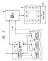
- Fig. 7 illustrates an example of an image information presentation system which utilizes the navigator creating and displaying apparatus of the present invention.
- This system successively offers a predetermined sequence of basic image information to users and selectively displays optional image information related to a displayed image in which they are interested.
- the fixed sequence of basic image information units are prestored, in correspondence with their identifiers, in an image presentation management section 42 in the image information management device 40, and optional image information units related to each of the basic image information units are prestored, in correspondence with their identifiers, in an optional image management section 41.
- an image presentation control device 90 Upon each readout of the basic image information units one by one from the image presentation management section 42, an image presentation control device 90 supplies the read-out image information unit to the display 60, wherein it is displayed in the center window W0. At the same time, the image presentation control device 90 provides the identifier of the displayed image information unit to the navigator generator 50 to request the generation of navigators. As in the case of Fig. 2, the navigator generator 50 reads out one or more identifiers of adjoining optional image information units for the received identifier from a table in the relation management device 30, the table being similar to Table II shown in Fig. 4B.
- the navigator generator 50 uses the read-out one or more identifiers to read out one or more corresponding optional image information units from the optional image management device 41 and assembles them into navigators, thereafter sending them to the image presentation control device 90.
- the image display control device 90 provides the navigators to the display 60, wherein they are displayed in predetermined ones of the small windows W1, W2 and W3. In this fashion, the sequence of basic image information units are displayed one by one at predetermined time intervals, together with the navigators to the optional image information units related with the basic image information unit being displayed.
- navigators may be displayed in predetermined small windows as mentioned above. It is also possible to provide a mode in which when a command of selecting the front or next page is issued by the user to the image presentation control device 90 via the input means of the display 60 during displaying one of the basic images as the core image, the immediately preceding or succeeding basic image in the sequence can be displayed as the core image.
- the image presentation control device 90 stops the sequential readout of the image presentation management device 42 and reads out therefrom the specified optional image information unit and sends the identifier of the selected navigator to the navigator generator 50, causing it to produce navigators to other optional image information units related with the selected optional image information unit.
- the selected optional image information unit is displayed as the core image
- the original basic image corresponding to the selected optional image information unit is displayed as one of the navigators, thereby enabling the user to easily switch the display of the selected optional image information unit to the display of the original basic image information unit corresponding thereto.
- Fig. 9 there is illustrated an embodiment of the navigator creating and display apparatus of the present invention as being applied to an image communication system in which the image database 100 and the display 60 are disposed at remote locations or at the same location.
- the transmitting side includes an input device 140 and an image communication control unit 150
- the receiving side includes an image communication control unit 170 and the display 60 provided with the input means 60A.
- at least one image database 100 forming the navigator creating and display apparatus of the present invention is provided.
- the transmitting side and the receiving side are interconnected by a channel Ch via a communication processing unit 160 acting as a relay station.
- the broken lines from the image database 100 to the image communication control unit 150 on the transmitting side, the communication processing unit 160 and the image communication control unit 170 on the receiving side indicate that the image database 100 can be provided in any one of the transmitting side, the relay station and the receiving side.
- the transmitting side and the receiving side may also be connected directly, omitting the communication processing unit 160.
- a desired one of the related image information units in the image database provided in the transmitting side is accessible from the receiving side based on the image information unit A and the navigators to the image information units related thereto being displayed on the display 60.
- the related image information unit specified as a core image in the receiving side and new navigators are produced by the image database 100 in the transmitting side and then are transferred to the receiving side.
- the latter requests the former to produce navigators to image information units related to the image information unit A sent from the transmitting side and transmits the navigators obtained from the image database 100 to the receiving side, together with the image information unit A. Also in this case, a desired one of the related image information units in the image database 100 provided in association with the communication processing unit 160 is accessible from the receiving side, based on the image information unit A and the navigators displayed on the display 60.
- the image database is provided in association with the image communication control unit 170 on the receiving side
- the image database provided on the receiving side can be accessed for a desired image information unit related to the image information unit A sent from the transmitting side.
- an identifier A may also be input from the input device 140 on the transmitting side in place of the image information unit. Also in such an instance, the identifier A is provided to the navigator generator 50 to produce navigators to related image information units, the image information unit corresponding to the identifier A is read out of the image information management device 40, and the read-out image information unit corresponding to the identifier A and the navigators created by the navigator generator 50 are displayed on the display screen of the display 60 on the receiving side. Accordingly, a desired related image information unit in the image database 100 is accessible from the receiving side.
- image information unit are related with one another for each property or attribute in the direction of their magnitudes in the property and navigators to all image information units, which adjoin a displayed main image in the above relating direction, are displayed together with the main image, so that the user can judge which of the navigators should be selected for displaying the corresponding image information unit next as the main image so as to reach the image information unit descired to get.
- image information units related with the main image are displayed as navigators, it is very likely that the user happens to come across information initially unexpected, but vary valuable for him.
Landscapes
- Engineering & Computer Science (AREA)
- Physics & Mathematics (AREA)
- Theoretical Computer Science (AREA)
- Mathematical Physics (AREA)
- Data Mining & Analysis (AREA)
- Databases & Information Systems (AREA)
- General Engineering & Computer Science (AREA)
- General Physics & Mathematics (AREA)
- Information Retrieval, Db Structures And Fs Structures Therefor (AREA)
- Processing Or Creating Images (AREA)
- Navigation (AREA)
Claims (25)
- Verfahren zum Erzeugen und Anzeigen von Hinweiszeichen auf verwandte Bildinformationseinheiten durch Benutzung von Bildinformationseinheiten, welche miteinander in einer Richtung ihrer Größen in Beziehung stehen, die für jede Eigenschaft jeder Abbildung definiert und in einer Bildinformationsspeicher- und -verwaltungseinrichtung gespeichert und verwaltet werden, mit den folgenden Schritten:- Anzeigen einer ersten Bildinformationseinheit als eine Hauptabbildung auf einem Sichtgerät;- Lesen aller zweiten Bildinformationseinheiten aus der Bildinformationsspeicher- und -verwaltungseinrichtung, wobei eine zweite Informationseinheit eine Bildinformationseinheit ist, die mit der ersten Bildinformationseinheit verwandt ist und an die erste Bildinformationseinheit in Richtung irgendeiner der genannten Größen angrenzt;- Verarbeiten der gelesenen zweiten Bildinformationseinheiten und Erzeugen der verarbeiteten Bildinformationseinheiten, welche die zweiten Bildinformationseinheiten darstellen, als die Hinweiszeichen; und- Anzeigen der Hinweiszeichen auf dem Sichtgerät zusammen mit der ersten Bildinformationseinheit als die genannte Hauptabbildung;- wodurch angezeigt wird, daß eine willkürliche der mit der angezeigten ersten Bildinformationseinheit verwandten zweiten Bildinformationseinheiten als die nächste Hauptabbildung gewählt werden kann.
- Verfahren nach Anspruch 1, bei dem die in der Bildinformationsspeicher- und -verwaltungseinrichtung gespeicherten und verwalteten Bildinformationseinheiten durch ein willkürliches Kriterium in eine Vielzahl von Gruppen unterteilt werden und die Bildinformationseinheiten in jeder der Gruppen miteinander für jede einer Vielzahl im voraus ausgewählter Eigenschaften von vorherbestimmter Priorität in der Reihenfolge ihrer für jede dieser Eigenschaften vorherbestimmten Größen in Beziehung stehen.
- Verfahren nach Anspruch 2, bei dem eine vorherbestimmte der Bildinformationseinheiten in jeder der in der Bildspeicher- und -verwaltungseinrichtung gespeicherten Gruppen als eine repräsentative Bildinformationseinheit jeder der Gruppen definiert wird, und der Schritt des Lesens der zweiten Bildinformationseinheiten aus der Bildinformationsspeicher- und -verwaltungseinrichtung ein Schritt ist, bei dem alle angrenzenden Bildinformationseinheiten, die mit der ersten Bildinformationseinheit durch jede der Eigenschaften in der gleichen Gruppe wie die erste Bildinformationseinheit verwandt sind, und die repräsentative Bildinformationseinheit mindestens einer der Gruppen, die sich von der Gruppe der ersten Bildinformationseinheit unterscheidet, als die zweiten Bildinformationseinheiten gelesen werden, welche mit der ersten Bildinformationseinheit verwandt sind.
- Verfahren nach Anspruch 1, 2 oder 3, bei dem der Schritt des Erzeugens der verarbeiteten Bildinformationseinheiten als die Hinweiszeichen einen Schritt des Zusammenziehens der aus der Bildinformationsspeicher- und -verwaltungseinrichtung gelesenen Bildinformationseinheiten einschließt.
- Verfahren nach Anspruch 1, 2 oder 3, bei dem der Schritt des Erzeugens der verarbeiteten Bildinformationseinheiten als die Hinweiszeichen ein Schritt ist, bei dem Information, welche die Art der Eigenschaft andeutet, in der die erste Bildinformationseinheit mit den zweiten Bildinformationseinheiten verwandt ist, zu Bildkörpern der Hinweiszeichen addiert wird, welche Bildinformationseinheiten sind, die durch Zusammenziehen der aus der Bildinformationsspeicher- und -verwaltungseinrichtung gelesenen zweiten Bildinformationseinheiten erhalten wurden.
- Verfahren nach Anspruch 1 oder 3, bei dem der Schritt des Erzeugens der verarbeiteten Bildinformationseinheiten als die Hinweiszeichen ein Schritt ist, bei dem Information, die die Gruppe der repräsentativen Bildinformationseinheit mindestens einer Gruppe anzeigt, die sich von der der ersten Bildinformationseinheit unterscheidet und damit verwandt ist, zu Bildkörpern der Hinweiszeichen addiert wird, die Bildinformationseinheiten sind, welche durch Zusammenziehen der aus der Bildinformationsspeicher- und -verwaltungseinrichtung gelesenen zweiten Bildinformationseinheiten erhalten wurden.
- Verfahren nach Anspruch 1, 2 oder 3, bei dem die Bildinformationsspeicher- und -verwaltungseinrichtung die Beziehungen zwischen Bildinformationseinheiten und deren Erkennungszeichen und die Beziehungen der Bildinformationseinheiten für jede Eigenschaft in Form von Beziehungen ihrer Erkennungszeichen speichert und verwaltet; die erste Bildinformationseinheit von einer anderen Quelle als der Bildinformationsspeicher- und -verwaltungseinrichtung bereitgestellt wird; und der Schritt des Lesens der zweiten Bildinformationseinheiten aus der Bildinformationsspeicher- und -verwaltungseinrichtung einen Schritt der Überprüfung der Beziehungen der Bildinformationseinheiten und ihrer Erkennungszeichen in der Bildinformationsspeicher- und -verwaltungseinrichtung und das Lesen eines ersten Erkennungszeichens entsprechend der ersten Bildinformationseinheit, einen Schritt des Überprüfens der Bildinformationsspeicher- und -verwaltungseinrichtung auf alle zweiten Erkennungszeichen, die unmittelbar mit dem ersten Erkennungszeichen verwandt sind, und das Lesen der zweiten Erkennungszeichen sowie einen Schritt des Lesens von Bildinformationseinheiten entsprechend den zweiten Erkennungszeichen als die zweiten Bildinformationseinheiten aus der Bildinformationsspeicher- und -verwaltungseinrichtung einschließt.
- Verfahren nach Anspruch 1, 2 oder 3, ferner mit einem Schritt der Auswahl eines der auf dem Sichtgerät angezeigten Hinweiszeichen; einem Schritt des Lesens einer Bildinformationseinheit entsprechend dem gewählten Hinweiszeichen als erneuerte erste Bildinformationseinheit aus der Bildinformationsspeicher- und -verwaltungseinrichtung, sowie einem Schritt des Anzeigens der erneuerten ersten Bildinformationseinheit als die erneuerte Hauptabbildung auf dem Sichtgerät.
- Verfahren nach Anspruch 1, 2 oder 3, bei dem die erste Bildinformationseinheit eine willkürliche einer Vielzahl von Bildinformationseinheiten ist, die aus der Bildinformationsspeicher- und -verwaltungseinrichtung in einer vorherbestimmten Folge gelesen werden.
- Verfahren nach Anspruch 1, 2 oder 3, bei dem die erste Bildinformationseinheit auf einer Sendeseite eines Bildinformationsübermittlungssystems generiert wird, und die Hinweiszeichen und die generierte erste Bildinformationseinheit auf dem Sichtgerät angezeigt werden, welches auf einer Empfangsseite des Bildinformationsübermittlungssystems vorgesehen ist.
- Hinweiszeichenerzeugungs- und Anzeigevorrichtung mit:- einer Bildinformationsspeicher- und -verwaltungseinrichtung (110) zum Speichern und Verwalten von Bildinformationseinheiten, die in einer Richtung ihrer Größen, die für jede Eigenschaft jeder Abbildung definiert sind, miteinander verwandt sind;- einem Sichtgerät (60) zum Anzeigen einer ersten Bildinformationseinheit als Hauptabbildung; und- einem Hinweisgenerator (50) zum Lesen aller zweiten Bildinformationseinheiten aus der Bildinformationsspeicher- und -verwaltungseinrichtung, wobei eine zweite Informationseinheit eine Bildinformationseinheit ist, die mit der ersten Bildinformationseinheit verwandt ist und an die erste Bildinformationseinheit in der Richtung irgendeiner der Größen angrenzt, und zum Verarbeiten der gelesenen zweiten Bildinformationseinheiten zur Erzeugung von Hinweiszeichen, welche die zweiten Bildinformationseinheiten bezeichnen, und Zuführen dieser Hinweiszeichen zu dem Sichtgerät;- worin das Sichtgerät (60) die Hinweiszeichen zusammen mit der Hauptabbildung darstellt.
- Vorrichtung nach Anspruch 11, bei der die Bildinformationsspeicher- und -verwaltungseinrichtung (110) eine Bildinformationsverwaltungsvorrichtung (40) zum Speichern und Verwalten der Beziehungen von Bildinformationseinheiten und deren Erkennungszeichen und eine Verwandtschaftsverwaltungsvorrichtung (30) zum Speichern und Verwalten der Beziehungen der Bildinformationseinheiten für jede Eigenschaft in Form der Beziehungen ihrer Erkennungszeichen einschließt.
- Vorrichtung nach Anspruch 11, bei der der Hinweiszeichengenerator (50) eine Bildkontrahiereinrichtung (52A) einschließt, wodurch die aus der Bildinformationsspeicher- und -verwaltungseinrichtung gelesenen zweiten Bildinformationseinheiten zu Bildkörpern der Hinweiszeichen zusammengezogen werden.
- Vorrichtung nach Anspruch 12, bei der der Hinweiszeichengenerator (50) ferner eine Bildwiedergewinnungssteuereinrichtung (53) aufweist, welche auf die Wahl eines der auf dem Sichtgerät (60) angezeigten Hinweiszeichen anspricht und ein erstes Erkennungszeichen einer Bildinformationseinheit entsprechend dem gewählten Hinweiszeichen an den Hinweiszeichengenerator (50) liefert und die entsprechende Bildinformationseinheit als erneuerte erste Bildinformationseinheit durch die Benutzung des ersten Erkennungszeichens liest, und worin der Hinweiszeichengenerator (50) eine Einrichtung (52) einschließt, die aus der Verwandtschaftsverwaltungsvorrichtung (30) alle zweiten Erkennungszeichen liest, die in den Richtungen angrenzen und mit dem von der Bildwiedergewinnungssteuereinrichtung (53) gelieferten ersten Erkennungszeichen verwandt sind, aus der Bildinformationsverwaltungsvorrichtung (40) durch die Benutzung der gelesenen zweiten Erkennungszeichen Bildinformationseinheiten, welche den zweiten Erkennungszeichen entsprechen, als neue zweite Bildinformationseinheiten liest, und die neuen zweiten Bildinformationseinheiten verarbeitet, um neue Hinweiszeichen zu schaffen, wobei die Bildwiedergewinnungssteuereinrichtung (53) die erneuerte erste Bildinformationseinheit und die neuen Hinweiszeichen an das Sichtgerät (60) zur Anzeige auf demselben liefert.
- Vorrichtung nach Anspruch 12, bei der die Bildinformationsverwaltungsvorrichtung (40) einen Bilddarstellungsverwaltungsabschnitt (42) zum Speichern und Verwalten einer Folge grundlegender Bildinformationseinheiten, denen jeweils Erkennungszeichen zugeordnet sind, sowie einen wahlweisen Bildinformationsverwaltungsabschnitt (41) zum Speichern und Verwalten der Erkennungszeichen der grundlegenden Bildinformationseinheiten und der Bildinformationseinheiten als wahlweise Bildinformationseinheiten einschließt, worin die Verwandtschaftsverwaltungsvorrichtung (30) die Verwandtschaften der wahlweisen Bildinformationseinheiten mit den grundlegenden Bildinformationseinheiten speichert und verwaltet als die Beziehungen zwischen den Erkennungszeichen der grundlegenden Bildinformationseinheiten und Erkennungszeichen der wahlweisen Bildinformationseinheiten, die Folge grundlegender Bildinformationseinheiten der Reihe nach aus dem Bilddarstellungsverwaltungsabschnitt (42) liest und sie eine nach der anderen als die Hauptabbildung auf dem Sichtgerät (60) darstellt, das Erkennungszeichen jeder der grundlegenden Bildinformationseinheiten an den Hinweiszeichengenerator (50) liefert, um ihn anzuweisen, mindestens ein Hinweiszeichen zu erzeugen, welches mit jeder grundlegenden Bildinformationseinheit verwandt ist, und mindestens ein Hinweiszeichen an das Sichtgerät zur Anzeige auf demselben liefert.
- Vorrichtung nach Anspruch 12, bei dem der Hinweiszeichengenerator (50) und die Bildinformationsspeicher- und -verwaltungseinrichtung (110) auf einer Sendeseite in einem Informationsübermittlungssystem vorgesehen sind, in welchem die Sendeseite sowie eine Empfangsseite miteinander über einen Kommunikationskanal verbunden sind und das Sichtgerät (60) auf der Empfangsseite vorgesehen ist.
- Vorrichtung nach Anspruch 12, bei dem der Hinweiszeichengenerator (50) und die Bildinformationsspeicher- und -verwaltungseinrichtung (110) mit einer weitermeldenden Kommunikationsverarbeitungseinheit (160) in einem Informationsübermittlungssystem verbunden sind, in welchem Sende- und Empfangsseite durch die Kommunikationsverarbeitungseinheit (160) über einen Kommunikationskanal miteinander verbunden sind und das Sichtgerät (60) auf der Empfangsseite vorgesehen ist.
- Vorrichtung nach Anspruch 12, bei der der Hinweiszeichengenerator (50), die Bildinformationsspeicher- und -verwaltungseinrichtung (110) und das Sichtgerät (60) auf einer Empfangsseite in einem Informationsübermittlungssystem vorgesehen sind, in welchem eine Sendeseite und die Empfangsseite über einen Kommunikationskanal miteinander verbunden sind.
- Vorrichtung nach Anspruch 16, bei dem die Sendeseite eine Eingabeeinrichtung (140) zum Eingeben eines Erkennungszeichens einer zu übermittelnden Bildinformationseinheit sowie Bildübermittlungssteuereinrichtungen (150) einschließt, welche eine Bildinformationseinheit entsprechend dem Erkennungszeichen als die erste Bildinformationseinheit aus der Bildinformationsverwaltungsvorrichtung (40) lesen und die gelesene Bildinformationseinheit an die Empfangsseite zusammen mit vom Hinweiszeichengenerator (50) empfangenen Hinweiszeichen sendet, und worin der Hinweiszeichengenerator (50) alle Erkennungszeichen liest, die angrenzend verwandt sind mit dem eingegebenen Erkennungszeichen von der Verwandtschaftsverwaltungsvorrichtung, Bildinformationseinheiten entsprechend den gelesenen Erkennungszeichen als die zweiten Bildinformationseinheiten aus der Bildinformationsverwaltungsvorrichtung (40) liest und die Hinweiszeichen erzeugt.
- Vorrichtung nach Anspruch 16, bei der die Sendeseite eine Eingabeeinrichtung (140) zum Eingeben einer zu übertragenden Bildinformationseinheit sowie eine Bildübermittlungssteuereinrichtung (150) einschließt, welche die eingegebene Bildinformationseinheit als erste Bildinformationseinheit an den Hinweiszeichengenerator (50) liefert und die vom Hinweiszeichengenerator empfangenen Hinweiszeichen sowie die erste Bildinformationseinheit an die Empfangsseite sendet, und worin der Hinweiszeichengenerator die Hinweiszeichen entsprechend allen zweiten Bildinformationseinheiten erzeugt, die angrenzend verwandt sind mit der ersten Bildinformationseinheit, welche von der Bildübermittlungssteuereinrichtung empfangen wurde, und die Hinweiszeichen an die Bildübermittlungssteuereinrichtung liefert.
- Vorrichtung nach Anspruch 17, worin die weitermeldende Kommunikationsverarbeitungseinheit (160) eine von der Sendeseite übermittelte Bildinformationseinheit als die erste Bildinformationseinheit an den Hinweiszeichengenerator (50) liefert und die vom Hinweiszeichengenerator empfangenen Hinweiszeichen sowie die erste Bildinformationseinheit an die Empfangsseite sendet, und worin der Hinweiszeichengenerator die Hinweiszeichen entsprechend allen zweiten Bildinformationseinheiten erzeugt, die angrenzend verwandt sind mit der ersten Bildinformationseinheit, welche von der weitermeldenden Kommunikationsverarbeitungseinheit (160) empfangen wurde, und die Hinweiszeichen an die weitermeldende Kommunikationsverarbeitungseinheit (160) liefert.
- Vorrichtung nach Anspruch 17, bei dem die weitermeldende Kommunikationsverarbeitungseinheit (160) ein von der Sendeseite an den Hinweiszeichengenerator (50) gesandtes Erkennungszeichen liefert, eine Bildinformationseinheit entsprechend dem empfangenen Erkennungszeichen als die erste Bildinformationseinheit aus der Bildinformationsverwaltungsvorrichtung (40) liest, und die gelesene Bildinformationseinheit sowie die vom Hinweiszeichengenerator (50) empfangenen Hinweiszeichen an die Empfangsseite sendet, und worin der Hinweiszeichengenerator alle Erkennungszeichen liest, die angrenzend verwandt sind mit dem empfangenen Erkennungszeichen von der Verwandtschaftsverwaltungsvorrichtung (30), Bildinformationseinheiten entsprechend allen gelesenen Erkennungszeichen als die zweiten Bildinformationseinheiten aus der Bildinformationsverwaltungsvorrichtung liest, und die Hinweiszeichen erzeugt.
- Vorrichtung nach Anspruch 18, bei der die Empfangsseite eine Bildübermittlungssteuereinrichtung (170) einschließt, welche eine empfangene Bildinformationseinheit als die erste Bildinformationseinheit an den Hinweiszeichengenerator (50) liefert und die vom Hinweiszeichengenerator empfangenen Hinweiszeichen sowie die erste Bildinformationseinheit an das Sichtgerät (60) liefert, und worin der Hinweiszeichengenerator die Hinweiszeichen entsprechend allen zweiten Bildinformationseinheiten erzeugt, die angrenzend verwandt sind mit der ersten, von der Bildübermittlungssteuereinrichtung (170) empfangenen Bildinformationseinheit, und die Hinweiszeichen an die Bildübermittlungssteuereinrichtung (170) liefert.
- Vorrichtung nach Anspruch 18, bei der die Empfangsseite eine Bildübermittlungssteuereinrichtung (170) einschließt, die ein empfangenes Erkennungszeichen an den Hinweiszeichengenerator (50) liefert, eine Bildinformationseinheit entsprechend dem empfangenen Erkennungszeichen als die erste Bildinformationseinheit aus der Bildinformationsverwaltungsvorrichtung (40) liest und die gelesene Bildinformationseinheit sowie die vom Hinweiszeichengenerator empfangenen Hinweiszeichen an das Sichtgerät (60) liefert, und worin der Hinweiszeichengenerator aus der Verwandtschaftsverwaltungsvorrichtung (30) alle Erkennungszeichen liest, die angrenzend verwandt sind mit dem von der Bildübermittlungssteuereinrichtung (170) empfangenen Erkennungszeichen, Bildinformationseinheiten entsprechend den gelesenen Erkennungszeichen als die zweiten Bildinformationseinheiten aus der Bildinformationsverwaltungsvorrichtung (40) liest und die Hinweiszeichen erzeugt.
- Vorrichtung nach Anspruch 11, 12 oder 13, worin die Bildinformationsspeicher- und -verwaltungseinrichtung (40) Aufzeichnungsinformationseingabeeinrichtungen (70) zur Eingabe einer aufzuzeichnenden Bildinformationseinheit einschließt, Eigenschaftsverwaltungseinrichtungen (10) zum Verwalten der Arten von Abbildungen und der Arten von dafür zu extrahierenden Eigenschaften, sowie Merkmalsableiteinrichtungen (20), wodurch anhand der Art einer in der aufzuzeichnenden Bildinformationseinheit enthaltenen Abbildung, die von den Aufzeichnungsinformationseingabeeinrichtungen (70) eingegeben wurde, eine Vielzahl von Arten entsprechender, abzuleitender Eigenschaften aus den Eigenschaftsverwaltungseinrichtungen (10) gelesen wird und anhand der Art der Abbildung und der Arten der Eigenschaften bestimmt wird, mit welcher der Bildinformationseinheiten, die durch die Eigenschaften in der Bildinformationsspeicher- und -verwaltungseinrichtung (110) verwandt sind, die aufzuzeichnende Bildinformationseinheit in Beziehung gesetzt werden sollte.
Applications Claiming Priority (2)
| Application Number | Priority Date | Filing Date | Title |
|---|---|---|---|
| JP158904/88 | 1988-06-27 | ||
| JP15890488 | 1988-06-27 |
Publications (3)
| Publication Number | Publication Date |
|---|---|
| EP0348884A2 EP0348884A2 (de) | 1990-01-03 |
| EP0348884A3 EP0348884A3 (de) | 1991-09-04 |
| EP0348884B1 true EP0348884B1 (de) | 1995-12-13 |
Family
ID=15681899
Family Applications (1)
| Application Number | Title | Priority Date | Filing Date |
|---|---|---|---|
| EP89111663A Expired - Lifetime EP0348884B1 (de) | 1988-06-27 | 1989-06-27 | Verfahren und Vorrichtung zur Erzeugung und Anzeige von Hinweiszeichen zur Hinführung zu verwandten Bildinformationen |
Country Status (5)
| Country | Link |
|---|---|
| US (1) | US5123088A (de) |
| EP (1) | EP0348884B1 (de) |
| JP (1) | JP2759121B2 (de) |
| CA (1) | CA1315410C (de) |
| DE (1) | DE68925073T2 (de) |
Families Citing this family (65)
| Publication number | Priority date | Publication date | Assignee | Title |
|---|---|---|---|---|
| US6978277B2 (en) * | 1989-10-26 | 2005-12-20 | Encyclopaedia Britannica, Inc. | Multimedia search system |
| US5761655A (en) * | 1990-06-06 | 1998-06-02 | Alphatronix, Inc. | Image file storage and retrieval system |
| JPH04156685A (ja) * | 1990-10-19 | 1992-05-29 | Sanyo Electric Co Ltd | 画像選択装置 |
| US5546572A (en) * | 1991-08-28 | 1996-08-13 | Hitachi, Ltd. | Method for retrieving database of image information |
| JPH05108603A (ja) * | 1991-10-18 | 1993-04-30 | Toshiba Corp | シミユレーシヨンシステム |
| JP3050348B2 (ja) * | 1992-04-17 | 2000-06-12 | インターナショナル・ビジネス・マシーンズ・コーポレイション | プロセス制御システムにおけるユーザ制御のための方法と装置 |
| JPH05334357A (ja) * | 1992-06-04 | 1993-12-17 | Matsushita Graphic Commun Syst Inc | 電子ファイル装置のページめくり装置 |
| JPH0652224A (ja) * | 1992-07-29 | 1994-02-25 | Fujitsu Ltd | カード型データベース検索装置 |
| US5630121A (en) * | 1993-02-02 | 1997-05-13 | International Business Machines Corporation | Archiving and retrieving multimedia objects using structured indexes |
| US5897652A (en) * | 1993-04-23 | 1999-04-27 | Sony Corporation | Memory control device and address generating circuit |
| JP3353382B2 (ja) * | 1993-04-23 | 2002-12-03 | ソニー株式会社 | 記録又は再生装置、及びメモリ制御装置 |
| JP3353381B2 (ja) * | 1993-04-23 | 2002-12-03 | ソニー株式会社 | 記録再生装置 |
| US6108001A (en) * | 1993-05-21 | 2000-08-22 | International Business Machines Corporation | Dynamic control of visual and/or audio presentation |
| US5647058A (en) * | 1993-05-24 | 1997-07-08 | International Business Machines Corporation | Method for high-dimensionality indexing in a multi-media database |
| JP3438262B2 (ja) * | 1993-07-19 | 2003-08-18 | ソニー株式会社 | 情報処理方法 |
| US6169995B1 (en) | 1994-03-17 | 2001-01-02 | Hitachi, Ltd. | Link information maintenance management method |
| JP4044971B2 (ja) * | 1994-03-17 | 2008-02-06 | 株式会社日立製作所 | イメージ情報を用いた検索方法 |
| FR2719136B1 (fr) * | 1994-04-25 | 1996-06-21 | Saint Laurent De Jean | Procédé et dispositif de saisie de données assistée par ordinateur. |
| US5854923A (en) * | 1994-06-21 | 1998-12-29 | International Business Machines Corp. | Facility for the intelligent selection of information objects (persona) |
| KR0127763B1 (ko) * | 1994-06-29 | 1998-04-02 | 김광호 | 교육용 비디오시스템 |
| US5544354A (en) * | 1994-07-18 | 1996-08-06 | Ikonic Interactive, Inc. | Multimedia matrix architecture user interface |
| US6604103B1 (en) | 1994-09-02 | 2003-08-05 | Mark A. Wolfe | System and method for information retrieval employing a preloading procedure |
| US7103594B1 (en) | 1994-09-02 | 2006-09-05 | Wolfe Mark A | System and method for information retrieval employing a preloading procedure |
| US5715445A (en) * | 1994-09-02 | 1998-02-03 | Wolfe; Mark A. | Document retrieval system employing a preloading procedure |
| US7467137B1 (en) | 1994-09-02 | 2008-12-16 | Wolfe Mark A | System and method for information retrieval employing a preloading procedure |
| US5592600A (en) * | 1994-09-27 | 1997-01-07 | International Business Machines Corporation | Animated display showing execution of object-oriented programs |
| WO1996017313A1 (en) * | 1994-11-18 | 1996-06-06 | Oracle Corporation | Method and apparatus for indexing multimedia information streams |
| US5717468A (en) * | 1994-12-02 | 1998-02-10 | International Business Machines Corporation | System and method for dynamically recording and displaying comments for a video movie |
| US7336279B1 (en) | 1994-12-16 | 2008-02-26 | Canon Kabushiki Kaisha | Intuitive hierarchical time-series data display method and system |
| WO1996024216A1 (en) | 1995-01-31 | 1996-08-08 | Transcenic, Inc. | Spatial referenced photography |
| JP3599405B2 (ja) * | 1995-03-03 | 2004-12-08 | キヤノン株式会社 | データ表示方法及びそのシステム |
| US5627980A (en) * | 1995-03-20 | 1997-05-06 | Xerox Corporation | Elision based presentation of ordered data |
| US7302638B1 (en) | 1995-06-07 | 2007-11-27 | Wolfe Mark A | Efficiently displaying and researching information about the interrelationships between documents |
| AUPN360195A0 (en) | 1995-06-16 | 1995-07-13 | Canon Information Systems Research Australia Pty Ltd | Colour selection tool |
| US6012055A (en) * | 1996-04-09 | 2000-01-04 | Silicon Graphics, Inc. | Mechanism for integrated information search and retrieval from diverse sources using multiple navigation methods |
| MY120211A (en) * | 1996-05-01 | 2005-09-30 | Casio Computer Co Ltd | Document output device |
| US5832495A (en) | 1996-07-08 | 1998-11-03 | Survivors Of The Shoah Visual History Foundation | Method and apparatus for cataloguing multimedia data |
| US6006252A (en) | 1996-10-08 | 1999-12-21 | Wolfe; Mark A. | System and method for communicating information relating to a network resource |
| US6622148B1 (en) | 1996-10-23 | 2003-09-16 | Viacom International Inc. | Interactive video title selection system and method |
| JP3627427B2 (ja) * | 1997-02-03 | 2005-03-09 | 富士ゼロックス株式会社 | データ出力システム |
| US5825362A (en) * | 1997-05-07 | 1998-10-20 | Datahand Corporation | Graphical user interface with keyboard display graphical |
| US8626763B1 (en) | 1997-05-22 | 2014-01-07 | Google Inc. | Server-side suggestion of preload operations |
| US5973734A (en) | 1997-07-09 | 1999-10-26 | Flashpoint Technology, Inc. | Method and apparatus for correcting aspect ratio in a camera graphical user interface |
| JP4540134B2 (ja) * | 1997-11-05 | 2010-09-08 | 株式会社ニコン | 情報処理装置および方法、並びに記録媒体 |
| US6292813B1 (en) | 1997-11-17 | 2001-09-18 | Mark A. Wolfe | System and method for communicating information relating to a network resource |
| US7257604B1 (en) | 1997-11-17 | 2007-08-14 | Wolfe Mark A | System and method for communicating information relating to a network resource |
| US6452909B1 (en) | 1998-07-24 | 2002-09-17 | Texas Instruments Israel Ltd. | Time division duplex transceiver utilizing a single oscillator |
| JP2000105772A (ja) * | 1998-07-28 | 2000-04-11 | Sharp Corp | 情報管理装置 |
| JP2000076267A (ja) * | 1998-08-31 | 2000-03-14 | Sharp Corp | 情報検索方法、情報検索装置、及び情報検索プログラムを記録したコンピュータ読み取り可能な記録媒体 |
| US6549911B2 (en) | 1998-11-02 | 2003-04-15 | Survivors Of The Shoah Visual History Foundation | Method and apparatus for cataloguing multimedia data |
| US6317141B1 (en) | 1998-12-31 | 2001-11-13 | Flashpoint Technology, Inc. | Method and apparatus for editing heterogeneous media objects in a digital imaging device |
| US6486898B1 (en) * | 1999-03-31 | 2002-11-26 | Koninklijke Philips Electronics N.V. | Device and method for a lattice display |
| JP2001160057A (ja) * | 1999-12-03 | 2001-06-12 | Nippon Telegr & Teleph Corp <Ntt> | 画像の階層的分類方法、および画像の分類・検索装置、およびこの方法を実行するプログラムを記録した記録媒体 |
| US6804295B1 (en) * | 2000-01-07 | 2004-10-12 | International Business Machines Corporation | Conversion of video and audio to a streaming slide show |
| US6574638B1 (en) | 2000-09-12 | 2003-06-03 | Survivors Of The Shoah Visual History Foundation | Method and apparatus for cataloguing multimedia data using surveying data |
| US6581071B1 (en) | 2000-09-12 | 2003-06-17 | Survivors Of The Shoah Visual History Foundation | Surveying system and method |
| JP3878518B2 (ja) * | 2002-07-08 | 2007-02-07 | 松下電器産業株式会社 | データ検索装置 |
| JP4080815B2 (ja) * | 2002-08-13 | 2008-04-23 | 富士通株式会社 | サービス情報提供方法 |
| JP2005174212A (ja) * | 2003-12-15 | 2005-06-30 | Sony Corp | 情報処理装置、および情報処理方法、並びにコンピュータ・プログラム |
| FI20055369A0 (fi) * | 2005-06-30 | 2005-06-30 | Nokia Corp | Menetelmä ja laite digitaalisten mediatiedostojen käsittelemiseksi |
| JP4536637B2 (ja) * | 2005-10-28 | 2010-09-01 | 株式会社スクウェア・エニックス | 情報散策装置及び方法、プログラム並びに記録媒体 |
| JP4885602B2 (ja) * | 2006-04-25 | 2012-02-29 | 富士フイルム株式会社 | 画像再生装置ならびにその制御方法およびその制御プログラム |
| US9224145B1 (en) | 2006-08-30 | 2015-12-29 | Qurio Holdings, Inc. | Venue based digital rights using capture device with digital watermarking capability |
| JP5217139B2 (ja) * | 2006-09-29 | 2013-06-19 | カシオ計算機株式会社 | 画像検索装置、画像検索プログラム |
| US20100287502A1 (en) * | 2009-05-11 | 2010-11-11 | Olympus Imaging Corp. | Image search device and image search method |
Family Cites Families (3)
| Publication number | Priority date | Publication date | Assignee | Title |
|---|---|---|---|---|
| US4479196A (en) * | 1982-11-15 | 1984-10-23 | At&T Bell Laboratories | Hyperedge entity-relationship data base systems |
| JPS63254513A (ja) * | 1987-04-13 | 1988-10-21 | Toshiba Corp | 画面表示方法 |
| US4905163A (en) * | 1988-10-03 | 1990-02-27 | Minnesota Mining & Manufacturing Company | Intelligent optical navigator dynamic information presentation and navigation system |
-
1989
- 1989-06-26 US US07/370,968 patent/US5123088A/en not_active Expired - Fee Related
- 1989-06-26 JP JP1164246A patent/JP2759121B2/ja not_active Expired - Fee Related
- 1989-06-27 EP EP89111663A patent/EP0348884B1/de not_active Expired - Lifetime
- 1989-06-27 CA CA000603992A patent/CA1315410C/en not_active Expired - Fee Related
- 1989-06-27 DE DE68925073T patent/DE68925073T2/de not_active Expired - Fee Related
Also Published As
| Publication number | Publication date |
|---|---|
| JP2759121B2 (ja) | 1998-05-28 |
| US5123088A (en) | 1992-06-16 |
| CA1315410C (en) | 1993-03-30 |
| JPH02168354A (ja) | 1990-06-28 |
| DE68925073D1 (de) | 1996-01-25 |
| EP0348884A2 (de) | 1990-01-03 |
| EP0348884A3 (de) | 1991-09-04 |
| DE68925073T2 (de) | 1996-06-20 |
Similar Documents
| Publication | Publication Date | Title |
|---|---|---|
| US5123088A (en) | Method and apparatus for creating and displaying navigators for guiding to related image information | |
| US6768997B2 (en) | System and method for creating a search query using movable elements in a graphical user interface | |
| US7076502B2 (en) | Method, article of manufacture, and apparatus for generating a multi-dimensional record management index | |
| US5339247A (en) | Distributed data CAD system | |
| US6108657A (en) | Method, article of manufacture, and apparatus for generating a multi-dimensional record layout mapping | |
| US5933143A (en) | Method and apparatus for displaying a tree structure diagram representing a relationship among windows with icons representing respective windows | |
| US5937408A (en) | Method, article of manufacture, and apparatus for generating a multi-dimensional record structure foundation | |
| US5864856A (en) | Process and apparatus for simplifying access to information stored in databases | |
| JP4153883B2 (ja) | 階層型データベース装置および階層型データベース装置における製品選定方法およびプログラム | |
| US20060242564A1 (en) | Method and apparatus for indexing, searching and displaying data | |
| JP2000067083A (ja) | 地図情報提供システム及び地図情報検索方法 | |
| US5970493A (en) | Method, article of manufacture, and apparatus for generating a multi-dimensional record display | |
| US20080276217A1 (en) | Program and method for displaying relationships between objects | |
| US20010025287A1 (en) | Document integrated management apparatus and method | |
| US20010027463A1 (en) | Task priority decision apparatus and method, workflow system, work processing method, and recording medium | |
| US7268791B1 (en) | Systems and methods for visualization of data sets containing interrelated objects | |
| US7065748B2 (en) | Test specification formation supporting apparatus, method, and program, and recording medium | |
| JPH07295994A (ja) | 情報検索装置 | |
| JPH08272818A (ja) | 情報検索システム | |
| JPH08335223A (ja) | 画像検索システム | |
| KR101153534B1 (ko) | 웹 데이터 및 로컬 데이터에 대한 데이터 자동 태깅 방법및 데이터 자동 태깅 시스템 | |
| JP2833596B2 (ja) | 設備管理システム及び設備管理方法 | |
| JPH0340173A (ja) | 情報検索方法およびその装置 | |
| EP0864989A2 (de) | Verfahren und Gerät, um Dateien zu suchen und die gefundenen Dateien zu benutzen | |
| JP2506987B2 (ja) | 画像検索装置及び方法 |
Legal Events
| Date | Code | Title | Description |
|---|---|---|---|
| PUAI | Public reference made under article 153(3) epc to a published international application that has entered the european phase |
Free format text: ORIGINAL CODE: 0009012 |
|
| 17P | Request for examination filed |
Effective date: 19890627 |
|
| AK | Designated contracting states |
Kind code of ref document: A2 Designated state(s): DE FR GB |
|
| PUAL | Search report despatched |
Free format text: ORIGINAL CODE: 0009013 |
|
| RHK1 | Main classification (correction) |
Ipc: G06F 15/40 |
|
| AK | Designated contracting states |
Kind code of ref document: A3 Designated state(s): DE FR GB |
|
| 17Q | First examination report despatched |
Effective date: 19931216 |
|
| GRAA | (expected) grant |
Free format text: ORIGINAL CODE: 0009210 |
|
| AK | Designated contracting states |
Kind code of ref document: B1 Designated state(s): DE FR GB |
|
| REF | Corresponds to: |
Ref document number: 68925073 Country of ref document: DE Date of ref document: 19960125 |
|
| ET | Fr: translation filed | ||
| REG | Reference to a national code |
Ref country code: FR Ref legal event code: CA |
|
| PLBE | No opposition filed within time limit |
Free format text: ORIGINAL CODE: 0009261 |
|
| STAA | Information on the status of an ep patent application or granted ep patent |
Free format text: STATUS: NO OPPOSITION FILED WITHIN TIME LIMIT |
|
| 26N | No opposition filed | ||
| PGFP | Annual fee paid to national office [announced via postgrant information from national office to epo] |
Ref country code: FR Payment date: 19990531 Year of fee payment: 11 |
|
| PGFP | Annual fee paid to national office [announced via postgrant information from national office to epo] |
Ref country code: GB Payment date: 19990623 Year of fee payment: 11 |
|
| PGFP | Annual fee paid to national office [announced via postgrant information from national office to epo] |
Ref country code: DE Payment date: 19990628 Year of fee payment: 11 |
|
| PG25 | Lapsed in a contracting state [announced via postgrant information from national office to epo] |
Ref country code: GB Free format text: LAPSE BECAUSE OF NON-PAYMENT OF DUE FEES Effective date: 20000627 |
|
| GBPC | Gb: european patent ceased through non-payment of renewal fee |
Effective date: 20000627 |
|
| PG25 | Lapsed in a contracting state [announced via postgrant information from national office to epo] |
Ref country code: FR Free format text: LAPSE BECAUSE OF NON-PAYMENT OF DUE FEES Effective date: 20010228 |
|
| REG | Reference to a national code |
Ref country code: FR Ref legal event code: ST |
|
| PG25 | Lapsed in a contracting state [announced via postgrant information from national office to epo] |
Ref country code: DE Free format text: LAPSE BECAUSE OF NON-PAYMENT OF DUE FEES Effective date: 20010403 |