EP0349687A2 - Méthode et appareil pour encoder les adresses des secteurs d'un disque magnétique - Google Patents
Méthode et appareil pour encoder les adresses des secteurs d'un disque magnétique Download PDFInfo
- Publication number
- EP0349687A2 EP0349687A2 EP88306180A EP88306180A EP0349687A2 EP 0349687 A2 EP0349687 A2 EP 0349687A2 EP 88306180 A EP88306180 A EP 88306180A EP 88306180 A EP88306180 A EP 88306180A EP 0349687 A2 EP0349687 A2 EP 0349687A2
- Authority
- EP
- European Patent Office
- Prior art keywords
- sector
- code word
- symbols
- address code
- address
- Prior art date
- Legal status (The legal status is an assumption and is not a legal conclusion. Google has not performed a legal analysis and makes no representation as to the accuracy of the status listed.)
- Granted
Links
- 238000000034 method Methods 0.000 title claims abstract description 25
- 241000269627 Amphiuma means Species 0.000 claims 3
- 230000001360 synchronised effect Effects 0.000 description 2
- 230000010485 coping Effects 0.000 description 1
- 230000007547 defect Effects 0.000 description 1
- 230000000694 effects Effects 0.000 description 1
- 230000002093 peripheral effect Effects 0.000 description 1
- 230000000135 prohibitive effect Effects 0.000 description 1
- 238000010561 standard procedure Methods 0.000 description 1
Images


Classifications
-
- G—PHYSICS
- G11—INFORMATION STORAGE
- G11B—INFORMATION STORAGE BASED ON RELATIVE MOVEMENT BETWEEN RECORD CARRIER AND TRANSDUCER
- G11B27/00—Editing; Indexing; Addressing; Timing or synchronising; Monitoring; Measuring tape travel
- G11B27/10—Indexing; Addressing; Timing or synchronising; Measuring tape travel
- G11B27/102—Programmed access in sequence to addressed parts of tracks of operating record carriers
- G11B27/105—Programmed access in sequence to addressed parts of tracks of operating record carriers of operating discs
-
- G—PHYSICS
- G11—INFORMATION STORAGE
- G11B—INFORMATION STORAGE BASED ON RELATIVE MOVEMENT BETWEEN RECORD CARRIER AND TRANSDUCER
- G11B20/00—Signal processing not specific to the method of recording or reproducing; Circuits therefor
- G11B20/10—Digital recording or reproducing
- G11B20/18—Error detection or correction; Testing, e.g. of drop-outs
- G11B20/1833—Error detection or correction; Testing, e.g. of drop-outs by adding special lists or symbols to the coded information
-
- G—PHYSICS
- G11—INFORMATION STORAGE
- G11B—INFORMATION STORAGE BASED ON RELATIVE MOVEMENT BETWEEN RECORD CARRIER AND TRANSDUCER
- G11B27/00—Editing; Indexing; Addressing; Timing or synchronising; Monitoring; Measuring tape travel
- G11B27/10—Indexing; Addressing; Timing or synchronising; Measuring tape travel
- G11B27/19—Indexing; Addressing; Timing or synchronising; Measuring tape travel by using information detectable on the record carrier
- G11B27/28—Indexing; Addressing; Timing or synchronising; Measuring tape travel by using information detectable on the record carrier by using information signals recorded by the same method as the main recording
- G11B27/30—Indexing; Addressing; Timing or synchronising; Measuring tape travel by using information detectable on the record carrier by using information signals recorded by the same method as the main recording on the same track as the main recording
- G11B27/3027—Indexing; Addressing; Timing or synchronising; Measuring tape travel by using information detectable on the record carrier by using information signals recorded by the same method as the main recording on the same track as the main recording used signal is digitally coded
-
- H—ELECTRICITY
- H03—ELECTRONIC CIRCUITRY
- H03M—CODING; DECODING; CODE CONVERSION IN GENERAL
- H03M13/00—Coding, decoding or code conversion, for error detection or error correction; Coding theory basic assumptions; Coding bounds; Error probability evaluation methods; Channel models; Simulation or testing of codes
- H03M13/03—Error detection or forward error correction by redundancy in data representation, i.e. code words containing more digits than the source words
- H03M13/05—Error detection or forward error correction by redundancy in data representation, i.e. code words containing more digits than the source words using block codes, i.e. a predetermined number of check bits joined to a predetermined number of information bits
- H03M13/13—Linear codes
- H03M13/15—Cyclic codes, i.e. cyclic shifts of codewords produce other codewords, e.g. codes defined by a generator polynomial, Bose-Chaudhuri-Hocquenghem [BCH] codes
-
- G—PHYSICS
- G11—INFORMATION STORAGE
- G11B—INFORMATION STORAGE BASED ON RELATIVE MOVEMENT BETWEEN RECORD CARRIER AND TRANSDUCER
- G11B20/00—Signal processing not specific to the method of recording or reproducing; Circuits therefor
- G11B20/10—Digital recording or reproducing
- G11B2020/10916—Seeking data on the record carrier for preparing an access to a specific address
Definitions
- This invention relates to computer systems in general and more particularly to methods for locating stored data on a magnetic disk.
- Computer systems often use peripheral storage devices, such as magnetic disks, to store data.
- the data is stored on the disks in circular tracks.
- Each track is divided into a number of sectors usually consisting of either 512 or 576 bytes, that is, eight-bit symbols.
- Each sector in turn, consists of two sections, an address section and a data section.
- the sector is uniquely identified by address symbols which are stored in the address section of the sector when the disk is formatted.
- the disk drive has a read/write head which must be over a sector to perform a storage of retrieval ("write” or "read") operation in the sector.
- write or "read”
- the address of the sector rotating under the head is read and a determination is made whether or not the sector is the correct sector. This must be done in the time it takes the address portion of the sector to rotate under the read/write head. That is, if the drive is to perform a read or write operation in the sector, it must be ready to do so when the data portion of the sector, which closely follows the address portion, rotates under the head.
- the drive In order to determine if a sector is the correct sector, the drive reads the sector address and then compares it with the specified address of the sector in which data is to be read or written. If the addresses match, the data will be read from or written to the sector.
- the sector may be mistakenly identified as another sector.
- the disk drive may determine that the head is located over sector 100 when it is actually located over sector 101, and the read or write operation that is to occur at sector 100 will be performed on the wrong sector. If a sector address contains several errors or the address is corrupted due to a medium defect or soft error in the disk, the sector address may be unreadable. Thus the sector cannot be identified and it is unusable.
- the sector addresses In order to avoid misinterpreting the address of a sector, the sector addresses must be written on the disk in such a way that even with a number of errors in the address, it will neither be read as the address of a different sector nor be rendered unidentifiable.
- the address is recorded several times in succession.
- the specified sector address is compared with each copy of the address stored in the sector, and if some minimum number of stored addresses match the specified address the sector is determined to be the correct sector. Thus, if one of the copies of the address contains an error, the sector will still be identifiable.
- Another problem that can occur in reading a sector address is that the system can momentarily lose synchronization between sectors and thereby fail to sense correctly the beginning of an address section of a sector. It may therefore sense the wrong bits in reading the sector address. If this occurs, data may be read from or written to the wrong sector.
- the sector addresses which are typically represented by six data symbols, are encoded over a Galois Field GF(2 p ) using a large distance, "d", Reed-Solomon code, that is, a code that will encode the sector addresses to produce code words which vary by at least d symbols for any two different encoded addresses.
- the result of the encoding is a set of redundancy symbols, which are usually associated with error correction.
- the redundancy symbols are appended to the address symbols to produce address code words.
- each address code word is unique.
- the advantage of encoding the sector address is that each address code word differs from any other address code word by at least d symbols.
- an address code word read from the disk can contain up to (d-1)/2 errors and still be identified as the correct sector address because it most closely resembles only one address code word.
- the address code word can be misinterpreted. That is, the portion of the address code word read from the address portion of the section will be concatenated with the appropriate number of bits preceding the address code word or following the address code word, depending on how the head is mis-synchronized, and the resulting string of bits will be interpreted as an address code word. The result may be that the sector is incorrectly identified. In order to prevent this, the address code words are further encoded by adding them to a coset leader to produce header code words.
- the coset leader is a code word of a super-code of the Reed-Solomon code, that is, the generator polynomial for the code containing the coset leader is a factor of the generator polynomial for the Reed-Solomon code, but the coset leader is not a code word of the Reed-Solomon code itself.
- the header code words are then recorded in the address portions of the sectors.
- the coset leader is subtracted from the header code word to produce an address code word. If the head is synchronized incorrectly with the address portion of a sector, the comparison of the resulting address code word with the address code word for the specified address will always result in more than (d-1)/2 symbols which differ between the two code words and the sector will not be treated as the specified address.
- the generator polynomial is x25 + ⁇ 22x24+ ⁇ 21x23+ ⁇ 25x22+ ⁇ 13x21+ ⁇ 28x20+ ⁇ 2x19+ ⁇ 16x18+ ⁇ 23x17+ ⁇ 2x16 + ⁇ 4x15+ ⁇ 7x14+ ⁇ 27x13+ ⁇ 27x12 + ⁇ 7x11+ ⁇ 4x10+ ⁇ 2x9+ ⁇ 23x8+ ⁇ 16x7+ ⁇ 2x6+ ⁇ 28x5+ ⁇ 13x4+ ⁇ 25x3+ ⁇ 21x2+ ⁇ 22x+ ⁇ 0
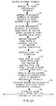
- the redundancy symbols are then appended to the sector address to form address code words (step 12).
- This generator polynomial is a distance twenty-six Reed-Solomon code generator polynomial that can correct up to twelve errors.
- the distance of a Reed-Solomon code is the minimum number of symbols that are dissimilar between any two code words. If two code words generated by a distance twenty-six Reed-Solomon code are compared, at least twenty-six of the symbols in the code words will not be the same. A code word in a distance twenty-six code and containing twelve or fewer errors can therefore be identified as the correct code word. The code word can be so identified because, with twelve or fewer errors, it is "closest" to, that is, has the largest number of symbols the same as, the correct code word.
- this principle is applied to the sector-seeking operation by comparing, symbol by symbol, the address code word read from the disk with the address code word for a specified address (steps 18-22). If the two code words differ in twelve [(d-1)/2] or fewer symbols, the sector is the specified sector; otherwise, it is determined not to be the specified sector (steps 24-28). Comparing the sector address code word with a specified address code word to determine the number of symbols that differ is much faster than conventional decoding and error correction techniques. Thus, using the comparison method, sector identification can be completed in time to perform a read or write operation in the data section of the sector if the sector is identified as the correct sector.
- Encoding the sector addresses into address code words does not necessarily prevent an address from being misinterpreted if the head is mis-synchronized with the address portion of a sector. If the head is mis-synchronized with a sector address code by some number, m, bits, the portion of the address code read from the sector is concatenated with m bits immediately preceding or following the address code, depending on how the head is mis-synchronized. This may result in an address code for one of the other sectors. Thus the sector could be incorrectly identified as the sector specified for a read or write operation.
- the redundancy symbols are further encoded by adding them to a coset leader to produce another set of redundancy symbols (step 14).
- the coset leader chosen is a code word of a super-code of the Reed-Solomon code.
- the coset leader chosen depends on the primitive polynomial used to generate the Galois Field.
- the coset leader, ⁇ is ⁇ 24 + ⁇ 30x23+ ⁇ 1x22+ ⁇ 12x21+ ⁇ 21x20 + ⁇ 4x19+ ⁇ 10x18+ ⁇ 3x17+ ⁇ 3x16+ ⁇ 10x15 + ⁇ 4x14+ ⁇ 21x13+ ⁇ 12x12+ ⁇ 1x11+ ⁇ 30x10+ x9
- the coset leader is added to the redundancy symbols in the sector address code word.
- the sector address symbols are not effected.
- adding the coset leader to the redundancy symbols in the code word in effect, shifts the entire group by an amount ⁇ .
- the code words are are shifted back by the same amount ⁇ to the original address code words. If, however, a code word is misread due to a mis-synchronization of the head, the result of subtracting the coset leader from the redundancy symbols will in no case result in the address code word for the specified sector.
- the new set of redundancy symbols resulting from coset leader addition are appended to the sector address to form header code words (step 14). These header code words are written in the address portion of the sectors during the formatting of the disk (step 16).
- the specified address of the sector is encoded to form an address code word as described above.
- the header code word of the sector rotating under the read/write head is read and the coset leader is subtracted, that is, it is again exclusive OR'd with the header code word (step 20).
- the resulting sector address code word is then compared with the address code for the specified sector address as set forth above to ascertain whether or not the sector is the specified sector (steps 22-28).
- the comparison will result in at least thirteen symbols which differ and the sector will not be identified as the specified sector. It will be appreciated by those skilled in the art that the same result may be achieved by adding the coset leader to the address code word for the specified address to form a specified header code word and then comparing this header code word with the header code word read from the disk.
- the disk drive When the disk drive is powered-up, that is, when the drive is made available to perform read or write operations, the drive must accurately locate the position of the head relative to the disk before any read or write operations can be performed. Therefore the system must read the header code of the sector rotating under the head and correctly interpret the code. If there are errors in the header code word, the sector might be identified incorrectly. Thus the system must first determine if there are errors in the address portion of the header code word, and if there are errors it corrects them, if possible, by means of error correction techniques.
- permutation decoding a technique known as permutation decoding is used to "decode" the sector address code word, that is, the header code word with the coset leader subtracted from it, to determine if there are any errors in the sector address and to correct them.
- Permutation decoding is an uncomplicated, fast error correction technique which is suitable for codes with high redundancy, i.e., codes which have a large number of redundancy symbols to correct a small number of errors. That is, permutation decoding corrects fewer errors for a given number of redundancy symbols than do other, more complicated error correction techniques.
- permutation decoding is preferred here because the address code words in fact contain a large number (e.g.
- redundancy symbols for the sector-seeking operation, as described above.
- the method of permutation used in this exemplary system is a variation of standard permutation decoding. Although this method corrects fewer errors then standard permutation decoding, it is faster than the standard method.
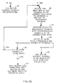
- a sector header code word is first read from the disk and the coset leader is subtracted from it, resulting in the corresponding address code word (steps 30-32).
- the six sector address symbols A ( Figure 2), are encoded with the generator polynomial to form the redundancy symbols (step 34). These redundancy symbols are then compared, that is, exclusive OR'd, with the redundancy symbols in the sector address code word (step 36).
- redundancy symbols differ by "t" or fewer symbols, where 1 ⁇ t ⁇ 12 and t represents the number of errors the code is designed to correct, there are no errors in the sector address contained in the address code word as retrieved from the disk and the position of the head relative to the disk is thus known (steps 38-40).
- the number "t" can have any value between one and twelve. However, the code can unconditionally correct only four or fewer errors using this error correction technique. If there are more than four errors, the code can correct them only if the errors are clustered such that at least six consecutive code word symbols are error-free.
- the next six symbols B in the sector address code word are encoded to form a set of redundancy symbols (steps 38, 42). These symbols are then compared with the corresponding symbols in the sector address code word (step 44). That is, the generated redundancy symbols are compared with symbols C, D, E and A ( Figure 3), where the redundancy symbols corresponding to A are at the low order end of the set of generated redundancy symbols. If the symbols differ by t or fewer symbols, the symbols in the set of generated redundancy symbols corresponding to the sector address symbols A are error-free (steps 46, 50). Thus these symbols are used as the correct sector address.
- step 48, 48a If such a set is not found in the sector address code word, the process is repeated with header code words of successive sectors until an error-free sector address can be determined (steps 48b, 52).
Landscapes
- Physics & Mathematics (AREA)
- Engineering & Computer Science (AREA)
- Mathematical Physics (AREA)
- General Physics & Mathematics (AREA)
- Pure & Applied Mathematics (AREA)
- Probability & Statistics with Applications (AREA)
- Algebra (AREA)
- Theoretical Computer Science (AREA)
- Signal Processing (AREA)
- Signal Processing For Digital Recording And Reproducing (AREA)
- Error Detection And Correction (AREA)
- Indexing, Searching, Synchronizing, And The Amount Of Synchronization Travel Of Record Carriers (AREA)
- Detection And Correction Of Errors (AREA)
Applications Claiming Priority (2)
| Application Number | Priority Date | Filing Date | Title |
|---|---|---|---|
| US70689 | 1987-07-07 | ||
| US07/070,689 US4847705A (en) | 1987-07-07 | 1987-07-07 | Method and apparatus for encoding magnetic disk sector addresses |
Publications (3)
| Publication Number | Publication Date |
|---|---|
| EP0349687A2 true EP0349687A2 (fr) | 1990-01-10 |
| EP0349687A3 EP0349687A3 (fr) | 1991-04-03 |
| EP0349687B1 EP0349687B1 (fr) | 1995-09-27 |
Family
ID=22096809
Family Applications (1)
| Application Number | Title | Priority Date | Filing Date |
|---|---|---|---|
| EP88306180A Expired - Lifetime EP0349687B1 (fr) | 1987-07-07 | 1988-07-07 | Méthode et appareil pour encoder les adresses des secteurs d'un disque magnétique |
Country Status (6)
| Country | Link |
|---|---|
| US (1) | US4847705A (fr) |
| EP (1) | EP0349687B1 (fr) |
| JP (1) | JPS6488966A (fr) |
| CA (1) | CA1324437C (fr) |
| DE (1) | DE3854526T2 (fr) |
| HK (1) | HK186595A (fr) |
Cited By (3)
| Publication number | Priority date | Publication date | Assignee | Title |
|---|---|---|---|---|
| EP0676762A3 (fr) * | 1994-04-05 | 1996-04-03 | Quantum Corp | Vérification d'en-tête au moyen d'une histoire de secteurs multiples. |
| EP0754341A4 (fr) * | 1995-02-02 | 2000-11-08 | Quantum Corp | Procede et dispositif de protection des donnees contre les erreurs dues aux defauts de synchronisation |
| EP0909484A4 (fr) * | 1996-11-14 | 2003-07-09 | Quantum Corp | Systeme de selection et de codage a code reed-solomon modifie |
Families Citing this family (13)
| Publication number | Priority date | Publication date | Assignee | Title |
|---|---|---|---|---|
| US5237574A (en) * | 1988-04-08 | 1993-08-17 | Digital Equipment Corporation | Error-resilient information encoding |
| JPH0821213B2 (ja) * | 1988-08-05 | 1996-03-04 | 富士通株式会社 | セクターサーボ情報検出方法 |
| US5068858A (en) * | 1989-12-21 | 1991-11-26 | International Business Machines Corporation | Error correction capability varied with track location on a magnetic or optical disk |
| US5388085A (en) * | 1993-03-03 | 1995-02-07 | International Business Machines Corporation | Apparatus and method for accessing sectors of a rotating disk |
| US5696775A (en) * | 1994-09-23 | 1997-12-09 | Cirrus Logic, Inc. | Method and apparatus for detecting the transfer of a wrong sector |
| KR100247064B1 (ko) * | 1997-04-10 | 2000-03-15 | 윤종용 | 콤팩트디스크-롬 드라이브의 디코딩장치에서 에러정정을 위한 메모리 리드회로 |
| US6438724B1 (en) | 1999-03-16 | 2002-08-20 | International Business Machines Corporation | Method and apparatus for deterministically altering cyclic redundancy check information for data storage |
| US6446234B1 (en) | 1999-03-16 | 2002-09-03 | International Business Machines Corporation | Method and apparatus for updating cyclic redundancy check information for data storage |
| US6463564B1 (en) * | 1999-09-14 | 2002-10-08 | Maxtor Corporation | Mis-synchronization detection system |
| JP2001126408A (ja) * | 1999-10-29 | 2001-05-11 | Sony Corp | 光学式回転記録媒体、アドレス情報記録方法、アドレス情報復元方法、光学式記録装置、光学式再生装置、および、光学式記録・再生装置 |
| US6640319B1 (en) * | 2000-08-29 | 2003-10-28 | Maxtor Corporation | Mis-synchronization detection system |
| KR20030017630A (ko) * | 2001-05-15 | 2003-03-03 | 코닌클리케 필립스 일렉트로닉스 엔.브이. | 정보 신호 내 보조 데이터 임베딩 |
| KR20040044448A (ko) * | 2001-08-20 | 2004-05-28 | 코닌클리케 필립스 일렉트로닉스 엔.브이. | 통지된 디코더를 위한 향상된 코딩 |
Family Cites Families (3)
| Publication number | Priority date | Publication date | Assignee | Title |
|---|---|---|---|---|
| US4413339A (en) * | 1981-06-24 | 1983-11-01 | Digital Equipment Corporation | Multiple error detecting and correcting system employing Reed-Solomon codes |
| EP0248536B1 (fr) * | 1986-05-31 | 1992-07-22 | Sony Corporation | Procédés et appareil pour chercher une adresse but sur un milieu d'enregistrement |
| CA1299743C (fr) * | 1986-08-26 | 1992-04-28 | Wataru Sakagami | Support d'enregistrement d'information a en-tete comportant un code de correction d'erreurs pour chaque bloc et methode d'enregistrement d'information sur ce support |
-
1987
- 1987-07-07 US US07/070,689 patent/US4847705A/en not_active Expired - Lifetime
-
1988
- 1988-07-06 CA CA000571261A patent/CA1324437C/fr not_active Expired - Fee Related
- 1988-07-07 JP JP63170012A patent/JPS6488966A/ja active Granted
- 1988-07-07 DE DE3854526T patent/DE3854526T2/de not_active Expired - Fee Related
- 1988-07-07 EP EP88306180A patent/EP0349687B1/fr not_active Expired - Lifetime
-
1995
- 1995-12-07 HK HK186595A patent/HK186595A/en not_active IP Right Cessation
Cited By (4)
| Publication number | Priority date | Publication date | Assignee | Title |
|---|---|---|---|---|
| EP0676762A3 (fr) * | 1994-04-05 | 1996-04-03 | Quantum Corp | Vérification d'en-tête au moyen d'une histoire de secteurs multiples. |
| US5568627A (en) * | 1994-04-05 | 1996-10-22 | Quantum Corporation | Header verification in a disk drive using sector histories for improved format efficiency |
| EP0754341A4 (fr) * | 1995-02-02 | 2000-11-08 | Quantum Corp | Procede et dispositif de protection des donnees contre les erreurs dues aux defauts de synchronisation |
| EP0909484A4 (fr) * | 1996-11-14 | 2003-07-09 | Quantum Corp | Systeme de selection et de codage a code reed-solomon modifie |
Also Published As
| Publication number | Publication date |
|---|---|
| CA1324437C (fr) | 1993-11-16 |
| EP0349687A3 (fr) | 1991-04-03 |
| EP0349687B1 (fr) | 1995-09-27 |
| JPH0572030B2 (fr) | 1993-10-08 |
| DE3854526D1 (de) | 1995-11-02 |
| DE3854526T2 (de) | 1996-03-14 |
| US4847705A (en) | 1989-07-11 |
| HK186595A (en) | 1995-12-15 |
| JPS6488966A (en) | 1989-04-03 |
Similar Documents
| Publication | Publication Date | Title |
|---|---|---|
| US4847705A (en) | Method and apparatus for encoding magnetic disk sector addresses | |
| EP0248536B1 (fr) | Procédés et appareil pour chercher une adresse but sur un milieu d'enregistrement | |
| JP3405712B2 (ja) | データ回復方法およびデータ記憶装置 | |
| EP0335529B1 (fr) | Méthode et appareil de codage et de mappage des secteurs d'adresse d'un disque magnétique | |
| JP3440952B2 (ja) | データ記録方法及びデータ再生方法 | |
| US4862295A (en) | Method of formatting a storage medium and drive unit for controlling the reading and writing of data on the formatted storage medium | |
| JP2003141822A (ja) | データ記憶装置、読み出しデータの処理装置および読み出しデータの処理方法 | |
| US4796110A (en) | System and method for encoding and storing digital information on magnetic tape | |
| US7178086B2 (en) | Direct partial update of CRC/ECC check bytes | |
| US5237574A (en) | Error-resilient information encoding | |
| JPS62217468A (ja) | デイジタル情報の記録/再生方法及び装置 | |
| JP4219092B2 (ja) | 多重ワード情報を符号化する方法、デバイスおよび担体 | |
| US5265104A (en) | Data storage system including redundant storage devices | |
| WO1998016919A1 (fr) | Procede permettant d'assurer l'integrite des donnees a l'aide d'une unite de calcul d'adresse | |
| US4914535A (en) | Synchronization for stored data | |
| US4675870A (en) | Method of and apparatus for decoding a data stream which is protected by a multi-symbol error protection code | |
| US4989211A (en) | Sector mis-synchronization detection method | |
| US6769088B1 (en) | Sector-coding technique for reduced read-after-write operations | |
| JP4527255B2 (ja) | 同期エラーを検出するためのシステムおよび方法 | |
| US7131052B2 (en) | Algebraic decoder and method for correcting an arbitrary mixture of burst and random errors | |
| USRE34003E (en) | Method and apparatus for encoding and mapping magnetic disk sector addresses | |
| US5781567A (en) | Digital coding method and apparatus for the correction of burst errors | |
| EP0365634B1 (fr) | Procede et appareil pour encodage consistant a former un mot code par combinaison d'une premiere sequence de code avec une seconde sequence de code | |
| US5521929A (en) | Robust and redundant physical block identification scheme for data storage devices | |
| US7185263B2 (en) | Method of joint decoding of possibly mutilated code words |
Legal Events
| Date | Code | Title | Description |
|---|---|---|---|
| PUAI | Public reference made under article 153(3) epc to a published international application that has entered the european phase |
Free format text: ORIGINAL CODE: 0009012 |
|
| AK | Designated contracting states |
Kind code of ref document: A2 Designated state(s): DE FR GB IT NL SE |
|
| 17P | Request for examination filed |
Effective date: 19900104 |
|
| PUAL | Search report despatched |
Free format text: ORIGINAL CODE: 0009013 |
|
| AK | Designated contracting states |
Kind code of ref document: A3 Designated state(s): DE FR GB IT NL SE |
|
| RHK1 | Main classification (correction) |
Ipc: G11B 20/18 |
|
| 17Q | First examination report despatched |
Effective date: 19930318 |
|
| RAP1 | Party data changed (applicant data changed or rights of an application transferred) |
Owner name: QUANTUM CORPORATION |
|
| GRAA | (expected) grant |
Free format text: ORIGINAL CODE: 0009210 |
|
| AK | Designated contracting states |
Kind code of ref document: B1 Designated state(s): DE FR GB IT NL SE |
|
| REF | Corresponds to: |
Ref document number: 3854526 Country of ref document: DE Date of ref document: 19951102 |
|
| ITF | It: translation for a ep patent filed | ||
| PG25 | Lapsed in a contracting state [announced via postgrant information from national office to epo] |
Ref country code: SE Effective date: 19951227 |
|
| ET | Fr: translation filed | ||
| PLBE | No opposition filed within time limit |
Free format text: ORIGINAL CODE: 0009261 |
|
| STAA | Information on the status of an ep patent application or granted ep patent |
Free format text: STATUS: NO OPPOSITION FILED WITHIN TIME LIMIT |
|
| 26N | No opposition filed | ||
| PGFP | Annual fee paid to national office [announced via postgrant information from national office to epo] |
Ref country code: FR Payment date: 19980618 Year of fee payment: 11 |
|
| PGFP | Annual fee paid to national office [announced via postgrant information from national office to epo] |
Ref country code: NL Payment date: 19980629 Year of fee payment: 11 |
|
| PG25 | Lapsed in a contracting state [announced via postgrant information from national office to epo] |
Ref country code: FR Free format text: THE PATENT HAS BEEN ANNULLED BY A DECISION OF A NATIONAL AUTHORITY Effective date: 19990731 |
|
| PG25 | Lapsed in a contracting state [announced via postgrant information from national office to epo] |
Ref country code: NL Free format text: LAPSE BECAUSE OF NON-PAYMENT OF DUE FEES Effective date: 20000201 |
|
| NLV4 | Nl: lapsed or anulled due to non-payment of the annual fee |
Effective date: 20000201 |
|
| REG | Reference to a national code |
Ref country code: FR Ref legal event code: ST |
|
| PGFP | Annual fee paid to national office [announced via postgrant information from national office to epo] |
Ref country code: DE Payment date: 20010620 Year of fee payment: 14 |
|
| PGFP | Annual fee paid to national office [announced via postgrant information from national office to epo] |
Ref country code: GB Payment date: 20010621 Year of fee payment: 14 |
|
| REG | Reference to a national code |
Ref country code: GB Ref legal event code: IF02 |
|
| PG25 | Lapsed in a contracting state [announced via postgrant information from national office to epo] |
Ref country code: GB Free format text: LAPSE BECAUSE OF NON-PAYMENT OF DUE FEES Effective date: 20020707 |
|
| PG25 | Lapsed in a contracting state [announced via postgrant information from national office to epo] |
Ref country code: DE Free format text: LAPSE BECAUSE OF NON-PAYMENT OF DUE FEES Effective date: 20030201 |
|
| GBPC | Gb: european patent ceased through non-payment of renewal fee |
Effective date: 20020707 |
|
| PG25 | Lapsed in a contracting state [announced via postgrant information from national office to epo] |
Ref country code: IT Free format text: LAPSE BECAUSE OF NON-PAYMENT OF DUE FEES;WARNING: LAPSES OF ITALIAN PATENTS WITH EFFECTIVE DATE BEFORE 2007 MAY HAVE OCCURRED AT ANY TIME BEFORE 2007. THE CORRECT EFFECTIVE DATE MAY BE DIFFERENT FROM THE ONE RECORDED. Effective date: 20050707 |