EP0349977A2 - Vorrichtung zur Navigation eines Fahrzeuges - Google Patents
Vorrichtung zur Navigation eines Fahrzeuges Download PDFInfo
- Publication number
- EP0349977A2 EP0349977A2 EP89112192A EP89112192A EP0349977A2 EP 0349977 A2 EP0349977 A2 EP 0349977A2 EP 89112192 A EP89112192 A EP 89112192A EP 89112192 A EP89112192 A EP 89112192A EP 0349977 A2 EP0349977 A2 EP 0349977A2
- Authority
- EP
- European Patent Office
- Prior art keywords
- vehicle
- node
- nodes
- road
- candidate
- Prior art date
- Legal status (The legal status is an assumption and is not a legal conclusion. Google has not performed a legal analysis and makes no representation as to the accuracy of the status listed.)
- Granted
Links
Images


Classifications
-
- G—PHYSICS
- G01—MEASURING; TESTING
- G01C—MEASURING DISTANCES, LEVELS OR BEARINGS; SURVEYING; NAVIGATION; GYROSCOPIC INSTRUMENTS; PHOTOGRAMMETRY OR VIDEOGRAMMETRY
- G01C21/00—Navigation; Navigational instruments not provided for in groups G01C1/00 - G01C19/00
- G01C21/26—Navigation; Navigational instruments not provided for in groups G01C1/00 - G01C19/00 specially adapted for navigation in a road network
- G01C21/28—Navigation; Navigational instruments not provided for in groups G01C1/00 - G01C19/00 specially adapted for navigation in a road network with correlation of data from several navigational instruments
- G01C21/30—Map- or contour-matching
Definitions
- This invention relates to a navigation apparatus, and, more specifically, to a vehicle navigation apparatus of the type which helps to guide a vehicle while matching the current vehicle position conjectured by the dead-reckoning method with the road as depicted on a map stored previously.
- a dead-reckoning method has come to be used in the field of vehicle navigation.
- a current vehicle position is conjectured on the basis of information on the vehicle travel direction obtained by utilizing geomagnetism and the integrated travel distance.
- the current vehicle position conjectured by the method is displayed on a display screen along with a map representing the area around the position. It is said to be a problem with this method that it can involve accumulation of measurement errors.
- map matching As described in Japanese Patent Laid-Open No. 61-209316, this map matching method consists in correcting the conjectured current vehicle position to a position on a road map which exhibits a peculiar road configuration, such as an intersection, at the time when the vehicle is judged to have passed that position (The operation is referred to as map matching).
- this map matching method is also based on the dead-reckoning method. Furthermore, peculiar points such as intersections cannot always be expected to exist. It can happen that two adjacent peculiar points are separated from each other by such a distance that measurement errors accumulate in the interval from one to the other to an excessive degree, so that map matching cannot be conducted any more due to the accumulated measurement errors. Attempting to perform map matching in such cases may result in the current position being erroneously map-matched onto a road other than the one on which the vehicle is actually running. Once the current vehicle position has been map-matched onto the wrong road, it is impossible to effect correct map matching thereafter.
- the inventors of the present invention developed a map-matching method in which map matching can be reliably conducted without depending on such unreliable points as intersections, which cannot always be expected to exist, and then filed patent applications for the method in the name of the assignee (e.g., the U.S. patent application titled “Apparatus for Navigating Vehicle", filed on April 25, 1989, and Japanese Patent Application No. 63-106556).
- This method comprises a combination of the dead-reckoning and map-matching methods, and further employs a plurality of nodes which are arranged along the roads on a map and used as data. Coordinate positional information is assigned to each of these nodes.
- Japanese Patent Application No. 63-106556 solved this problem by developing a control method comprising a procedure for finding a target node when the vehicle concerned is considered to be traveling on a memory road, a procedure for making a judgment as to whether the vehicle is traveling on a road which is not stored in memory (hereinafter referred to as a "non-memory road”), a procedure for finding a target node when the vehicle is traveling on a non-memory road, and a procedure for making a judgment as to whether or not the vehicle has been restored to a memory road.
- a control method comprising a procedure for finding a target node when the vehicle concerned is considered to be traveling on a memory road, a procedure for making a judgment as to whether the vehicle is traveling on a road which is not stored in memory (hereinafter referred to as a "non-memory road"), a procedure for finding a target node when the vehicle is traveling on a non-memory road, and a procedure for making a judgment as
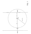
- the vehicle is judged to be traveling on a non-memory road, the distance Lx between the point (referred to as Px) at which it is considered to have deviated from a memory road and the current position (referred to as Po) conjectured by the dead-reckoning method, is calculated, the target node being searched for on the basis of this distance.
- Such nodes will be hereinafter referred to as “candidate nodes”.
- the distance Lx′ from the current position Px to each candidate node is calculated.
- a certain threshold H i.e., Lx′ ⁇ H
- that candidate node is regarded as the node to be reached.
- the solid line represents a memory road
- the dashed line a non-memory road.
- the target node is specified, when the vehicle is running on a non-memory road, from among candidate nodes that can be reached, on the basis of the distances Lx′ between the current position and the respective candidate nodes.
- this method simply depends on the comparison of the respective distances Lx′ and the threshold H, resulting in rather low accuracy in specifying the target node. Accordingly, it can happen that the wrong node is specified as the target node to be reached when the vehicle is restored to a memory road, which makes it impossible to continue dead reckoning and map mapping thereafter.
- the present invention has been contrived with a view to eliminating the above-mentioned problems experienced with the prior art and the prior applications. It is accordingly an object of this invention to provide a vehicle navigating apparatus in which the storage capacity for map matching data is reduced, thereby making it possible, while admitting the existence of non-memory roads, to improve the accuracy in specifying the point on a memory road to which a vehicle, traveling on a non-memory road, is to be restored.
- This invention further aims at providing a vehicle navigation apparatus which allows the map-matching travel to be reliably continued after the vehicle has been restored to a memory road.
- a navigation apparatus comprising: a conjecture means for conjecturing the current position of a vehicle by the dead-reckoning method on the basis of the vehicle travel direction and vehicle travel distance, a node storage means for storing road information in the form of the positions of a plurality of nodes provided on the roads concerned, a non-memory road judging means for making a judgment as to whether or not the road on which the vehicle is running is one which is stored in the above-mentioned storage means, and a target node specifying means for specifying, when the vehicle is judged by the above-mentioned non-memory road judging means to be traveling on a road which is not stored in the above-mentioned node storage means, the node to be reached when the vehicle is restored to a memory road, on the basis of the respective directions in which lie the current position conjectured by the above-mentioned conjecture means and the nodes stored in the above-mentioned node
- the navigation apparatus of this invention admits the existence of non-memory roads, thus making it possible to reduce the storage capacity for the node information.
- the apparatus continues, while the vehicle is traveling on a non-memory road, to conjecture the destination node on the basis of the respective directions in which lie the current position and the nodes stored in memory and of the vehicle travel direction, so that any point on a memory road to which the vehicle is restored can be specified more accurately.
- the node storage means further stores the connective relationship between the nodes
- the non-memory road judging means includes a first candidate node extracting means for extracting from the node storage means a plurality of nodes connected to a start node as target candidate nodes, a first node deleting means for identifying from among the candidate nodes those nodes which cannot be the target node by comparing the respective directions in which the current vehicle position and these candidate nodes lie with the vehicle travel direction and for deleting the nodes thus identified from the candidate nodes, and a determining means for judging the vehicle to be running on a non-memory road when the number of candidate nodes has been reduced to zero as a result of the node deletion effected by the above-mentioned first node deleting means.
- those nodes which are not likely to be the target node are deleted through elimination, while the vehicle is running on a memory road, from the candidate nodes, thereby making it possible to make a correct judgment as to whether or not the vehicle is running on a non-memory road.
- the node storage means further stores the connective relationship between the nodes
- the target node specifying means includes a search area setting means for setting the search area corresponding to the travel distance covered by the vehicle from the time when the vehicle is judged to be running on a non-memory road to the present, a second candidate node extracting means for extracting a plurality of nodes existing within this search area as target candidate nodes, and a second node deleting means for narrowing down the candidate node choice range by identifying, from among the candidate nodes, those nodes which cannot be the target node on the basis of the respective directions in which lie the current position and the respective candidate nodes and of the vehicle travel direction and by deleting the nodes thus identified from the candidate nodes.
- the connective relationship between the nodes cannot be utilized in narrowing down the candidate node choice range while the vehicle is running on a non-memory road, so that a search area for the candidate nodes is set, and the nodes within this search area are extracted as target candidate nodes. That node which is closest to the destination is gradually specified through elimination from among these candidate nodes.
- the above-mentioned search area consists of a circle having a radius which is in proportion to the total travel distance covered by the vehicle from the time when the vehicle is judged to be running on a non-memory road to the present.
- the radius of the above-mentioned circle corresponds to a value obtained by multiplying by a constant which is one or less the travel distance covered by the vehicle from the time at which it is judged to be running on a non-memory road to the present.
- an upper and a lower limit are established to the radius of the above-mentioned circle.
- the target node specifying means includes an average travel direction storage means for storing the average of the travel directions for the respective travel distance units covered, and an angle difference calculating means for calculating, when the vehicle is judged by the non-memory road judging means to be running on a non-memory road, the average value, for the respective candidate nodes, of the angle differences between the data on the directions in which lie the current vehicle position and these candidate nodes and the stored data on a plurality of average travel directions for the respective travel distance units, the above-mentioned second deleting means deleting from the candidate nodes those nodes which involve an angle difference exceeding a first predetermined value.
- the target node search when the vehicle is running on a non-memory road is performed through elimination taking into account the travel process in the past.
- the above-mentioned target node specifying means includes a control means for operating the above-mentioned search area specifying means and the second candidate node extracting means, the average of the angle differences of any new candidates detected by the second candidate node extracting means when a new search area is set by the above-mentioned search area specifying means being calculated by the above-mentioned angle distance calculating means using the average travel direction data stored in memory after the time when these new candidate nodes are detected.
- the judgment as to whether or not a new candidate node found during the target node search when the vehicle is traveling on a non-memory road is a target node is made using the travel distance data stored in memory after the time when that new candidate node is detected, so that the evaluation of that new candidate node is not affected by the travel process in the past.
- This form of apparatus is effective when the non-memory road concerned is actually curved to a large degree.
- the target node specifying means has a map-matching means for map-matching the current vehicle position onto a specified node.
- the above-mentioned map matching means performs map matching when the distance between the node specified by the target node specifying means and the current vehicle position is not larger than a second predetermined value.
- the apparatus is further equipped with a means for judging the vehicle to have been restored to a memory road when a node is specified by the above-mentioned target node specifying means.
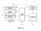
- Fig. 2 shows a control system configuration of a vehicle navigation apparatus in accordance with this embodiment.
- This navigation apparatus 10 comprises a geomagnetism sensor 10 for detecting the travel direction (D M ) of the vehicle, a vehicle velocity sensor 12 adapted to output a pulse signal R EV for each rotation of the wheels, a map information storage device 13 storing map information including graphic image data such as a map representing geographical information on roads and buildings and node information on nodes allocated to the roads and buildings, a display 14 consisting of a CRT, etc. and adapted to display road information as the geographical information stored in the above-mentioned map information memory 13, and a control circuit 15 for controlling these.
- D M travel direction
- R EV pulse signal
- This control circuit 15 includes an arithmetic circuit 16, a storage circuit 17 connected thereto, and an I/O interface 18, the geomagnetism sensor 11, the vehicle velocity sensor 12, the map information memory 13 and the display 14 being connected to the above-mentioned arithmetic circuit 16 through the I/O interface 18.
- a signal indicative of the vehicle travel direction transmitted from the geomagnetism sensor 11 and a signal indicative of the vehicle travel distance transmitted from the vehicle velocity sensor 12 are input through the I/O interface 18 to the arithmetic circuit 16.
- the estimated current vehicle position is then calculated in the arithmetic circuit 16, the result of the calculation being temporarily stored in the storage circuit (RAM) 17.
- the control circuit 15 extracts beforehand the graphic image of the map representing the area concerned and the node information from the map information memory 13. Map matching is periodically conducted; when no map matching is conducted, the display 14 represents on its screen the conjectured vehicle current position detected in the manner described above. When map matching is conducted, it represents the corresponding estimated current vehicle position matched onto the map.
- the map information memory 13 may consist, for example, of a CD-ROM and a CD drive (player) for CD-ROM reproduction.
- map information to be stored in the above-described map information memory 13 a multitude of nodes are provided for the roads, the respective positions of the nodes being previously stored in memory along with data showing the connective relationship between the nodes. These nodes are provided not only at intersections, corners, etc., but also on straight roads at predetermined intervals.
- Figs. 3A and 3B show the relationship between the roads and the nodes arranged thereon.
- Fig. 3A shows, by way of example, a lattice-like road arrangement, nodes N 0 to N 8 being provided at the intersection of these roads.
- the map information memory 13 stores the positional coordinates of these nodes as well as the connective relationship for each node showing how it is connected to the others. This relationship is represented, in the case of node N 0 in Fig. 3A, as links between this node N 0 and those nodes which are directly connected thereto (i.e., primary connection).
- Fig. 3B shows the connective relationship as seen from the node N 0 .
- Fig. 4 shows how the flags, intermediate data, etc. used for controlling the apparatus of this embodiment are stored in the RAM.
- the character D M represents the magnetic declination of the geomagnetism currently read.
- Stored in D P is the average of the geomagnetism values that have been read.
- the values D P0 , D P1 , «, D Pi , hence, D Pn constitute an array of the geomagnetism values D P successively stored in memory as the vehicle moves along.
- the geomagnetism D M is measured 32 times to obtain the average of the D P values.
- D P (1)
- P x indicates the assumed current vehicle position calculated by the dead-reckoning method, and P D the display vehicle position to be displayed on the display 14.
- P C indicates a position where a corner passed by the vehicle is recognized as such.
- P L denotes a position where the vehicle is judged to have deviated from a memory road, and P I a position where a virtual node, which is described below, is set.
- the section N I stores the ID number of the virtual node, and the character N L represents the ID number of the node reached by the vehicle last.
- F N represents the flag for indicating that a virtual node is being set, and F C is the corner detecting flag; each time the vehicle passes a corner on the road, this is detected and recorded by the flag F C .
- the character F D and F A indicate the corner approach flag and the node arrival flag; each time the vehicle approaches a corner or arrives at a node, this is detected and recorded by the flag F D or F A .
- N j D CLj and I Xj form an array of candidate nodes when the vehicle is running on a memory road, each element being retrieved by the index j.
- N j represents the respective names of the candidate nodes
- D CLj the direction toward the j-th node as counted from the node the vehicle has reached last
- I Xj the residual distance between the current vehicle position P X and the j-th candidate node.
- N k , D CIj and I Xk form a list of candidate nodes when the vehicle is running on a non-memory road, each element being retrieved by the index k.
- N k represents the respective ID numbers of the candidate nodes
- D CIk the data on the direction in which virtual node and the k-th node lie
- I Xk the residual distance between the current vehicle position P X and the k-th candidate node.
- the character C k indicates the number of D P used for evaluating the respective candidate nodes.
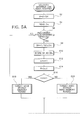
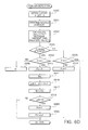
- Fig. 5 is a flowchart showing the process of navigation control in its entirety.
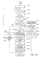
- Figs. 6B and 6C are program flowcharts for the node search when the vehicle is traveling on a non-memory road.
- Fig. 6D is a program flowchart for the corner detection control
- Fig. 6E is a program flowchart for the map-matching control.
- the program of Fig. 5 is an interrupt routine started each time an R EV pulse from the vehicle sensor 12 is input.
- Step S2 the vehicle travel distance d is updated.
- the pulse R EV is generated for each rotation of the wheels.
- one rotation of the wheels causes the vehicle to advance 0.4m.
- d d + 0.4 (2)
- Step S4 the magnetic declination D M is read by means of the geomagnetism sensor 11. It is examined in Step S6 to see whether the operations of Steps S2 and S4 have been conducted 32 times. If the result in Step S6 is negative, the target node search is not conducted, the procedure returning from Step S6 to the main routine.
- Step S8 Since the vehicle advances 40cm for each R EV interruption, it advances 12.8m when the interruption is repeated 32 times. In other words, the control procedures of Step S8 and thereafter are started each time the vehicle advances 12.8m.
- the number of times is not limited to 32; it can be changed in accordance with the wheel size.
- Step S10 the D P obtained in Step S8 is stored in a series of values D Pn .
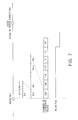
- This series of values constitutes an array for storing the D P values calculated for each 12.8m advancement of the vehicle from the node it reached last to the next one. This array will be explained with reference to Fig. 7.
- the average of magnetic declination calculated at the last node is D PO
- the number of D Pn values increases, as D P1 , D P2 ,.... as the vehicle moves away from the node.
- the number of D P values stored is recorded by a counter n, which is incremented in Step S12.
- Step S14 the current vehicle position P x (x, y) conjectured in accordance with the dead reckoning method is calculated on the basis of the travel distance d and D P . It is examined in Step S16 to see whether the vehicle is traveling on a memory road from the flag F ON .
- node N 0 is the node that the vehicle has reached last; the node is directly linked with nodes N 1 , N 7 and N 5 , the vehicle actually moving toward node N 7 .
- the travel direction data D P0 to D P5 are calculated before the vehicle have reached the current position P x (x, y).
- the nodes N 1 , N 7 and N5 can be nominated at the time when the vehicle reaches node N 0 on the basis of the stored inter node connective relationship (see Fig. 3B) which serves to indicate the nodes to which the vehicle can move directly.
- Such nodes will be referred to as "candidate nodes"
- the connective relationships between nodes N 0 and N 1 , N 0 and N 7 , and N 0 and N 5 are respectively known beforehand as the connecting directions D CO1 , D CO7 and D C05 .
- the vehicle travel direction D P is compared with the inter-node connecting direction D C with respect to each candidate node, specifying that candidate node which is relatively close to the destination as the destination node. In this embodiment, in particular, this comparison is performed on the basis of an evaluation function T j .
- ⁇ i
- j indicates the j-th candidate node
- D CLj represents the value of the data regarding the direction of the connection between the node N L at which the vehicle arrived last and the candidate node N j .
- the above ⁇ is calculated with respect to i on the values of D Pi stored before the vehicle reaches the current position P.
- the division by n is performed for the purpose of obtaining the average value of the differences between the respective stored travel direction values D PO ..., D Pn and the respective connecting direction values D C .
- the smaller the value of this evaluation function T j the closer the candidate node to the destination node.
- T 1 1/6 ⁇ (D P0 - D CO1 ) + (D P1 - D CO1 ) + (D P2 - D CO1 ) + (D P3 - D CO1 ) + (D P4 - D CO1 ) + (D P5 - D CO1 ) + (D P6 - D CO1 ) ⁇ (5)
- T 7 1/6 ⁇ (D P0 - D CO7 ) + (D P1 - D CO7 ) + (D P2 - D CO7 ) + (D P3 - D CO7 ) + (D P4 - D CO7 ) + (D P5 - D CO7 ) + (D P6 - D CO7 ) ⁇ (6)
- T 5 1/6 ⁇ (D P0 - D CO5 )
- the above-mentioned weight W exhibits characteristic values as shown in Fig. 9 in accordance with the difference ⁇ between the connecting direction D C and the travel direction D P .
- the greater the direction difference ⁇ the larger the value of the weight W.
- the greater the direction difference ⁇ of a candidate node the less likely is the node to be the target node, so that such a node should be deleted from the candidates as soon as possible.
- Step S18 the node search subroutine in Step S18 to be performed when F ON is "1" in Step S16 will be described in detail with reference to Fig. 6A.
- Step S100 the arrival flag F A is set to "0". This flag is set to "1" when the vehicle reaches the next node (Step S132).
- Step S108 The loop formed by Steps S104 through S126 via S108 is applicable to each of the candidate nodes nominated by j.
- the evaluation function T j of equation (3) is calculated in Steps S104 and S106 with respect to the j-th node.
- Step S108 the value of T j is compared with the threshold K.
- T j > K (8) this j-node is not to be regarded as the destination node, so that it is deleted from the candidate node list in Step S109. Whether the number of candidate nodes has been reduced to "0" is examined in Step S110. Explanation regarding this point will be given below.
- Step S108 If the comparison result in Step S108 is judged to be: T j ⁇ K, (9) this j-node can be considered not to be so deviated from the travel direction D P that it should be deleted from the candidates at this stage. Accordingly, the node is not deleted.
- the procedure then moves on to Step S120, where the distance I Xj between the current vehicle position P X (x, y) and the j-node is calculated. It is examined in Step S122 to see whether the distance I Xj has been reduced to a value not larger than 0. If I Xj is 0 or less, it implies that the j-node is the destination node.
- Step S126 If the result of Step S126 is affirmative, the procedure returns to the main routine of Fig. 5.
- the corner detection subroutine of Step S22 is then executed to detect corners (as will be described below in detail), map matching being executed in Step S24.
- display in one of the following modes (a) to (c) is effected in Step S26:
- Fig. 7 shows how the number of candidate nodes, which is 20 at first, is diminished one by one.
- Step S122 If the vehicle continues to travel on memory a road, it will sooner or later arrive at a node where I Xj ⁇ 0 (Step S122). In that case, the procedure moves on to Step S130, where the node at which I Xj ⁇ 0 is added to the arrival node list. Thus, a list of the nodes which the vehicle has passed up to the present is prepared in this Step S130.
- Step S132 Flag F A indicating that the vehicle has reached a node is set to "1". As will be stated below, this Flag F A is utilized in map matching.
- Step S134 the latest arrival node N L is updated, and, in Step 136, the counter n is set to "0".
- Step 138 the road information such as the connective relationship with respect to the node N L reached by the vehicle last, is examined obtaining the connective relationship (Fig. 3B) and the connecting direction D C to prepare a candidate node list (Fig. 4).
- Step S110 the number of candidate nodes is judged in Step S110 to have been reduced to 0 as a result of the repetition of the procedure of Step S109 in which the operation of deleting those nodes at which T j ⁇ K is performed.
- Flag F ON is set to "0" in Step S112 (see Fig. 7). That is, the vehicle is judged to be running on a non-memory road at the time when the number of candidates has become 0.
- Step S113 the current vehicle position P X (x, y) is stored as the position P L (x, y) at which the vehicle has deviated from a memory road.
- the storage of map information on smaller roads may be intentionally omitted with a view to saving memory capacity.
- nodes are generally provided on purpose at branch points where memory roads and non-memory roads part from each other.
- nodes cannot always be expected to exist at branch points mentioned above. This is why the point P X is stored in memory as the point P L .
- the control procedure then returns to the main routine.
- F ON is reset when the number of candidate nodes, 20 at first, has been reduced to "0".
- Step S8 When the vehicle has traveled another 12.8m after thus storing in memory the point at which it left a memory road last (Steps S2 to S6), the travel direction D P as from the point P L is calculated in Step S8, and the current vehicle position P X (x, y) is calculated in Step S14, executing the node search subroutine of Fig. 6B.
- this node P X0 is established as a "virtual node".
- the virtual node N 1 is established at the point P X0 .
- "establishing a virtual node” means storing the position of that virtual node in the RAM 17 and registering it in a retrievable manner.
- the respective connecting directions D CIk as seen from this virtual node N 1 to real nodes are calculated.
- the k denotes the index for retrieving real nodes.
- the calculation of D CIk is performed on the basis of the current vehicle position P X conjectured by the dead-reckoning method and the coordinate values of the real nodes existing in the circle. Since the vehicle is relatively likely to reach one of these nodes existing in the circle, the nodes will be referred to as "candidate nodes" as in the memory road node search.
- the elimination algorithm adopted in deleting those nodes which are not likely to be the destination node from these candidate nodes substantially resembles that adopted in the memory road node search described above.
- T 1 W x
- (14) and T 2 W x
- the value of this threshold K′ differs from that of the threshold K adopted in the memory road node search described above.
- the value of K′ is determined such that K′ ⁇ K.
- T 1 1/2 ⁇ W
- T 2 1/2 ⁇ W
- T 1 1/3 ⁇ W
- T 2 1/3 ⁇ W
- the denominator C k in the above evaluation equation constitutes, as in the memory road node search, the number of D P as seen from P L . It is to be noted, in this regard, that, in the case of the non-memory road node search, the number of candidate nodes constitutes a problem.
- the next target node is logically always sure to exist within the above-mentioned circle having the radius r 1 calculated at first. If, however, the vehicle is running on a non-memory road, there is no guarantee of the target node existing within the circle having the radius r 1 .
- Step S150 the node arrival flag F A is reset in Step S150.
- Step S151 the total travel distance L X covered by the vehicle between the point P L at which the vehicle has left a memory road and the current vehicle position P X is calculated
- the radius r will be enlarged as the travel distance L X increases, resulting in the number of candidate nodes becoming larger and larger.
- the following range is set for the value of r: 50m ⁇ r ⁇ 500m (18)
- Step S154 If, in Step S154, no nodes are judged to be in the search area, the flag F N is examined in Step S156. This flag F N serves to indicate that a virtual node is being set. If no virtual node is being set, the procedure moves on to Step S158, deleting the D PI stored in Step S10 (Fig. 5). This is effected the previous travel direction data may be ignored until a virtual node has been set. After that, the procedure returns to the main routine.
- Step S160 If some nodes are found in the circle in Step S154, the procedure moves on to Step S160, where it is checked to see whether the flag F N is set.
- the virtual node N 1 is established in Step S164 only then when the flag is not set in Step S 162. That is, the flag F N is set in Step S164, and, in order to set the virtual node N I at the current vehicle position P X in Step S164, the point P X is established as the virtual node point P 1 .
- Step S166 the real nodes found in Step S154 are established as candidate nodes N k , preparing a connective relationship list of the respective connections between these candidate nodes N k and the virtual node N I .
- Step S168 The connecting direction data D CIk on the connection between the k-th candidate node N k and the virtual node N I is prepared for each of the candidate nodes found within the circle.
- the counter C k for each of the candidate nodes N k is initialized to 1, the procedure then returning to the main routine.
- the flag F N indicating that a virtual node has been established is set is set to 1.
- Step S154 When the vehicle has advanced another 12.8m and the procedure has moved on to Step S154, it is examined to see whether or not any nodes exist within the circle whose radius r is calculated in Step S152. Generally speaking, the same nodes as previously found are likely to be found again. In that case, the procedure moves from Step S160 to Step S174 to examine to see whether the nodes discovered include any new ones added to the previously detected candidate nodes. If no new nodes are included, the procedures moves to Step S182, incrementing the counter C k for storing the number of travel direction data pieces D P that should be evaluated. In the case of the example shown in Fig.
- Step S180 or Step S182 of Fig. 6B the procedure moves on to Step S190 of Fig. 6C.
- Step S190 the subscript k nominating the candidate nodes is initialized. Every one of the candidate nodes is evaluated as the target node through the loop: Step S192 ⁇ Step S204 ⁇ Step S192.
- the evaluation function T k is calculated for the candidate node N k on the basis of the latest travel directions D Pi of the number corresponding to that retained by the counter C k of this candidate node, in accordance with equation (12):
- This T k is then compared with the threshold K′ in Step S196, making a judgment as to whether or not this candidate node N k should be deleted.
- Step S198 the distance I Xk between the current position P X (x, y) and the candidate node concerned is calculated in Step S198, making a judgement in Step S200 as to whether or not the vehicle has come to a position close enough to that candidate nodes. If not, the procedure moves on in the order: Step S202 ⁇ , Step S204 ⁇ Step S192, repeating the above control operation.
- Step S196 If, in Step S196, T k > K′, that candidate node k is deleted from the candidate node list in Step S230. If, in Step S232, some candidate node still remain, the procedure moves to Step S202, performing the above control operation.
- Step S200 I Xk ⁇ 0
- the candidate node k concerned is incorporated into the list as an arrival node in Step S210, and the flag F N is reset in Step S212.
- this arrival node is stored in memory as the latest arrival node N L .
- Step S 218 a list of the candidate node to which the vehicle can move from this arrival node is prepared for the node search control of Fig. 6A. This arrival node list is used in the node search control (Fig. 6A).
- Step S220 the list of the candidate nodes N k is cleared.
- Step S232 If, in Step S232, it is decided that no remaining candidate nodes are to be found, the procedure moves on to Step S234, where the flag F N is reset. Since the previous virtual nodes N I are now to be regarded as meaningless, the candidate list is entirely deleted in Step S236. Then, in Step S238, the current vehicle position is newly established as the point P L at which the vehicle has been deviated from a memory road, repeating the same control process again, from Step S150 of Fig. 6B onward. That is, the control operations are repeated in the order: candidate node search ⁇ virtual node setting ⁇ candidate node evaluation.
- a virtual node is established again since the point at which the vehicle has entered the memory road is not a node. Then, the node N 4 is again established as a candidate node, the vehicle traveling toward the node. Since at this time the connecting direction of the virtual node and N 4 coincides with the vehicle travel direction, N 4 continues to be recognized as a candidate node which is relatively likely to be a target node until the vehicle reaches this node.
- the node setting in this embodiment is effected such that, on straight roads, a node appears before the errors in positional detection by the dead-reckoning method have become excessively large.
- every intersection, curve, corner, etc. is equipped with a node. Accordingly, each time an intersection, a curve, a corner or the like is detected, the vehicle position is map-matched to the node in the vicinity thereof. The vehicle is judged to have passed a corner when a remarkable change is detected in the configuration of the road in the vehicle travel direction.
- the flag F D is set when the vehicle is judged to have moved from a straight to a curved road from travel direction data D P collected l times (which corresponds to 0.4 x l m travel distance).
- the vehicle is judged to have returned to a straight road from travel direction data D P collected l times (which corresponds to 0.4 x l m travel distance)
- the vehicle is judged to be out of the corner.
- the flag F D is then reset, and the corner detection flag F C set.
- the map matching of Step S24 (Fig. 5) is conducted to find a nearby node, to which the current vehicle position is corrected.
- Step S300 the latest l pieces of travel direction data D Pi are read in Step S300, integrating (obtaining the moving average of) this D Pi data in Step S301 to estimate the mean travel direction over 0.4 l m distance.
- the moving average value calculated in Step S301 is stored in memory in Step S306 as the straight road travel direction ⁇ 1 , the procedure returning to the main routine.
- Step S300 When the vehicle has entered a straight road again, the procedure moves from Step S300 to Step S301 to calculate the moving average value. The procedure then further moves in the order: Step S303 ⁇ Step S304 ⁇ Step S312.
- the flag F D is reset, and, in Step 314, the average value calculated in Step S301 is established as the travel direction ⁇ 2 after the vehicle has got out of the corner.
- Step S316 the absolute value ⁇ of the difference between the travel directions before entering and after leaving the corner is obtained.
- the flags influencing the map matching control are the node arrival flag F A and the corner detection flag F C .
- the vehicle is traveling on either a memory road or a non-memory road, and, at the same time, it is running between nodes.
- the current position P X (x, y) conjectured in Step S14 by the dead-reckoning method is established in Step S404 as the position P D (x, y) to be displayed on the display 14.
- the vehicle has either reached a node after traveling a memory road (Step S130) or reached a real node after returning from a non-memory road to a memory road (Step S210).
- the current vehicle position P X (x, y) is corrected, in Step S402, to the coordinate position (stored in memory as N L in Step S134) of the arrival node. Further, in Step S403, the position of this arrival node is established as the display position P D .
- Step S408 it is examined in Step S408 to see whether any nodes exist within a certain area having as its center the corner position P C (x, y) detected in Step S322. If no nodes are found within the area, the position P X (x, y) conjectured in Step S14 by the dead-reckoning method is established, in Step 414, as the position P D (x, y) to be displayed on the display 14.
- the weight function W used in calculating the evaluation function T for excluding candidate nodes during node search has the characteristic shown in Fig. 9.
- the candidate node choice process during memory road travel (Step S108) only differs from that during non-memory road travel (Step S196) in that the node choice criterion is more rigid in the latter than in the former, the thresholds K and K′ to be compared with the evaluation function T being determined such that K′ ⁇ K.
- the thresholds K and K′ to be compared with the evaluation function T being determined such that K′ ⁇ K.
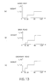
- the characteristic of the weight function W is such that it exhibits different values for different road types (e.g., speedway, main road, and ordinary road) in accordance with the direction difference ⁇ (the difference between the vehicle travel direction and the node connecting direction D C ) which is represented by equation (4).
- the weight W varies in accordance with this direction difference ⁇ .
- Fig. 15 shows the general characteristic of the weight W which increases in such a manner that, the larger the direction difference ⁇ , the larger the value of the evaluation function T.
- the weight W is relatively large in the case of a road which is of less significance as compared in the case of more significant type of roads. The reason for this arrangement is as follows:
- the vehicle is traveling on a speedway.
- the vehicle will not be deviated from the road to a large degree except when entering interchanges or service areas.
- the criterion may be less rigid, and even those nodes which are not likely to be the target can be "positively" included ("map matched) in the candidates. From this point of view, it is arranged such that, the more straight the road, the smaller the value of the weight function W, as shown in Fig. 13, so that the direction difference ⁇ may have as little influence as possible on the evaluation function T.
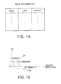
- the weight function W is stored in the memory 13 in the manner shown in Fig. 14 along with the node information, etc.
- the type of weight function W is selected from among (a) to (c) of Fig. 13 in accordance with the type of the road to which the node N L reached by the vehicle as the last one.
- the threshold K may be varied in accordance with the road types. It is arranged such that, the more straight the road, the larger the threshold K, thereby lowering the possibility of nodes thereon being excluded from the candidates.
- the frequency with which map matching is conducted may be varied in accordance with the road types. In other words, it may be arranged such that, the more straight the road, the less the frequency with which map matching is conducted. If map matching is conducted less frequently, the errors in the dead-reckoning increases. However, in the case of a road which exhibits a high degree of straightness, those nodes which would be excluded from the candidates in the usual control due to the increased errors can be retained as candidates and be map-matched "forcibly" to some degree.
Landscapes
- Engineering & Computer Science (AREA)
- Radar, Positioning & Navigation (AREA)
- Remote Sensing (AREA)
- Automation & Control Theory (AREA)
- Physics & Mathematics (AREA)
- General Physics & Mathematics (AREA)
- Navigation (AREA)
Applications Claiming Priority (2)
| Application Number | Priority Date | Filing Date | Title |
|---|---|---|---|
| JP63166026A JPH07119617B2 (ja) | 1988-07-05 | 1988-07-05 | 車両用ナビゲーシヨン装置 |
| JP166026/88 | 1988-07-05 |
Publications (3)
| Publication Number | Publication Date |
|---|---|
| EP0349977A2 true EP0349977A2 (de) | 1990-01-10 |
| EP0349977A3 EP0349977A3 (en) | 1990-05-23 |
| EP0349977B1 EP0349977B1 (de) | 1993-01-20 |
Family
ID=15823561
Family Applications (1)
| Application Number | Title | Priority Date | Filing Date |
|---|---|---|---|
| EP89112192A Expired - Lifetime EP0349977B1 (de) | 1988-07-05 | 1989-07-04 | Vorrichtung zur Navigation eines Fahrzeuges |
Country Status (4)
| Country | Link |
|---|---|
| US (1) | US5046011A (de) |
| EP (1) | EP0349977B1 (de) |
| JP (1) | JPH07119617B2 (de) |
| DE (1) | DE68904484T2 (de) |
Cited By (2)
| Publication number | Priority date | Publication date | Assignee | Title |
|---|---|---|---|---|
| WO2002008694A1 (de) * | 2000-07-21 | 2002-01-31 | Siemens Aktiengesellschaft | Navigationsgerät und verfahren zur positionskorrektur |
| DE4230299B4 (de) * | 1992-09-10 | 2005-12-22 | Robert Bosch Gmbh | Verfahren zur Ortung eines Landfahrzeuges |
Families Citing this family (105)
| Publication number | Priority date | Publication date | Assignee | Title |
|---|---|---|---|---|
| US5646856A (en) * | 1989-06-08 | 1997-07-08 | Kaesser; Juergen | Vehicle navigation system |
| DE4009355A1 (de) * | 1990-03-23 | 1991-09-26 | Teves Gmbh Alfred | Schaltungsanordnung fuer ein kraftfahrzeug mit blockierschutz- und/oder antriebsschlupfregelung |
| NL9001810A (nl) * | 1990-08-13 | 1992-03-02 | Philips Nv | Werkwijze voor de positiebepaling van een voertuig, inrichting voor de positiebepaling van een voertuig, alsmede voertuig voorzien van de inrichting. |
| EP0485132B1 (de) * | 1990-11-06 | 1996-03-06 | Fujitsu Ten Limited | Richtungssensor mit einem Erdmagnetismussensor und einem Drehgeschwindigkeitskreiselsensor und Navigationssystem, welches diesen Richtungssensor enthält |
| US5416477A (en) * | 1990-11-06 | 1995-05-16 | Matsushita Electric Industrial Co., Ltd. | Navigation system mounted on vehicle |
| JP2657581B2 (ja) * | 1990-11-28 | 1997-09-24 | 本田技研工業株式会社 | 移動体の現在位置表示装置 |
| JPH04249714A (ja) * | 1990-12-26 | 1992-09-04 | Clarion Co Ltd | 車載用ナビゲーション装置 |
| EP0514887B1 (de) * | 1991-05-21 | 1997-04-16 | Matsushita Electric Industrial Co., Ltd. | Fahrzeugpositionsbestimmungsvorrichtung |
| JPH0618274A (ja) * | 1991-05-22 | 1994-01-25 | Nec Home Electron Ltd | 車載用航法装置 |
| DE69232261T2 (de) * | 1991-11-01 | 2002-07-25 | Motorola, Inc. | Sensorsystem mit verbesserter genauigkeit zur fahrzeugnavigation |
| JPH05158405A (ja) * | 1991-12-11 | 1993-06-25 | Hitachi Ltd | 経路入力装置 |
| US5394333A (en) * | 1991-12-23 | 1995-02-28 | Zexel Usa Corp. | Correcting GPS position in a hybrid naviation system |
| US8352400B2 (en) | 1991-12-23 | 2013-01-08 | Hoffberg Steven M | Adaptive pattern recognition based controller apparatus and method and human-factored interface therefore |
| US10361802B1 (en) | 1999-02-01 | 2019-07-23 | Blanding Hovenweep, Llc | Adaptive pattern recognition based control system and method |
| JPH05312579A (ja) * | 1992-05-08 | 1993-11-22 | Murata Mfg Co Ltd | ジャイロコンパス |
| US5359529A (en) * | 1992-05-15 | 1994-10-25 | Zexel Corporation | Route guidance on/off-route state filter |
| US5758313A (en) * | 1992-10-16 | 1998-05-26 | Mobile Information Systems, Inc. | Method and apparatus for tracking vehicle location |
| US5428546A (en) * | 1992-10-16 | 1995-06-27 | Mobile Information Systems | Method and apparatus for tracking vehicle location |
| JPH06180235A (ja) * | 1992-12-14 | 1994-06-28 | Pioneer Electron Corp | ナビゲーション装置 |
| US5374933A (en) * | 1993-01-05 | 1994-12-20 | Zexel Corporation | Position correction method for vehicle navigation system |
| US5661650A (en) * | 1994-02-23 | 1997-08-26 | Honda Giken Kogyo Kabushiki Kaisha | System for controlling a vehicle relative to a judged shape of a travel road |
| US5512904A (en) * | 1994-06-13 | 1996-04-30 | Andrew Corporation | Method and apparatus of establishing a vehicle azimuth |
| US5477470A (en) * | 1994-06-20 | 1995-12-19 | Lewis; W. Stan | Real-time digital orientation device |
| US5515283A (en) * | 1994-06-20 | 1996-05-07 | Zexel Corporation | Method for identifying highway access ramps for route calculation in a vehicle navigation system |
| US5517430A (en) * | 1994-06-20 | 1996-05-14 | Directional Robotics Research, Inc. | Real-time digital orientation device |
| US5938720A (en) * | 1995-02-09 | 1999-08-17 | Visteon Technologies, Llc | Route generation in a vehicle navigation system |
| US5712788A (en) * | 1995-02-09 | 1998-01-27 | Zexel Corporation | Incremental route calculation |
| US5904727A (en) * | 1995-05-17 | 1999-05-18 | Mobile Information Systems, Inc. | Graphical fleet management methods |
| US5922040A (en) * | 1995-05-17 | 1999-07-13 | Mobile Information System, Inc. | Method and apparatus for fleet management |
| US5731978A (en) * | 1995-06-07 | 1998-03-24 | Zexel Corporation | Method and apparatus for enhancing vehicle navigation through recognition of geographical region types |
| US5680312A (en) * | 1995-06-07 | 1997-10-21 | Zexel Corporation | Method and apparatus for selecting a destination in a vehicle navigation system |
| JP3545839B2 (ja) * | 1995-06-09 | 2004-07-21 | 株式会社ザナヴィ・インフォマティクス | 現在位置算出装置 |
| US5902351A (en) * | 1995-08-24 | 1999-05-11 | The Penn State Research Foundation | Apparatus and method for tracking a vehicle |
| US5774824A (en) * | 1995-08-24 | 1998-06-30 | The Penn State Research Foundation | Map-matching navigation system |
| US5898390A (en) * | 1995-09-14 | 1999-04-27 | Zexel Corporation | Method and apparatus for calibration of a distance sensor in a vehicle navigation system |
| US5991692A (en) * | 1995-12-28 | 1999-11-23 | Magellan Dis, Inc. | Zero motion detection system for improved vehicle navigation system |
| US5862511A (en) * | 1995-12-28 | 1999-01-19 | Magellan Dis, Inc. | Vehicle navigation system and method |
| US6029111A (en) * | 1995-12-28 | 2000-02-22 | Magellan Dis, Inc. | Vehicle navigation system and method using GPS velocities |
| US5987375A (en) * | 1996-02-14 | 1999-11-16 | Visteon Technologies, Llc | Method and apparatus for selecting a destination in a vehicle navigation system |
| US5819200A (en) * | 1996-02-14 | 1998-10-06 | Zexel Corporation | Method and apparatus for selecting a destination in a vehicle navigation system |
| US6029110A (en) * | 1996-09-30 | 2000-02-22 | Visteon Technologies, Llc | Method and apparatus for providing passenger access to a vehicle navigation system |
| US5904728A (en) * | 1996-10-11 | 1999-05-18 | Visteon Technologies, Llc | Voice guidance timing in a vehicle navigation system |
| US5902350A (en) * | 1996-10-30 | 1999-05-11 | Visteon Technologies, Llc | Generating a maneuver at the intersection through a turn lane |
| US6253154B1 (en) | 1996-11-22 | 2001-06-26 | Visteon Technologies, Llc | Method and apparatus for navigating with correction of angular speed using azimuth detection sensor |
| US5910177A (en) * | 1996-12-09 | 1999-06-08 | Visteon Technologies, Llc | Navigating close proximity routes with a vehicle navigation system |
| US6308134B1 (en) | 1996-12-27 | 2001-10-23 | Magellan Dis, Inc. | Vehicle navigation system and method using multiple axes accelerometer |
| US5928307A (en) * | 1997-01-15 | 1999-07-27 | Visteon Technologies, Llc | Method and apparatus for determining an alternate route in a vehicle navigation system |
| US6324592B1 (en) | 1997-02-25 | 2001-11-27 | Keystone Aerospace | Apparatus and method for a mobile computer architecture and input/output management system |
| US6889139B2 (en) * | 1997-03-07 | 2005-05-03 | Sidewinder Holdings Ltd. | System and method for mobile data processing and transmission |
| JP3466413B2 (ja) * | 1997-04-04 | 2003-11-10 | トヨタ自動車株式会社 | 経路探索装置 |
| US6212472B1 (en) | 1997-09-04 | 2001-04-03 | Visteon Technologies, Llc | Method and apparatus for displaying current vehicle position |
| US6047234A (en) * | 1997-10-16 | 2000-04-04 | Navigation Technologies Corporation | System and method for updating, enhancing or refining a geographic database using feedback |
| US7268700B1 (en) | 1998-01-27 | 2007-09-11 | Hoffberg Steven M | Mobile communication device |
| US6144919A (en) | 1998-03-27 | 2000-11-07 | Visteon Technologies, Llc | Method and apparatus for using non-digitized cities for route calculation |
| US6108603A (en) * | 1998-04-07 | 2000-08-22 | Magellan Dis, Inc. | Navigation system using position network for map matching |
| US6097316A (en) * | 1998-04-20 | 2000-08-01 | Visteon Technologies, Llc | Communication protocol for a vehicle navigation system |
| US6298305B1 (en) | 1998-07-15 | 2001-10-02 | Visteon Technologies, Llc | Methods and apparatus for providing voice guidance in a vehicle navigation system |
| US6088649A (en) * | 1998-08-05 | 2000-07-11 | Visteon Technologies, Llc | Methods and apparatus for selecting a destination in a vehicle navigation system |
| US7966078B2 (en) | 1999-02-01 | 2011-06-21 | Steven Hoffberg | Network media appliance system and method |
| US20040215387A1 (en) * | 2002-02-14 | 2004-10-28 | Matsushita Electric Industrial Co., Ltd. | Method for transmitting location information on a digital map, apparatus for implementing the method, and traffic information provision/reception system |
| JP3481168B2 (ja) * | 1999-08-27 | 2003-12-22 | 松下電器産業株式会社 | デジタル地図の位置情報伝達方法 |
| US6360165B1 (en) | 1999-10-21 | 2002-03-19 | Visteon Technologies, Llc | Method and apparatus for improving dead reckoning distance calculation in vehicle navigation system |
| US6282496B1 (en) | 1999-10-29 | 2001-08-28 | Visteon Technologies, Llc | Method and apparatus for inertial guidance for an automobile navigation system |
| US6654682B2 (en) * | 2000-03-23 | 2003-11-25 | Siemens Transportation Systems, Inc. | Transit planning system |
| US6456935B1 (en) | 2000-03-28 | 2002-09-24 | Horizon Navigation, Inc. | Voice guidance intonation in a vehicle navigation system |
| US6456234B1 (en) | 2000-06-07 | 2002-09-24 | William J. Johnson | System and method for proactive content delivery by situation location |
| US8060389B2 (en) | 2000-06-07 | 2011-11-15 | Apple Inc. | System and method for anonymous location based services |
| US8073565B2 (en) | 2000-06-07 | 2011-12-06 | Apple Inc. | System and method for alerting a first mobile data processing system nearby a second mobile data processing system |
| US6735516B1 (en) | 2000-09-06 | 2004-05-11 | Horizon Navigation, Inc. | Methods and apparatus for telephoning a destination in vehicle navigation |
| JP5041638B2 (ja) * | 2000-12-08 | 2012-10-03 | パナソニック株式会社 | デジタル地図の位置情報伝達方法とそれに使用する装置 |
| JP4663136B2 (ja) | 2001-01-29 | 2011-03-30 | パナソニック株式会社 | デジタル地図の位置情報伝達方法と装置 |
| JP4749594B2 (ja) | 2001-04-27 | 2011-08-17 | パナソニック株式会社 | デジタル地図の位置情報伝達方法 |
| JP4230132B2 (ja) * | 2001-05-01 | 2009-02-25 | パナソニック株式会社 | デジタル地図の形状ベクトルの符号化方法と位置情報伝達方法とそれを実施する装置 |
| US6973318B2 (en) * | 2001-11-26 | 2005-12-06 | Motorola, Inc. | Apparatus and method for downloading journey-related information |
| US9818136B1 (en) | 2003-02-05 | 2017-11-14 | Steven M. Hoffberg | System and method for determining contingent relevance |
| US20060080036A1 (en) * | 2004-10-07 | 2006-04-13 | General Motors Corporation | Method for determining vehicle location |
| US7353034B2 (en) | 2005-04-04 | 2008-04-01 | X One, Inc. | Location sharing and tracking using mobile phones or other wireless devices |
| JP2007033434A (ja) * | 2005-06-20 | 2007-02-08 | Denso Corp | 車両用現在位置検出装置、及び車両制御装置 |
| US8745041B1 (en) * | 2006-12-12 | 2014-06-03 | Google Inc. | Ranking of geographic information |
| US8774825B2 (en) | 2007-06-28 | 2014-07-08 | Apple Inc. | Integration of map services with user applications in a mobile device |
| US8108144B2 (en) | 2007-06-28 | 2012-01-31 | Apple Inc. | Location based tracking |
| US8762056B2 (en) | 2007-06-28 | 2014-06-24 | Apple Inc. | Route reference |
| US8275352B2 (en) | 2007-06-28 | 2012-09-25 | Apple Inc. | Location-based emergency information |
| US8332402B2 (en) | 2007-06-28 | 2012-12-11 | Apple Inc. | Location based media items |
| US8311526B2 (en) | 2007-06-28 | 2012-11-13 | Apple Inc. | Location-based categorical information services |
| US8385946B2 (en) | 2007-06-28 | 2013-02-26 | Apple Inc. | Disfavored route progressions or locations |
| US8175802B2 (en) | 2007-06-28 | 2012-05-08 | Apple Inc. | Adaptive route guidance based on preferences |
| US8204684B2 (en) * | 2007-06-28 | 2012-06-19 | Apple Inc. | Adaptive mobile device navigation |
| US8180379B2 (en) | 2007-06-28 | 2012-05-15 | Apple Inc. | Synchronizing mobile and vehicle devices |
| US8290513B2 (en) | 2007-06-28 | 2012-10-16 | Apple Inc. | Location-based services |
| US9109904B2 (en) | 2007-06-28 | 2015-08-18 | Apple Inc. | Integration of map services and user applications in a mobile device |
| US9066199B2 (en) | 2007-06-28 | 2015-06-23 | Apple Inc. | Location-aware mobile device |
| US8554475B2 (en) * | 2007-10-01 | 2013-10-08 | Mitac International Corporation | Static and dynamic contours |
| US8355862B2 (en) | 2008-01-06 | 2013-01-15 | Apple Inc. | Graphical user interface for presenting location information |
| US9250092B2 (en) | 2008-05-12 | 2016-02-02 | Apple Inc. | Map service with network-based query for search |
| US8644843B2 (en) | 2008-05-16 | 2014-02-04 | Apple Inc. | Location determination |
| US8369867B2 (en) | 2008-06-30 | 2013-02-05 | Apple Inc. | Location sharing |
| US8359643B2 (en) | 2008-09-18 | 2013-01-22 | Apple Inc. | Group formation using anonymous broadcast information |
| US8260320B2 (en) | 2008-11-13 | 2012-09-04 | Apple Inc. | Location specific content |
| US8666367B2 (en) | 2009-05-01 | 2014-03-04 | Apple Inc. | Remotely locating and commanding a mobile device |
| US8670748B2 (en) | 2009-05-01 | 2014-03-11 | Apple Inc. | Remotely locating and commanding a mobile device |
| US8660530B2 (en) | 2009-05-01 | 2014-02-25 | Apple Inc. | Remotely receiving and communicating commands to a mobile device for execution by the mobile device |
| CN111380545B (zh) * | 2015-02-10 | 2024-11-12 | 御眼视觉技术有限公司 | 用于自主车辆导航的方法、服务器、自主车辆以及介质 |
| US11525688B2 (en) * | 2017-12-15 | 2022-12-13 | Samsung Electronics Co., Ltd. | Method and apparatus for determining object position |
| US12196557B2 (en) * | 2020-06-17 | 2025-01-14 | Novatel Inc. | System and method for dead reckoning for marine positioning applications |
Family Cites Families (7)
| Publication number | Priority date | Publication date | Assignee | Title |
|---|---|---|---|---|
| US4890104A (en) * | 1983-03-25 | 1989-12-26 | Nippondenso Co., Ltd. | Electronic map display system for use on vehicle |
| JPS60229799A (ja) * | 1984-04-27 | 1985-11-15 | 三菱電機株式会社 | 車載用ナビゲ−タ |
| US4796191A (en) * | 1984-06-07 | 1989-01-03 | Etak, Inc. | Vehicle navigational system and method |
| JPH0643899B2 (ja) * | 1985-03-20 | 1994-06-08 | 日産自動車株式会社 | 車両用経路誘導装置 |
| CA1254628A (en) * | 1985-04-19 | 1989-05-23 | Akira Iihoshi | Device for displying travel path of motor vehicle |
| JP2526876B2 (ja) * | 1986-11-17 | 1996-08-21 | 日本電装株式会社 | 車両走行位置表示装置 |
| JPS63150619A (ja) * | 1986-12-15 | 1988-06-23 | Honda Motor Co Ltd | 走行経路表示装置 |
-
1988
- 1988-07-05 JP JP63166026A patent/JPH07119617B2/ja not_active Expired - Fee Related
-
1989
- 1989-06-30 US US07/374,262 patent/US5046011A/en not_active Expired - Lifetime
- 1989-07-04 DE DE8989112192T patent/DE68904484T2/de not_active Expired - Fee Related
- 1989-07-04 EP EP89112192A patent/EP0349977B1/de not_active Expired - Lifetime
Cited By (3)
| Publication number | Priority date | Publication date | Assignee | Title |
|---|---|---|---|---|
| DE4230299B4 (de) * | 1992-09-10 | 2005-12-22 | Robert Bosch Gmbh | Verfahren zur Ortung eines Landfahrzeuges |
| WO2002008694A1 (de) * | 2000-07-21 | 2002-01-31 | Siemens Aktiengesellschaft | Navigationsgerät und verfahren zur positionskorrektur |
| US6816785B2 (en) | 2000-07-21 | 2004-11-09 | Siemens Aktiengesellschaft | Navigation device and position correction method |
Also Published As
| Publication number | Publication date |
|---|---|
| JPH07119617B2 (ja) | 1995-12-20 |
| EP0349977B1 (de) | 1993-01-20 |
| DE68904484D1 (de) | 1993-03-04 |
| EP0349977A3 (en) | 1990-05-23 |
| US5046011A (en) | 1991-09-03 |
| JPH0217407A (ja) | 1990-01-22 |
| DE68904484T2 (de) | 1993-08-05 |
Similar Documents
| Publication | Publication Date | Title |
|---|---|---|
| US5046011A (en) | Apparatus for navigating vehicle | |
| EP0339639B1 (de) | Fahrzeugnavigationseinrichtung | |
| EP0471405B1 (de) | Verfahren zur Ortsbestimmung eines Fahrzeuges, Anordnung zur Ortsbestimmung eines Fahrzeuges sowie Fahrzeug mit der Anordnung | |
| US5774824A (en) | Map-matching navigation system | |
| JP2778374B2 (ja) | 車両用ナビゲーション装置 | |
| EP0166547B1 (de) | Vorrichtung für Fahrzeugnavigation | |
| JP3413087B2 (ja) | 車両ナビゲーションシステムにより近接ルートを案内する方法及び装置 | |
| US5731978A (en) | Method and apparatus for enhancing vehicle navigation through recognition of geographical region types | |
| Blazquez et al. | Simple map-matching algorithm applied to intelligent winter maintenance vehicle data | |
| US20230063809A1 (en) | Method for improving road topology through sequence estimation and anchor point detetection | |
| JP2544855B2 (ja) | 車両誘導装置 | |
| JPH1089979A (ja) | 車載用ナビゲーション装置 | |
| JPH0688732A (ja) | 車両用ナビゲーション装置 | |
| CN118439031A (zh) | 容纳不一致的感知和地图数据的感知与地图边缘关联系统 | |
| JPH0781872B2 (ja) | 位置検出精度判定方法およびその方法を用いた車両誘導装置 | |
| JP2633630B2 (ja) | 車両用ナビゲーシヨン装置 | |
| US20240418534A1 (en) | Drive assist formulation apparatus and drive assist formulation method | |
| JPH06341844A (ja) | 車載用ナビゲーション装置 | |
| JP3509745B2 (ja) | 車両位置算出装置 | |
| JP2005249654A (ja) | ナビゲーション装置 | |
| JP3551473B2 (ja) | 車両走行位置推定装置 | |
| JPH09229698A (ja) | 位置検出装置 | |
| JPH0572970A (ja) | 車両位置検出装置 | |
| JP7811495B2 (ja) | 駐車場種別判定システム | |
| JPH07209005A (ja) | 推奨経路案内装置 |
Legal Events
| Date | Code | Title | Description |
|---|---|---|---|
| PUAI | Public reference made under article 153(3) epc to a published international application that has entered the european phase |
Free format text: ORIGINAL CODE: 0009012 |
|
| AK | Designated contracting states |
Kind code of ref document: A2 Designated state(s): DE FR GB |
|
| PUAL | Search report despatched |
Free format text: ORIGINAL CODE: 0009013 |
|
| AK | Designated contracting states |
Kind code of ref document: A3 Designated state(s): DE FR GB |
|
| 17P | Request for examination filed |
Effective date: 19900710 |
|
| 17Q | First examination report despatched |
Effective date: 19910702 |
|
| GRAA | (expected) grant |
Free format text: ORIGINAL CODE: 0009210 |
|
| AK | Designated contracting states |
Kind code of ref document: B1 Designated state(s): DE FR GB |
|
| REF | Corresponds to: |
Ref document number: 68904484 Country of ref document: DE Date of ref document: 19930304 |
|
| ET | Fr: translation filed | ||
| PLBI | Opposition filed |
Free format text: ORIGINAL CODE: 0009260 |
|
| 26 | Opposition filed |
Opponent name: ROBERT BOSCH GMBH Effective date: 19931006 |
|
| PLBN | Opposition rejected |
Free format text: ORIGINAL CODE: 0009273 |
|
| STAA | Information on the status of an ep patent application or granted ep patent |
Free format text: STATUS: OPPOSITION REJECTED |
|
| 27O | Opposition rejected |
Effective date: 19950208 |
|
| REG | Reference to a national code |
Ref country code: GB Ref legal event code: IF02 |
|
| PGFP | Annual fee paid to national office [announced via postgrant information from national office to epo] |
Ref country code: GB Payment date: 20030702 Year of fee payment: 15 |
|
| PGFP | Annual fee paid to national office [announced via postgrant information from national office to epo] |
Ref country code: FR Payment date: 20030711 Year of fee payment: 15 |
|
| PG25 | Lapsed in a contracting state [announced via postgrant information from national office to epo] |
Ref country code: GB Free format text: LAPSE BECAUSE OF NON-PAYMENT OF DUE FEES Effective date: 20040704 |
|
| GBPC | Gb: european patent ceased through non-payment of renewal fee |
Effective date: 20040704 |
|
| PG25 | Lapsed in a contracting state [announced via postgrant information from national office to epo] |
Ref country code: FR Free format text: LAPSE BECAUSE OF NON-PAYMENT OF DUE FEES Effective date: 20050331 |
|
| REG | Reference to a national code |
Ref country code: FR Ref legal event code: ST |
|
| PGFP | Annual fee paid to national office [announced via postgrant information from national office to epo] |
Ref country code: DE Payment date: 20060629 Year of fee payment: 18 |
|
| PG25 | Lapsed in a contracting state [announced via postgrant information from national office to epo] |
Ref country code: DE Free format text: LAPSE BECAUSE OF NON-PAYMENT OF DUE FEES Effective date: 20080201 |