EP0350050A2 - Vorschubgrössendetektor für Einzelblatt - Google Patents
Vorschubgrössendetektor für Einzelblatt Download PDFInfo
- Publication number
- EP0350050A2 EP0350050A2 EP89112396A EP89112396A EP0350050A2 EP 0350050 A2 EP0350050 A2 EP 0350050A2 EP 89112396 A EP89112396 A EP 89112396A EP 89112396 A EP89112396 A EP 89112396A EP 0350050 A2 EP0350050 A2 EP 0350050A2
- Authority
- EP
- European Patent Office
- Prior art keywords
- sheet member
- feeding
- feed
- amount
- image
- Prior art date
- Legal status (The legal status is an assumption and is not a legal conclusion. Google has not performed a legal analysis and makes no representation as to the accuracy of the status listed.)
- Granted
Links
Images


Classifications
-
- B—PERFORMING OPERATIONS; TRANSPORTING
- B41—PRINTING; LINING MACHINES; TYPEWRITERS; STAMPS
- B41J—TYPEWRITERS; SELECTIVE PRINTING MECHANISMS, i.e. MECHANISMS PRINTING OTHERWISE THAN FROM A FORME; CORRECTION OF TYPOGRAPHICAL ERRORS
- B41J11/00—Devices or arrangements of selective printing mechanisms, e.g. ink-jet printers or thermal printers, for supporting or handling copy material in sheet or web form
- B41J11/36—Blanking or long feeds; Feeding to a particular line, e.g. by rotation of platen or feed roller
- B41J11/42—Controlling printing material conveyance for accurate alignment of the printing material with the printhead; Print registering
- B41J11/44—Controlling printing material conveyance for accurate alignment of the printing material with the printhead; Print registering by devices, e.g. program tape or contact wheel, moved in correspondence with movement of paper-feeding devices, e.g. platen rotation
-
- B—PERFORMING OPERATIONS; TRANSPORTING
- B41—PRINTING; LINING MACHINES; TYPEWRITERS; STAMPS
- B41J—TYPEWRITERS; SELECTIVE PRINTING MECHANISMS, i.e. MECHANISMS PRINTING OTHERWISE THAN FROM A FORME; CORRECTION OF TYPOGRAPHICAL ERRORS
- B41J11/00—Devices or arrangements of selective printing mechanisms, e.g. ink-jet printers or thermal printers, for supporting or handling copy material in sheet or web form
- B41J11/36—Blanking or long feeds; Feeding to a particular line, e.g. by rotation of platen or feed roller
- B41J11/42—Controlling printing material conveyance for accurate alignment of the printing material with the printhead; Print registering
Definitions
- the present invention relates to an apparatus for detecting an amount of feed of a sheet member, which can control a sheet feeding means by detecting the amount of feed of the sheet member.
- an image was recorded on a recording sheet (to be fed) per a predetermined printing width (per one line) by means of a recording head, and the recording sheet was fed by a predetermined amount (corresponding to the printing width) to effect a line space whenever each line was printed; in this way, the printing operations were repeated to obtain the whole image.
- the accuracy of the amount of feed of the recording sheet differs in dependence upon resolving power of the character, since the resolving power of the character is normally in the order of 200 dot/inch - 400 dot/inch, the accuracy of the amount of feed of the recording sheet was required to have a value of 60 - 30 ⁇ m.
- the diameter and rotational amount of a feed roller were previously calculated in correspondence to the amount of feed of the recording sheet (to be fed by the feeding roller), and the recording sheet was fed by controlling a driving time of a feed motor for driving the feed roller by means of a CPU.
- an apparatus for detecting an amount of feed of a sheet member which comprises a feeding means for feeding the sheet member, and a detecting means for detecting the amount of feed of the sheet member by using a rotary member rotatingly driven by engaging with the sheet member fed by the feeding means and for controlling the feeding means.
- the feeding means can be controlled by directly detecting the amount of feed of the sheet member fed by the feeding means by means of the detecting means, the sheet member can be positively fed by a predetermined amount with accuracy, thereby maintaining the recorded image with high quality.
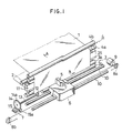
- Fig. 1 shows a schematic explanatory view of an ink jet recording apparatus
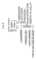
- Fig. 2 shows a control block diagram therefor.
- recording sheets 1 each comprising a sheet member such as a paper, plastic sheet or the like are stacked in a cassette (not shown) and are supplied one by one by means of a supplying roller 2 driven by a supplying motor to a feeding means which will be described later, through an appropriate guide member (not shown).
- the recording sheet 1 is pinched by a pair 3 of feed rollers and a pair 4 of ejector or discharge rollers, which roller pairs are spaced apart by a predetermined distance and are driven intermittently by respective feed motor (not shown) respectively, and is fed in a direction shown by the arrow A.
- the roller pair 3 is used for pinching (or gripping) and feeding the recording sheet 1 toward a recording portion which will be described later, and comprises a feed roller 3a and a follower roller 3b which are engaged by each other with the interposition of the recording sheet 1.
- the feed roller 3a is designed to be rotated by an appropriate driving source (not shown) in a direction shown by the arrow C.
- the roller pair 4 is used for gripping the recording sheet 1 on which the image has been recorded and which is being fed by the roller pair 3, to eject or discharge the recording sheet out of the recording apparatus, and comprises an ejector or discharge roller 4a and a follower roller 4b which are engaged by each other with the interposition of the recording sheet 1.
- the ejector roller 4a is designed to be rotated by an appropriate driving source (not shown) in a direction shown by the arrow C.
- the ejector roller 4a is rotated slightly faster than the feed roller 3a so that the recording sheet 1 does not slacken or loosen in the recording portion. Further, the feed roller 3a in the roller pair 3 has a width same as or wider than that of the recording sheet 1, whereas the follower roller 3b has a width narrower than that of the recording sheet so that a detecting roller or wheel (to be described later) can abut against the feed roller 3a with the interposition of the recording sheet 1 at one side of the follower roller 3b.
- An ink jet recording head 5 arranged in the recording portion and used for recording the image on the recording sheet 1 has an ink chamber therein and is designed to discharge the ink from a nozzle in response to an image signal.
- the recording head 5 is mounted on a carriage 6 which is connected to a carriage motor 9 through a belt 7 and pulleys 8a, 8b. Accordingly, by driving the carriage motor 9, the carriage 6 is reciprocally shifted along guide shafts 10.
- a heating plate 11 having a heater therein is arranged on a back side of the recording wheet 1 between the feed roller pair 3 and the ejector roller pair 4.
- the heating plate 11 applies the heat to the back of the recording sheet 1 being fed, thereby drying the ink applied on the surface of the recording sheet 1 to fix the ink on the recording sheet.
- the recording head 5 when the recording operation is started, the recording head 5 is shifted in a direction shown by the arrow B, during which the head 5 discharges the ink on the recording sheet 1 in response to the image signal, thereby recording an ink image on the recording sheet.
- the recording head 5 After one line recording operation is completed, the recording head 5 returns to its home position, and the feed roller pair 3 and the ejector roller pair 4 are driven to feed the recording sheet 1 in the direction shown by the arrow A by a predetermined amount, i.e., by a distance corresponding to a width of one line. By repeating such recording operations, a desired image is recorded on the recording sheet 1.
- the detecting wheel 12 used as a rotary member for detecting the amount of feed of the recording sheet 1 is arranged in alignment with the follower roller 3b to engage by the recording sheet 1 on the feed roller 3a, and is rotatingly driven by the movement of the recording sheet 1.
- the detecting wheel 12 is connected at center thereof to a rotatable shaft 13, on the other end of which a disc-shaped encoder 14 is fixed.
- the encoder 14 is provided at its peripheral portion with a plurality of equidistantly spaced slits 14a and is rotated in response to the rotation of the detecting wheel 12. Further, the peripheral portion of the encoder 14 in which the slits 14a are formed passes through a recess or cavity 15a of a photo-interrupter 15.
- the photo-interrupter 15 emits a pulse signal whenever the slit 14a passes therethrough, whereby a control portion (described later) counts the number of such pulses, thus detecting the amount of feed of the recording sheet.
- the control system comprises the aforementioned control portion 16 including a CPU 16a such as a microprocessor, a ROM 16b for storing a control program for the CPU 16a and other various data, and a RAM 16c used as a work area for the CPU 16a and used for temporally storing the various data; an inter face 17; an operating panel 18; a motor driver 21 for driving various motors (carriage motor 9, supply motor 19, feed motor 20); a head driver 22 for driving the recording head 5; a heater 23 for the heating plate 11; a recording sheet detecting sensor 25; and the aforementioned photo-interrupter 15 .
- a CPU 16a such as a microprocessor
- ROM 16b for storing a control program for the CPU 16a and other various data
- RAM 16c used as a work area for the CPU 16a and used for temporally storing the various data
- an inter face 17 an operating panel 18
- a motor driver 21 for driving various motors (carriage motor 9, supply motor 19, feed motor
- the control portion 16 receives various informations (for example, density of image to be recorded, the number of sheets to be recorded, size of sheet to be recorded and the like) from the operating panel 18 and the pulse signals (regarding the slits 14a) from the photo-interrupter 15 through the interface 17, and further receives the image signal from an outer device 24. Further, the control portion 16 outputs ON/OFF signals for controlling the various motors, an ON/OFF signal for controlling the heating plate heater 23, and an image signal through the interface 17, whereby various members or elements are driven by such signals. Further, the recording sheet detecting sensor 25 detects a leading edge and a trailing edge of the recording sheet 1 fed between the feed roller pair 3 and the ejector roller pair 4, thereby controlling the motors for driving the roller pairs.
- various informations for example, density of image to be recorded, the number of sheets to be recorded, size of sheet to be recorded and the like
- the control portion 16 outputs ON/OFF signals for controlling the various motors, an ON/OFF signal for controlling the heating plate heater 23, and an image signal
- Fig. 3 when an operating signal is inputted, the heater 23 is turned ON to heat the heating plate 11 up to a predetermined temperature in a condition that the recording sheet does not reach the heating plate 11, and after the predetermined temperature is reached, the supply motor 19 and the feed motor 20 are driven to rotate the supplying roller 2, feed roller pair 3 and ejector roller pair 4, thereby feeding the recording sheet 1 between the feed roller pair 3 and the ejector roller pair 4 (step S1).
- step S2 - S4 the leading edge of the recording sheet 1 fed between the feed roller pair 3 and the ejector roller pair 4 is detected by the detecting sensor 25 (the details thereof are not shown), and after the recording sheet 1 is fed by the predetermined amount, the feeding operation of the recording sheet by means of the various motors is temporally stopped (steps S2 - S4).
- the recording operation is started, during which the carriage 6 is shifted in the direction shown by the arrow B in Fig. 1 and the recording head 5 discharges the ink onto the recording sheet 1 in response to the image signal, thus recording the ink image corresponding to one line on the recording sheet 1.
- the carriage 6 is returned to the home position and the recording sheet 1 is fed in the direction shown by the arrow A in Fig. 1 by a predetermined amount, i.e., by a distance corresponding to a width of one line (steps S5 and S6).
- the detecting wheel 12 contacted with the recording sheet 1 is rotated in response to the feeding movement of the recording sheet 1. Accordingly, the encoder 14 connected to the detecting wheel 12 through the rotatable shaft 13 is also rotatingly driven, with the result that several slits 14a formed in the peripheral portion of the encoder 14 pass through the cavity 15a of the photo-interrupter 15, thus emitting the pulses (the number thereof corresponds to the number of slits passed through the cavity), which is counted in the control portion 16, thereby detecting the amount of feed of the recording sheet 1 (step S7). Accordingly, when the outer diameter of the detecting wheel 12 and the distance between two adjacent slits 14a are previously set or selected correctly, the amount of feed of the recording sheet 1 can be correctly determined by the rotational amount of the encoder 15.
- the sequence returns to the step S4, where, by controlling to stop the feed roller 3a, the recording operation and the feeding operation for the recording sheet 1 are repeated.
- the ejector roller 4a is driven to eject or discharge the recording sheet 1 to an ejector tray (not shown), and the heater 23 is turned OFF to finish the operation (steps S8 and S9).
- the predetermined amount of feed of the recording sheet corresponds to the one line of the image
- such predetermined amount may correspond to two lines or a half of one line of the image, according to the dimension of the image.
- the present invention may be adapted to other recording apparatuses such as a wire dot recording apparatus.
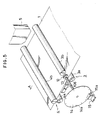
- recording sheets or sheet members 1 such as a plain paper, plastic sheet and the like are stacked in a cassette 101.
- the sheet members 1 in the cassette 101 are supplied one by one by a semi-cylindrical pick-up roller 2 (constituting a supplying means) rotated in response to a supply signal.
- the fed sheet member 1 is guided by upper and lower guides 104, 105 and is directed to a nip between a feed roller pair 3 temporally stopped.
- a feed roller 3a in the feed roller pair 3 is rotatingly driven by a driving means 20a (the details thereof are not shown), and a feed roller 3b in the roller pair 3 is pressed against the feed roller 3a to form the nip therebetween and is rotatingly driven by the feed roller 3a, thus feeding the sheet member 1 steppingly toward a platen 108.
- a recording head 5 arranged in confronting relation to the platen 108 has an ink jet nozzle capable of discharging the ink in response to an image signal, and an ink chamber communicated with the nozzle.
- the recording head 5 is mounted on a carriage 6 which can be reciprocally shifted along guide shafts 10, 11 parallel to the platen 108 in a direction perpendicular to a longitudinal direction of the sheet member 1, thereby performing the recording per one line.
- the carriage 6 is driven by a carriage motor connected to the carriage through a timing belt (not shown) would around pulleys (not shown).
- a feeding speed of the sheet member 1 due to the feed roller pair 3 is previously determined in accordance with the width of 5a of the recording head 5.
- the recording head 5 is shifted from the home position situated this side of Fig. 4 toward the opposite side of Fig. 4 and at the same time selectively discharges the ink in response to the image signal, thereby recording one line of the image.
- the recording head 5 returns to the home position and the sheet member 1 is fed by the predetermined amount, and then a next one line recording is started. By repeating such recording operations, a desired image is formed on the sheet member.
- the sheet member 1 is fed by the ejector roller pair 4 to be ejected onto an ejector tray 115.
- FIG. 6 A block diagram (for controlling the apparatus of Fig. 4) shown in Fig. 6 has a construction similar to that of Fig. 2, and, accordingly, the detailed explanation thereof will be omitted.
- step S11 When the control portion 16 receives a supply signal from the outer device 24 such as a computer, word processor and the like, or from the operating panel 18 (step S11), the supply motor 19 and the feed motor 20a are turned ON, thus starting the rotations of the pick-up roller 2 and the feed roller 3a (step S12), whereby the sheet member 1 is picked up from the cassette 101 by the pick-up roller 2 and is then fed by the feed roller pair 3.
- step S12 When the leading edge of the sheet member 1 is detected by the recording sheet detecting sensor 25 (step 13), the CPU 16a starts to count the pulses from the photo-interrupter 15 (step S14).
- step S15 When the number of the counted pulses reaches a predetermined value N1, i.e., when the sheet member 1 is fed by a predetermined distance l1 from the position of the recording sheet detecting sensor 25 (step S15), the supply motor 19 and the feed motor 20a are turned OFF, thus stopping the feed of the sheet member 1 (step S16). Then, by controlling the carriage motor 9 and the recording head 5, a first one line recording (printing) is performed (step S17).
- step S18 When the one line recording is finished (step S18), the supply motor 19 and the feed motors 20a, 20b are turned ON (step S19), the pulses from the photo-interrupter 15 are counted (step S20). When the number of the counted pulses reaches a predetermined value N2, i.e., when a portion of the sheet member on which a next line of the character is to be recorded reaches the printing position (recording position) of the recording head 5 (step S21), the supply motor 19 and the feed motors 20a, 20b are turned OFF (step S22).
- N2 i.e., when a portion of the sheet member on which a next line of the character is to be recorded reaches the printing position (recording position) of the recording head 5
- step S24 If the recording operation for one page has already been finished or completed (step S24), the feed motors 20a and 20b are turned ON for a predetermined time, thus ejecting the sheet member 1 onto the ejector tray 115. On the other hand, if the recording operation for one page has not yet been finished in the step S24, the sequence returns to the step S17, thus performing the next one line recording operation. In this way, the recording operations are repeated.
- the present invention is not limited to this embodiment.
- the sheet may be fed by such distance l2.
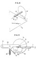
- a diameter of a detecting wheel 12′ is previously set to have a value of a/ ⁇ (here, a is a predetermined value, i.e., a distance corresponding to a width of one line). That is to say, when the recording sheet or sheet member 1 is fed by the predetermined amount a , the detecting wheel 12′ is rotated by one revolution. Further, a disc-shaped encoder 14′ connected to the detecting wheel 12′ through a rotatable shaft 13′ is provided at its peripheral portion with a single slit 14a′.
- the encoder 14′ is rotated by one revolution together with the detecting wheel 12′, whereby the slit 14a′ is detected by a photo-interrupter 15. Accordingly, by controlling to stop the operation of the feed roller 3a when the photo-interrupter 15 detects the slit 14a′, it is possible to positively or correctly feed the recording sheet by the predetermined amount.
- the photo-interrupter 15 since the photo-interrupter 15 detects the single slit 14a′ of the encoder 14′, detection error will be reduced in comparison with the case where a plurality of slits are detected. That is to say, when the encoder has a plurality of slits, the detection error may be occurred due to the mechanical error in the distances between the adjacent slits, whereas, when the encoder has only one slit, the detection error due to such mechanical error does not exist. Further, in the case of the encoder having the plurality of slits, the detection error also arises due to the eccentricity of the encoder and/or detecting wheel which can not inevitably eliminated.
- Fig. 9 shows a supporting means for the detecting wheel 12 (12′) and the encoder 14 (14′) used in the embodiments of Figs. 1 to 8.
- the rotatable shaft 13 of the detecting wheel 12 is rotatably supported by a supporting member 30.
- the supporting member 30 is biased by a spring 32 in a direction shown by the arrow C for pivotal movement around a pivot center 31, so that the detecting wheel 12 is always abutted against the recording sheet 1.
- the surface of the detecting wheel may be constituted by material having high coefficient ( ⁇ ) of friction such as urethane material, in order to prevent the relative slip between the detecting wheel and the recording sheet.
- the detecting wheel composes a metallic body coated by sand blasting technique (abrasive grain is blown onto the metallic surface to obtain a rough surface).
- the recording head 5 may be designed to discharge ink droplets onto the recording sheet by thermal energy, thereby forming the image on the recording sheet.
- the recording head may be constituted by a heat transfer recording head, or a wire dot type recording head.
- the present invention provides a detecting apparatus for detecting an amount of feed of a sheet member.
- Delecting apparatus comprises a feeding means for feeding a sheet member, a rotary member engaged by the sheet member and rotatingly driven by the sheet member being fed by the feeding means, and an calculating circuit for calculating an amount of feed of the sheet member on the basis of a rotational amount of the rotary member.
Landscapes
- Handling Of Sheets (AREA)
- Handling Of Cut Paper (AREA)
- Controlling Sheets Or Webs (AREA)
- Delivering By Means Of Belts And Rollers (AREA)
Applications Claiming Priority (2)
| Application Number | Priority Date | Filing Date | Title |
|---|---|---|---|
| JP1988089494U JPH0213046U (de) | 1988-07-07 | 1988-07-07 | |
| JP89494/88U | 1988-07-07 |
Publications (3)
| Publication Number | Publication Date |
|---|---|
| EP0350050A2 true EP0350050A2 (de) | 1990-01-10 |
| EP0350050A3 EP0350050A3 (en) | 1990-08-22 |
| EP0350050B1 EP0350050B1 (de) | 1995-05-24 |
Family
ID=13972311
Family Applications (1)
| Application Number | Title | Priority Date | Filing Date |
|---|---|---|---|
| EP89112396A Expired - Lifetime EP0350050B1 (de) | 1988-07-07 | 1989-07-06 | Vorschubgrössendetektor für Einzelblatt |
Country Status (4)
| Country | Link |
|---|---|
| US (1) | US5131770A (de) |
| EP (1) | EP0350050B1 (de) |
| JP (1) | JPH0213046U (de) |
| DE (1) | DE68922791T2 (de) |
Cited By (5)
| Publication number | Priority date | Publication date | Assignee | Title |
|---|---|---|---|---|
| EP0584792A3 (en) * | 1992-08-28 | 1994-08-24 | Mitsubishi Electric Corp | Sheet feeding apparatus |
| EP0652111A3 (de) * | 1993-11-05 | 1996-03-06 | Esselte Dymo Nv | Druckerantriebssystem. |
| US5651039A (en) * | 1994-10-28 | 1997-07-22 | Hadewe B.V. | Method for determining the displacement of an object |
| WO2005025880A3 (en) * | 2003-09-05 | 2005-05-19 | Zebra Atlantek Inc | Card cleaning assembly for card printing devices |
| WO2012030694A1 (en) * | 2010-08-30 | 2012-03-08 | Eastman Kodak Company | Encoder for inkjet printers |
Families Citing this family (12)
| Publication number | Priority date | Publication date | Assignee | Title |
|---|---|---|---|---|
| AU649719B2 (en) * | 1990-09-27 | 1994-06-02 | Canon Kabushiki Kaisha | Image recording apparatus utilizing serial recording head and image recording method therefor |
| US5209589A (en) * | 1991-10-25 | 1993-05-11 | Apple Computer, Inc. | Apparatus and method for minimizing printer scan error |
| JP2962948B2 (ja) * | 1992-11-02 | 1999-10-12 | キヤノン株式会社 | 画像形成装置 |
| US5685655A (en) * | 1995-12-12 | 1997-11-11 | Ncr Corporation | Security system for unattended printing mechanism |
| US7344325B2 (en) | 1999-01-25 | 2008-03-18 | Fargo Electronics, Inc. | Identification card printer having ribbon cartridge with cleaner roller |
| JP3684159B2 (ja) * | 2001-01-31 | 2005-08-17 | キヤノン株式会社 | 記録装置および記録方法 |
| US7189018B2 (en) * | 2004-01-28 | 2007-03-13 | Hewlett-Packard Development Company, L.P. | Print media drive |
| TW200636192A (en) * | 2005-03-22 | 2006-10-16 | Miura Kogyo Kk | Damper position adjusting device and combustion apparatus having such damper adjusting device |
| JP4508057B2 (ja) * | 2005-09-22 | 2010-07-21 | コニカミノルタホールディングス株式会社 | 記録装置 |
| JP4211829B2 (ja) * | 2006-09-13 | 2009-01-21 | セイコーエプソン株式会社 | 媒体搬送装置、及び、搬送量の補正方法 |
| JP4345790B2 (ja) * | 2006-09-13 | 2009-10-14 | セイコーエプソン株式会社 | 媒体搬送装置、及び、搬送量の補正方法 |
| JP6112876B2 (ja) * | 2013-01-24 | 2017-04-12 | キヤノン株式会社 | 記録装置 |
Family Cites Families (16)
| Publication number | Priority date | Publication date | Assignee | Title |
|---|---|---|---|---|
| DE2258546C2 (de) * | 1972-11-29 | 1982-10-21 | Siemens AG, 1000 Berlin und 8000 München | Einrichtung zur Papiervorschubüberwachung bei Druckern |
| DE2300421A1 (de) * | 1973-01-05 | 1974-07-11 | Helmut Steinhilber | Steuervorrichtung fuer den vorschub von formularen, belegen und dergl. an bueromaschinen |
| US3917142A (en) * | 1974-04-04 | 1975-11-04 | Data Products Corp | Paper motion sensor apparatus |
| US4027764A (en) * | 1975-06-24 | 1977-06-07 | Casio Computer Co., Ltd. | Apparatus for confirming the correct impression of printing characters |
| GB2046177B (en) * | 1979-03-26 | 1983-04-20 | Seiko Instr & Electronics | Printer |
| JPS59194879A (ja) * | 1983-04-19 | 1984-11-05 | Sanyo Electric Co Ltd | ペ−パ−トツプ自動セツト装置付きプリンタ |
| DE3316580C1 (de) * | 1983-05-06 | 1984-08-16 | Triumph-Adler Aktiengesellschaft für Büro- und Informationstechnik, 8500 Nürnberg | Vorrichtung zur UEberwachung des ordnungsgemaessen Papiereinlaufes in Schreib- und aehnlichen Maschinen |
| JPS60137757A (ja) * | 1983-12-27 | 1985-07-22 | Toshiba Corp | 搬送装置 |
| JPH0611634B2 (ja) * | 1984-07-06 | 1994-02-16 | 日立電子株式会社 | 記録装置の紙送り機構 |
| JPS61144372A (ja) * | 1984-12-19 | 1986-07-02 | Graphtec Corp | 記録装置 |
| JP2522912B2 (ja) * | 1985-10-17 | 1996-08-07 | 三洋電機株式会社 | 熱転写記録装置 |
| JPH07385B2 (ja) * | 1986-03-20 | 1995-01-11 | 株式会社田村電機製作所 | プリンタの用紙排出速度制御装置 |
| JPH085235B2 (ja) * | 1986-10-22 | 1996-01-24 | 富士通株式会社 | 熱転写記録装置 |
| EP0290961B1 (de) * | 1987-05-13 | 1992-04-01 | Seiko Epson Corporation | Papierlängendetektor für einen Drucker |
| GB2215101B (en) * | 1988-02-18 | 1992-04-08 | Unisys Corp | Paper movement monitor |
| US4892426A (en) * | 1988-06-30 | 1990-01-09 | Unisys Corporation | Paper movement monitor |
-
1988
- 1988-07-07 JP JP1988089494U patent/JPH0213046U/ja active Pending
-
1989
- 1989-07-06 DE DE68922791T patent/DE68922791T2/de not_active Expired - Fee Related
- 1989-07-06 US US07/375,980 patent/US5131770A/en not_active Expired - Fee Related
- 1989-07-06 EP EP89112396A patent/EP0350050B1/de not_active Expired - Lifetime
Cited By (10)
| Publication number | Priority date | Publication date | Assignee | Title |
|---|---|---|---|---|
| EP0584792A3 (en) * | 1992-08-28 | 1994-08-24 | Mitsubishi Electric Corp | Sheet feeding apparatus |
| US5555462A (en) * | 1992-08-28 | 1996-09-10 | Mitsubishi Denki Kabushiki Kaisha | Sheet feeding apparatus |
| EP0652111A3 (de) * | 1993-11-05 | 1996-03-06 | Esselte Dymo Nv | Druckerantriebssystem. |
| EP0741044A3 (de) * | 1993-11-05 | 1997-01-08 | Esselte Nv | Druckerantriebssystem |
| US5608443A (en) * | 1993-11-05 | 1997-03-04 | Esselte N.V. | Drive system for a thermal label printer |
| US5651039A (en) * | 1994-10-28 | 1997-07-22 | Hadewe B.V. | Method for determining the displacement of an object |
| WO2005025880A3 (en) * | 2003-09-05 | 2005-05-19 | Zebra Atlantek Inc | Card cleaning assembly for card printing devices |
| US7170537B2 (en) | 2003-09-05 | 2007-01-30 | Zih Corp. | Card-cleaning assembly for card printing devices |
| WO2012030694A1 (en) * | 2010-08-30 | 2012-03-08 | Eastman Kodak Company | Encoder for inkjet printers |
| US8336984B2 (en) | 2010-08-30 | 2012-12-25 | Eastman Kodak Company | Encoder for inkjet printers |
Also Published As
| Publication number | Publication date |
|---|---|
| EP0350050B1 (de) | 1995-05-24 |
| JPH0213046U (de) | 1990-01-26 |
| US5131770A (en) | 1992-07-21 |
| DE68922791T2 (de) | 1995-12-07 |
| DE68922791D1 (de) | 1995-06-29 |
| EP0350050A3 (en) | 1990-08-22 |
Similar Documents
| Publication | Publication Date | Title |
|---|---|---|
| EP0350050B1 (de) | Vorschubgrössendetektor für Einzelblatt | |
| JP3715842B2 (ja) | プリント装置および当該プリント装置におけるプリント媒体の給送方法 | |
| US5910811A (en) | Sheet convey apparatus | |
| US5529414A (en) | Paper feeding apparatus for printer | |
| JP2004123313A (ja) | 被記録材搬送量制御装置、記録装置 | |
| JP2001180057A (ja) | 記録装置 | |
| US5451991A (en) | Recording apparatus | |
| JPH0890776A (ja) | インクジェット記録方法及びインクジェット記録装置 | |
| EP1621358A1 (de) | Drucker | |
| JP2004255752A (ja) | インクジェット記録装置 | |
| EP1719627B1 (de) | Bilderzeugungseinrichtung | |
| JP2000246982A (ja) | インクジェット記録装置及び用紙搬送装置 | |
| JP2884523B2 (ja) | プリンタの媒体排出方法 | |
| JPH07132658A (ja) | インクジェット記録装置 | |
| JPH11188937A (ja) | 印字装置 | |
| JPH01233958A (ja) | 記録装置のシート送り方法 | |
| JP2711851B2 (ja) | 記録装置 | |
| JP2647988B2 (ja) | 記録装置 | |
| JP2882678B2 (ja) | 画像記録装置 | |
| JP2503857B2 (ja) | インクジェット記録装置 | |
| JPH04158078A (ja) | シリアルプリンタ | |
| JPH0747740A (ja) | シリアルプリンタ | |
| JPH09141962A (ja) | プリンタ及びその制御方法 | |
| JPH08282027A (ja) | 記録装置 | |
| JP2003145865A (ja) | 記録装置 |
Legal Events
| Date | Code | Title | Description |
|---|---|---|---|
| PUAI | Public reference made under article 153(3) epc to a published international application that has entered the european phase |
Free format text: ORIGINAL CODE: 0009012 |
|
| AK | Designated contracting states |
Kind code of ref document: A2 Designated state(s): DE FR GB IT |
|
| PUAL | Search report despatched |
Free format text: ORIGINAL CODE: 0009013 |
|
| AK | Designated contracting states |
Kind code of ref document: A3 Designated state(s): DE FR GB IT |
|
| 17P | Request for examination filed |
Effective date: 19901221 |
|
| 17Q | First examination report despatched |
Effective date: 19920810 |
|
| GRAA | (expected) grant |
Free format text: ORIGINAL CODE: 0009210 |
|
| AK | Designated contracting states |
Kind code of ref document: B1 Designated state(s): DE FR GB IT |
|
| REF | Corresponds to: |
Ref document number: 68922791 Country of ref document: DE Date of ref document: 19950629 |
|
| ET | Fr: translation filed | ||
| ITF | It: translation for a ep patent filed | ||
| PLBE | No opposition filed within time limit |
Free format text: ORIGINAL CODE: 0009261 |
|
| STAA | Information on the status of an ep patent application or granted ep patent |
Free format text: STATUS: NO OPPOSITION FILED WITHIN TIME LIMIT |
|
| 26N | No opposition filed | ||
| REG | Reference to a national code |
Ref country code: GB Ref legal event code: IF02 |
|
| PGFP | Annual fee paid to national office [announced via postgrant information from national office to epo] |
Ref country code: GB Payment date: 20030702 Year of fee payment: 15 |
|
| PGFP | Annual fee paid to national office [announced via postgrant information from national office to epo] |
Ref country code: FR Payment date: 20030711 Year of fee payment: 15 |
|
| PGFP | Annual fee paid to national office [announced via postgrant information from national office to epo] |
Ref country code: DE Payment date: 20030717 Year of fee payment: 15 |
|
| PG25 | Lapsed in a contracting state [announced via postgrant information from national office to epo] |
Ref country code: GB Free format text: LAPSE BECAUSE OF NON-PAYMENT OF DUE FEES Effective date: 20040706 |
|
| PG25 | Lapsed in a contracting state [announced via postgrant information from national office to epo] |
Ref country code: DE Free format text: LAPSE BECAUSE OF NON-PAYMENT OF DUE FEES Effective date: 20050201 |
|
| GBPC | Gb: european patent ceased through non-payment of renewal fee |
Effective date: 20040706 |
|
| PG25 | Lapsed in a contracting state [announced via postgrant information from national office to epo] |
Ref country code: FR Free format text: LAPSE BECAUSE OF NON-PAYMENT OF DUE FEES Effective date: 20050331 |
|
| REG | Reference to a national code |
Ref country code: FR Ref legal event code: ST |
|
| PG25 | Lapsed in a contracting state [announced via postgrant information from national office to epo] |
Ref country code: IT Free format text: LAPSE BECAUSE OF NON-PAYMENT OF DUE FEES;WARNING: LAPSES OF ITALIAN PATENTS WITH EFFECTIVE DATE BEFORE 2007 MAY HAVE OCCURRED AT ANY TIME BEFORE 2007. THE CORRECT EFFECTIVE DATE MAY BE DIFFERENT FROM THE ONE RECORDED. Effective date: 20050706 |