EP0350064A2 - Appareil de reconnaissance de voix - Google Patents
Appareil de reconnaissance de voix Download PDFInfo
- Publication number
- EP0350064A2 EP0350064A2 EP89112477A EP89112477A EP0350064A2 EP 0350064 A2 EP0350064 A2 EP 0350064A2 EP 89112477 A EP89112477 A EP 89112477A EP 89112477 A EP89112477 A EP 89112477A EP 0350064 A2 EP0350064 A2 EP 0350064A2
- Authority
- EP
- European Patent Office
- Prior art keywords
- speech
- time
- input
- control means
- data
- Prior art date
- Legal status (The legal status is an assumption and is not a legal conclusion. Google has not performed a legal analysis and makes no representation as to the accuracy of the status listed.)
- Withdrawn
Links
Images







Classifications
-
- G—PHYSICS
- G10—MUSICAL INSTRUMENTS; ACOUSTICS
- G10L—SPEECH ANALYSIS TECHNIQUES OR SPEECH SYNTHESIS; SPEECH RECOGNITION; SPEECH OR VOICE PROCESSING TECHNIQUES; SPEECH OR AUDIO CODING OR DECODING
- G10L15/00—Speech recognition
- G10L15/28—Constructional details of speech recognition systems
-
- G—PHYSICS
- G04—HOROLOGY
- G04G—ELECTRONIC TIME-PIECES
- G04G21/00—Input or output devices integrated in time-pieces
- G04G21/06—Input or output devices integrated in time-pieces using voice
-
- G—PHYSICS
- G06—COMPUTING OR CALCULATING; COUNTING
- G06F—ELECTRIC DIGITAL DATA PROCESSING
- G06F3/00—Input arrangements for transferring data to be processed into a form capable of being handled by the computer; Output arrangements for transferring data from processing unit to output unit, e.g. interface arrangements
- G06F3/16—Sound input; Sound output
Definitions
- the present invention relates to a speech recognition apparatus for recognizing input speech data and performing an operation according to the recognition result.
- a conventional speech recognition apparatus When a conventional speech recognition apparatus incorporated in an electronic instrument or the like receives a speech input, the apparatus recognizes speech data of the input speech over a predeter-mined time and starts a predetermined operation in accordance with the recognition result after recognition is finished.
- Speech recognition techniques of this type are described in, for example, USP 4,158,750, USP 4,461,023, USP 4,532,648 and USP 4,596,031.
- a stopwatch device or timer device to control start or stop of a time measurement operation in accordance with a speech such as "start” or “stop”
- a speech such as "start” or “stop”
- the following problem arises. That is, in a track or swimming race, for example, assume that racers or swimmers start in accordance with a speech "start” and a stopwatch device recognizes the speech “start” and then starts time measurement. In this case, the competitors start not after the speech "start” is completely finished but simultaneously with start of the speech "start”.
- the stopwatch device starts time measurement after the sppech "start” is completely input and recognized.
- the speech recognition apparatus When the speech recognition apparatus is incorporated in a video tape recorder or speech recording device to start or stop video or sound recording by a speech, the same problem as in the case of the stopwatch device arises.
- the same problem for example, in a system in which different data are automatically, selectively displayed on a screen at a predetermined time interval and desired data can be held on the screen by a speech of "stop" when it is displayed on the screen, the same problem is posed.
- the present invention has been made in consideration of the above conventional problem and has as its object to provide a speech recognition apparatus capable of eliminating a time difference upon speech recognition to perform a correct operation.
- a speech recognition apparatus comprising: speech input means for externally inputting a speech; first control means, connected to the speech input means, for performing a predetermined operation when the speech is input; speech recognizing means, connected to the speech input means, for recognizing the input speech; and second control means, connected to the speech recognizing means, for performing an operation different from the predetermined operation performed by the first control means on the basis of a recognition result obtained by the speech recognizing means.
- the present invention has an effect of correctly performing time measurement or data search in accordance with speech recognition.
- Fig. 1 is a block diagram showing an internal circuit of a stopwatch device adopting the present invention.
- oscillation clock pulses output from an oscillator 1 are frequency-divided by a frequency divider 2 into count signals having, e.g., 1-sec period and input to a time counting circuit 3.
- the time counting circuit 3 counts the count signals and outputs current time data including "hour”, “minute”, "second”, and the like.
- a gate g1 When a gate g1 is enabled, the current time data is displayed on a digital display unit 5 via a display buffer 4.
- the gate g1 and other two gates g2 and g3 are enabled when the contents of a ternary counter 6 are "0", "1", and "2", respectively.
- the current time data, measurement time data of a time measuring circuit 14 to be described later, and split time data (data representing an elapsed time from start of measurement) of a RAM 17 to be described later are displayed on the display unit 5 via the display buffer 4 when the gates g1, g2, and g3 are enabled, respectively.
- the counter 6 counts a one-shot pulse output from a one-shot circuit 7 each time an operation switch S1 for switching display is operated. Therefore, switching display of the above data is performed by operating the switch S1 for display switching.
- Reference numeral 8 denotes a microphone for inputting a speech.
- a speech input from the speech inputting microphone 8 is detected by an utterance detector 9, and input speech data is supplied to a speech recognition unit 10.
- the utterance detector 9 detects that a sound pressure of the input speech exceeds a predetermined level, it outputs a high-level one-shot detection signal R1.
- the signal R1 is supplied to the set input terminal S of a flip-flop 12 via an AND gate 11 for receiving a Q output from the flip-flop 12 which keeps the high level except when measurement is performed by the measuring circuit 14 to be described later.
- the Q output from the flip-flop 12 is supplied to an AND gate 13 together with a count signal of a predetermined period, e.g., 100 Hz signal from the frequency divider 2.
- Clock signals output from the AND gate 13 are counted by the measuring circuit 14. That is, when a speech is input during a stop state in which the Q output from the flip-flop 12 is at high level, the signal R1 from the speech detector 9 is supplied to the flip-flop 12 via the AND gate 11. Therefore, the Q output from the flip-flop 12 goes to high level, and the measuring circuit 14 starts counting of the 100 Hz signals.
- the Q output from the flip-flop 12 is also supplied to an AND gate 15 which receives the detection signal R1 output each time the detector 9 detects a speech.
- An output signal from the AND gate 15 is supplied to a RAM controller 16.
- the speech signal from the microphone 8 is also supplied to the speech recognition unit 10 to start speech recognition. After a predetermined time has elapsed, speech recognition is completed. The following processing is executed on the basis of whether the recognition result represents "start”, “stop”, “clear”, or "split".
- the unit 10 When the input speech is recognized as "start", the unit 10 outputs a recognition signal T1 to the RAM controller 16. When the controller 16 receives the recognition signal T1, it designates an address of a first memory area 17a.
- the unit 10 When the input speech is recognized as "stop", the unit 10 outputs a recognition signal T2 as a reset signal to the flip-flop 12. As a result, the Q output from the flip-flop 12 goes to low level to disable the AND gate 13, thereby finishing time measurement by the measuring circuit 14. Since the signal T2 is also supplied to the RAM controller 16, measurement data stored lastly as a split time in the RAM 17, i.e., data of the circuit 14 stored in the RAM 17 when the speech "stop" is input is read out. At the same time, a signal L is supplied from the controller 16 to the gate g3 via an OR gate 18 to enable the gate g3.
- the last split time data i.e., the time data stored when the speech "stop” is generated passes through the gate g3 and displayed on the display unit 5 via the display buffer 4. Therefore, when a speech "stop” is input, measurement data at this moment is stored as a split time in the RAM 17, and the measuring circuit 14 continues time measurement until the recognition signal T2 is output. After recognition of the speech "stop” is completed, the measurement is finished, and the split time stored in the RAM 17 upon inputting of the speech "stop” is displayed as a final measurement time of this stop processing.
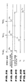
- Figs. 2A to 2E show timing charts of the circuits shown in Fig. 1.
- the utterance detector 9 Whenever a speech such as "start”, “split”, or “stop” is input as shown in Fig. 2A, the utterance detector 9 outputs the signal R1 as shown in Fig. 2B, and the contents of the measuring circuit 14 are stored in the RAM 17.
- the Q output from the flip-flop 12 shown in Fig. 2C When the Q output from the flip-flop 12 shown in Fig. 2C is at low level, the Q output from the flip-flop 12 is at high level. At this time, if a speech is input, the signal R1 from the utterance detector, i.e., a first signal R1a shown in Fig. 2B is output via the AND gate 11 to set the Q output from the flip-flop 12 at high level, thereby starting time measurement by the circuit 14.
- the speech recognition unit 10 recognizes that the input speech is "start"
- the recognition signal T1 is supplied to the RAM controller 16, and the controller 16 designates the address of the first memory area 17a of the RAM 17.
- the Q output of the flip-flop 12 is at high level, time measurement is started by a speech other than "start”.
- start of the time measurement is not problematic at all. If a stopwatch must be used during the time measurement, speech "stop" and “clear” need only be input.
- a speech input of "split" is input, a signal R1b shown in Fig. 2B is supplied to the RAM controller 16 via the AND gate 15 to store a split time measured by the measuring circuit 14 in a designated memory area of the RAM 17 and to designate the next memory area in the RAM 17.
- time data of the measuring circuit 14 obtained when the speech "stop” is input is stored in the RAM 17 as represented by R1c in Fig. 2B, and the circuit 14 continues time measurement until the recognition signal T2 representing "stop” shown in Fig. 2E is output.
- the signal T2 is output, however, since this signal causes the display unit 5 to display the time data output from the circuit 14 and stored in the RAM 17, an operator can check the time data obtained when the speech "stop" is generated.
- the gate g3 is enabled via the OR gate 18, and the content is also supplied to the AND gate 19.
- a one-shot pulse is output from the one-shot circuit 20 to the RAM controller 16 via an AND gate 19.
- the controller 16 sequentially designates an address of the RAM 17 and reads out split time data each time the above pulse is input.
- the sequentially readout split time data are supplied through the gate g3 and displayed on the display unit 5 via the display buffer 4.
- a time from measurement start is stored and displayed as "split".
- a speech "lap” in place of "split", a time interval between preceding and current "lap” speech may be stored and displayed.
- Fig. 3 is a block diagram showing internal circuits of a data memory device which adopts a second embodiment of the present invention.
- a ROM 21 is a read-only memory which stores microprograms and data for controlling the entire system.
- a RAM 22 is a random access memory used for data read/write of various data and including various registers shown in Fig. 4.
- a large number of data memories A0, A1, ... are memories for storing item data including a plurality of characters and numerals such as name and telephone number data or date, time and schedule date.
- Page pointer P designates an address (page) of one of the above data memories. "1" is written in a search flag F during data search and "0" is written therein upon completion of search.
- a counter C counts a 32 Hz count signal or a 32 Hz count signal offset therefrom by a half period.
- a speed recognition unit 23 recognizes speech data input from a microphone 24.
- An utterance detector 25 detects that a speech having a predetermined volume or more is input.
- An oscillator 26 outputs a clock signal of a predetermined period.
- a frequency divider 27 frequency-divides the above clock signal and outputs a count signal of a predetermined period (e.g., 1/32 sec).
- a controller 28 is an arithmetic circuit for performing speech processing corresponding to outputs from the speech recognition unit 23 and the utterance detector 25 or key input processing corresponding to a key input from a key input unit 29 on the basis of the programs stored in the ROM 21.
- Various data obtained by these processing operations are displayed on a dot-matrix display unit 31 by a driver decoder 30.
- Fig. 6 shows a display state change in the display unit 31.
- X0 shown in Fig. 6
- Fig. 5 is a flowchart for explaining an operation performed upon input of the speech.
- step a1 whether a 32 Hz signal is input is checked.
- step a6 whether a speech is input is checked by the utterance detector 25.
- step a6 a signal M, in Fig. 3, is supplied to the speech recognition unit 23 to start a speech recognizing operation.
- step a8 whether F is 1, i.e., whether a search operation is being performed is checked.
- step a11 since data search is not started yet, the flow advances to step a11, and a determining operation for checking whether the recognizing operation is completed is executed. Since the recognizing operation requires several seconds before completion, however, recognition is not completed yet at this moment, and the flow is ended.
- a 32 Hz signal is output thereafter, the flow is ended through steps a1, a6, and a10 without executing any processing operation.
- step a10 When the 32 Hz signal is output, the flow is ended through steps a1 and a Therefore, display contents are not changed at all in either case.
- step a10 At a timing at which the 32 Hz signal is output and recognition completion is determined in step a10, whether the speech is "stop” is checked in step a11. Since the input speech is "start”, the flow advances to step a12, and "1" is set in the flag F. When “1" set in the flag F, this is detected in step a2 each time the 32 Hz signal is input, and the counter C counts the 32 Hz signals in step a3. When it is determined in step a40that the content of the counter C is 0.5 seconds, display change processing is performed in step a5.
- the page pointer P is incremented by one, and the content in the counter C is reset to be zero. Therefore, during data search, the content of the pointer P is incremented by one each time the counter C counts 0.5 seconds, and the contents in the data memories A0, A1, ... are sequentially displayed as shown in Fig. 6.
- step a11 Thereafter, when speech recognition is completed, it is checked in step a11 whether the recognition result is "stop" for stopping data search. If “stop” is determined in step a11, the processing is ended. Therefore, if a speech "stop" is input during data search, search is immediately finished, and data displayed at this moment is still-displayed. For example, if the speech "stop" is input while the content of the data memory A2 is displayed as indicated by X1 in Fig. 6, search is immediately stopped, and the content of the data memory A2 is kept displayed.
- ⁇ hereinafter
- the input speech is determined to be "stop” to temporarily stop search. If the speech recognition result obtained thereafter is other than "stop”, correction based on the recognition result is performed, i.e., search is restarted. Therefore, since no time difference is produced between the display data upon speech input and completion of speech recognition, data search is correctly performed in accordance with a speech input.
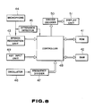
- Fig. 8 is a block diagram showing internal circuits of a stopwatch device which adopts a third embodiment of the present invention.
- a ROM 41 is a read-only memory storing microprograms and data for controlling the entire system.
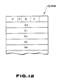
- a RAM 42 is a memory for data read/write of various data and includes various memory areas as shown in Fig. 9.
- a display register X, a stopwatch register Y, and a time count register Z store data displayed on a display unit 51 to be described later, measurement data upon stopwatch operation, and time data representing a current time, respectively.
- a plurality of lap memories M0, M1, ... sequentially store lap data upon stopwatch operation.
- a register C starts counting when a speech is input and stops counting when speech recognition is finished, as will be described in detail later.
- a speech recognition unit 43 recognizes speech data input from a microphone 44.
- An utterance detector 45 detects that a speech having a predetermined sound pressure or more is input from the microphone 44.
- An oscillator 46 outputs a clock signal of a predetermined period.
- a frequency divider 47 frequency-divides the above clock signal and outputs a count signal of a predetermined period (e.g., 1/32 sec).
- a controller 48 is an arithmetic circuit for performing speech processing corresponding to outputs from the speech recognition unit 43 and the utterance detector 45, key input processing corresponding to a key input from a key input unit 49, and count processing corresponding to the count signal from the frequency divider 47, on the basis of the programs stored in the ROM 41. Time data, stopwatch data, and the like obtained by the above processing operations are displayed on a display unit 51 by a decoder driver 50.
- Fig. 10 is a general flowchart showing overall processing controlled by the controller 48 in accordance with the programs stored in the ROM 41.
- step a21 in steps a21 to a23, operations are performed to check whether a count carry signal from the frequency divider 47, a key input from the key input unit 49, and a speech input from the microphone 44 (speech detection of the utterance detector 45) are present, respectively. If it is determined in step a21 that a count carry signal is present, count processing is performed in step a24. In this count processing, current time data or stopwatch data including hour, minute, second, or the like is counted on the basis of the count carry signal. If it is determined in step a22 that a key input is present, key input processing is performed in step a25.
- the key input processing corresponds to various keys (e.g., a mode switching key and a time correction key) operated by the key input unit 49. If it is determined in step a23 that a speech input is present, speech processing is performed in step a26. The speech processing will be described in detail with reference to Fig. 11.
- step b1 whether utterance data is present is checked in step b1. If the utterance data is present, the flow advances to step b2, and speech recognition is started by the speech recognition unit 43 shown in Fig. 8. At the same time, in step b3, the counter C shown in Fig. 9 starts counting. Counting is continuously performed until it is determined in step b4 that speech recognition by the recognition unit 43 is finished. That is, the counter C counts a time interval from detection of the speech input to completion of speech recognition.
- steps b5, b8, b10, and b13 are performed in steps b5, b8, b10, and b13 to check whether the recognition result indicates "start” for starting a stopwatch operation, "lap” for writing a lap time as an elapsed time, “stop” for stopping the stopwatch operation, or “clear” for clearing measurement data, respectively. If “start” is determined in step b5, the flow advances to step b6, and the content of the counter C is added to the stopwatch register Y shown in Fig. 9. Thereafter, in step b7, start processing is performed, i.e., the register Y is sequentially incremented by one, thereby starting time measurement processing for measuring an elapsed time interval from the start.
- the start processing start timing is delayed from an actual start timing (i.e., a timing at which the speech "start" is input) by a time required for speech recognition. Since this time delay is corrected by the processing in step b6, however, the content in the stopwatch register Y corresponds to a correct measurement time from the actual start. For example, even if two seconds are required for speech recognition, since a delay of two seconds is added to the register Y, its content indicates a correct measurement time.
- a value obtained by decrementing the register Y by the content of the counter C i.e., a measurement time obtained upon speech input
- a lap memory Mk 0 1, 2,
- step b10 If "stop” is determined in step b10, the flow advances to step b11, and the register Y is decremented by the content of the counter C. Thereafter, stop processing (for stopping counting of the register Y) is performed in step b12.
- stop processing for stopping counting of the register Y
- the content of the register Y obtained upon speech recognition is completed is directly used as a final elapsed time, it includes an extra time required for speech recognition as in the case of the above lap time. However, since the extra time is subtracted in the processing in step b11, a correct elapsed time is obtained.
- step b13 clear processing for clearing the contents of the register Y is performed in step b14. In this case, since a time difference is not problematic, correction by the counter C need not be performed.
- the counter C counts a time interval from speech input to recognition completion (step b3), and a time difference between the speech input and completion of speech recognition is corrected using the obtained count (steps b6, b9, and b11). Therefore, a very correct measurement time can be obtained. As a result, a stopwatch device based on speech input is realized.
- a data memory device adopting a fourth embodiment of the present invention will be described below.
- An overall arrangement of internal circuits of this device is similar to that shown in Fig. 8 except for microprograms stored in a ROM 41 and the contents of a RAM 42.
- a plurality of data memories A0, A1, ... store various data such as names, telephone numbers, and schedules.
- a page pointer P designates an address of one of the above data memories. "1" is written in a search flag F during data search, and "0" is written therein upon completion of search.
- a counter C counts a 32-Hz signal or a 32 Hz signal offset therefrom by a half period.
- a counter N counts a signal every 0.5 seconds.
- step c1 whether a 32 Hz signal is input is checked. If the 32 Hz signal is input, the flow advances to step c2. In step c2, whether a speech is input is checked. If the speech is input, the counter C is incremented by one (corresponding to 1/32 sec) in step c3. Subsequently, whether the content of the counter C is 0.5 sec is checked in step c4. In this case, 0.5 seconds is a time interval for sequentially switching and displaying the data in the data memories A0, A1, ... (see steps c10 to c13 to be described later). If the content of the counter C is 0.5 seconds, the flow advances to step c5.
- step c5 another counter N is incremented by one, and the content of the counter C is reset to be zero. Counting by the counter N is continuously performed until it is checked in step c6 that speech recognition is completed. That is, the number of display switching times from speech input to completion of speech recognition is counted by the counter N.
- steps c7 and c14 When speech recognition is finished, operations are performed in steps c7 and c14 to check whether the recognition result is "start” for starting data search and whether it is “stop” for stopping data search, respectively. If “start” is determined in step c7, the flow advances to step c8, and the contents of the counters N and C are reset to be zero. Thereafter, "1" is written in the search flag F in step c9. If such start (search start) is performed by speech input, since a time difference between speech input and completion of speech recognition is not problematic, processing for correcting the time difference need not be performed.
- step c10 Until the next speech is input during data search, i.e., while F is kept determined as "1" in step c10, the counter C counts 32 Hz signals in step c11 If it is determined in step c12 that the content of the counter C is 0.5 seconds, display change processing is performed in step c13. In this processing, the page pointer P is incremented by one, and the content of the counter C is reset to be zero. Therefore, during data search, the content of the pointer P is incremented by one each time the counter C counts 0.5 seconds, and the contents of the data memories A0, A1, ... are sequentially displayed as shown in Fig. 14.
- step c16 the pointer P is decremented by the content of the counter N, and the contents of the counters N and C are reset to be zero. Subsequently, "0" is set in the flag F in step c17. In this case, if the content of a page designated by the pointer P upon completion of speech recognition is directly displayed, data including a time required for speech recognition is displayed.
- the counter N counts the number of display switching times from speech input (step c5), and a time difference between display data upon speech input and completion of speech recognition is corrected on the basis of the count (step c16). Therefore, search can be performed at a correct timing in synchronism with speech input. As a result, a data memory device capable of searching based on speech input is realized.
- the present invention can be applied to not only the above stopwatch device or data memory device but also to various instruments such as a video or sound recording device in which data to be controlled varies over time in accordance with speech input.
Landscapes
- Engineering & Computer Science (AREA)
- Physics & Mathematics (AREA)
- General Physics & Mathematics (AREA)
- Theoretical Computer Science (AREA)
- Health & Medical Sciences (AREA)
- Audiology, Speech & Language Pathology (AREA)
- Human Computer Interaction (AREA)
- Computational Linguistics (AREA)
- Multimedia (AREA)
- General Health & Medical Sciences (AREA)
- General Engineering & Computer Science (AREA)
- Acoustics & Sound (AREA)
- Electric Clocks (AREA)
Applications Claiming Priority (4)
| Application Number | Priority Date | Filing Date | Title |
|---|---|---|---|
| JP90337/88U | 1988-07-07 | ||
| JP1988090341U JPH0641195Y2 (ja) | 1988-07-07 | 1988-07-07 | 音声認識手段を備えた電子機器 |
| JP90341/88U | 1988-07-07 | ||
| JP1988090337U JPH0213297U (fr) | 1988-07-07 | 1988-07-07 |
Publications (2)
| Publication Number | Publication Date |
|---|---|
| EP0350064A2 true EP0350064A2 (fr) | 1990-01-10 |
| EP0350064A3 EP0350064A3 (fr) | 1991-12-27 |
Family
ID=26431831
Family Applications (1)
| Application Number | Title | Priority Date | Filing Date |
|---|---|---|---|
| EP19890112477 Withdrawn EP0350064A3 (fr) | 1988-07-07 | 1989-07-07 | Appareil de reconnaissance de voix |
Country Status (3)
| Country | Link |
|---|---|
| US (1) | US4984274A (fr) |
| EP (1) | EP0350064A3 (fr) |
| KR (1) | KR920009959B1 (fr) |
Families Citing this family (7)
| Publication number | Priority date | Publication date | Assignee | Title |
|---|---|---|---|---|
| JPH05207916A (ja) * | 1992-01-30 | 1993-08-20 | Sanyo Electric Co Ltd | パーティー演出装置 |
| JP2986345B2 (ja) * | 1993-10-18 | 1999-12-06 | インターナショナル・ビジネス・マシーンズ・コーポレイション | 音声記録指標化装置及び方法 |
| GB2296349A (en) * | 1994-12-19 | 1996-06-26 | Secr Defence | Maintaining order of input data events |
| US7171365B2 (en) * | 2001-02-16 | 2007-01-30 | International Business Machines Corporation | Tracking time using portable recorders and speech recognition |
| CA2554044C (fr) * | 2004-01-30 | 2009-07-07 | Oh, Seung-Yeop | Perle de polystyrene expanse a peau fonctionnelle, procede de fabrication correspondant, et produit en polystyrene expanse fonctionnel ainsi que procede de fabrication correspondant |
| US8886527B2 (en) * | 2008-06-10 | 2014-11-11 | Nec Corporation | Speech recognition system to evaluate speech signals, method thereof, and storage medium storing the program for speech recognition to evaluate speech signals |
| US9153229B2 (en) * | 2011-11-21 | 2015-10-06 | Robert Bosch Gmbh | Methods and systems for adapting grammars in hybrid speech recognition engines for enhancing local SR performance |
Family Cites Families (9)
| Publication number | Priority date | Publication date | Assignee | Title |
|---|---|---|---|---|
| GB1569450A (en) * | 1976-05-27 | 1980-06-18 | Nippon Electric Co | Speech recognition system |
| JPS56133678A (en) * | 1980-03-25 | 1981-10-19 | Sharp Corp | Timepiece device |
| JPS5782899A (en) * | 1980-11-12 | 1982-05-24 | Canon Kk | Voice recognition apparatus |
| CH644246B (fr) * | 1981-05-15 | 1900-01-01 | Asulab Sa | Dispositif d'introduction de mots a commande par la parole. |
| CH645501GA3 (fr) * | 1981-07-24 | 1984-10-15 | ||
| JPS5861040A (ja) * | 1981-10-06 | 1983-04-11 | Nissan Motor Co Ltd | 車載機器の音声指令制御装置 |
| JPS5870292A (ja) * | 1981-10-22 | 1983-04-26 | 日産自動車株式会社 | 車両用音声認識装置 |
| JPS58115497A (ja) * | 1981-12-28 | 1983-07-09 | シャープ株式会社 | 音声認識方法 |
| GB2125990B (en) * | 1982-08-20 | 1985-09-25 | Asulab Sa | Speech-controlled electronic watch |
-
1989
- 1989-06-28 US US07/372,868 patent/US4984274A/en not_active Expired - Lifetime
- 1989-06-30 KR KR1019890009262A patent/KR920009959B1/ko not_active Expired
- 1989-07-07 EP EP19890112477 patent/EP0350064A3/fr not_active Withdrawn
Also Published As
| Publication number | Publication date |
|---|---|
| KR920009959B1 (ko) | 1992-11-06 |
| KR900002236A (ko) | 1990-02-28 |
| EP0350064A3 (fr) | 1991-12-27 |
| US4984274A (en) | 1991-01-08 |
Similar Documents
| Publication | Publication Date | Title |
|---|---|---|
| US4247905A (en) | Memory clear system | |
| US4769796A (en) | Time management scheduler | |
| US4831605A (en) | Electronic time measuring apparatus including past record display means | |
| US4984274A (en) | Speech recognition apparatus with means for preventing errors due to delay in speech recognition | |
| KR950034106A (ko) | 헤더 데이타의 오류 보정을 행하는 cd-rom 디코더 | |
| US4330840A (en) | Multi-function electronic digital watch | |
| EP0537804B1 (fr) | Dispositif d'enregistrement de la parole avec compression des parties silencieuses | |
| JP3033849B2 (ja) | 血圧記憶装置 | |
| JP2000350168A (ja) | 画像信号処理方法および画像信号処理装置 | |
| JPH1152984A (ja) | 音声認識装置における認識対象表示方式 | |
| JPH0641195Y2 (ja) | 音声認識手段を備えた電子機器 | |
| JP3265604B2 (ja) | 音声発生装置 | |
| JP2508571Y2 (ja) | ストップウオッチ | |
| SU1456947A1 (ru) | Устройство дл выборки информации при ее отображении | |
| JP2539338Y2 (ja) | 高度計 | |
| KR940008449A (ko) | 다중분할화면을 이용한 채널검색방법 및 장치 | |
| JPH05306940A (ja) | 測位データ記録装置 | |
| JPH039030Y2 (fr) | ||
| JPH0628718Y2 (ja) | ストップウォッチ | |
| JP4199392B2 (ja) | 電子式圧力測定装置 | |
| SU1300478A1 (ru) | Устройство дл отладки программ | |
| SU1585830A1 (ru) | Устройство дл отображени информации на экране телевизионного индикатора | |
| SU1642462A1 (ru) | Устройство дл поиска информации | |
| SU1615726A1 (ru) | Устройство дл контрол хода программ | |
| JPS58218676A (ja) | 世界時計の表示部構成 |
Legal Events
| Date | Code | Title | Description |
|---|---|---|---|
| PUAI | Public reference made under article 153(3) epc to a published international application that has entered the european phase |
Free format text: ORIGINAL CODE: 0009012 |
|
| AK | Designated contracting states |
Kind code of ref document: A2 Designated state(s): DE FR GB |
|
| 17P | Request for examination filed |
Effective date: 19910322 |
|
| PUAL | Search report despatched |
Free format text: ORIGINAL CODE: 0009013 |
|
| AK | Designated contracting states |
Kind code of ref document: A3 Designated state(s): DE FR GB |
|
| 17Q | First examination report despatched |
Effective date: 19921127 |
|
| STAA | Information on the status of an ep patent application or granted ep patent |
Free format text: STATUS: THE APPLICATION IS DEEMED TO BE WITHDRAWN |
|
| 18D | Application deemed to be withdrawn |
Effective date: 19931201 |