EP0350295A2 - Appareil de contrôle pour véhicule - Google Patents
Appareil de contrôle pour véhicule Download PDFInfo
- Publication number
- EP0350295A2 EP0350295A2 EP89306843A EP89306843A EP0350295A2 EP 0350295 A2 EP0350295 A2 EP 0350295A2 EP 89306843 A EP89306843 A EP 89306843A EP 89306843 A EP89306843 A EP 89306843A EP 0350295 A2 EP0350295 A2 EP 0350295A2
- Authority
- EP
- European Patent Office
- Prior art keywords
- controller
- unit
- engine
- auto
- cruising
- Prior art date
- Legal status (The legal status is an assumption and is not a legal conclusion. Google has not performed a legal analysis and makes no representation as to the accuracy of the status listed.)
- Granted
Links
Images


Classifications
-
- B—PERFORMING OPERATIONS; TRANSPORTING
- B60—VEHICLES IN GENERAL
- B60L—PROPULSION OF ELECTRICALLY-PROPELLED VEHICLES; SUPPLYING ELECTRIC POWER FOR AUXILIARY EQUIPMENT OF ELECTRICALLY-PROPELLED VEHICLES; ELECTRODYNAMIC BRAKE SYSTEMS FOR VEHICLES IN GENERAL; MAGNETIC SUSPENSION OR LEVITATION FOR VEHICLES; MONITORING OPERATING VARIABLES OF ELECTRICALLY-PROPELLED VEHICLES; ELECTRIC SAFETY DEVICES FOR ELECTRICALLY-PROPELLED VEHICLES
- B60L15/00—Methods, circuits, or devices for controlling the traction-motor speed of electrically-propelled vehicles
-
- F—MECHANICAL ENGINEERING; LIGHTING; HEATING; WEAPONS; BLASTING
- F02—COMBUSTION ENGINES; HOT-GAS OR COMBUSTION-PRODUCT ENGINE PLANTS
- F02D—CONTROLLING COMBUSTION ENGINES
- F02D41/00—Electrical control of supply of combustible mixture or its constituents
- F02D41/24—Electrical control of supply of combustible mixture or its constituents characterised by the use of digital means
- F02D41/26—Electrical control of supply of combustible mixture or its constituents characterised by the use of digital means using computer, e.g. microprocessor
- F02D41/28—Interface circuits
-
- F—MECHANICAL ENGINEERING; LIGHTING; HEATING; WEAPONS; BLASTING
- F02—COMBUSTION ENGINES; HOT-GAS OR COMBUSTION-PRODUCT ENGINE PLANTS
- F02D—CONTROLLING COMBUSTION ENGINES
- F02D41/00—Electrical control of supply of combustible mixture or its constituents
- F02D41/24—Electrical control of supply of combustible mixture or its constituents characterised by the use of digital means
- F02D41/26—Electrical control of supply of combustible mixture or its constituents characterised by the use of digital means using computer, e.g. microprocessor
- F02D41/266—Electrical control of supply of combustible mixture or its constituents characterised by the use of digital means using computer, e.g. microprocessor the computer being backed-up or assisted by another circuit, e.g. analogue
-
- B—PERFORMING OPERATIONS; TRANSPORTING
- B60—VEHICLES IN GENERAL
- B60W—CONJOINT CONTROL OF VEHICLE SUB-UNITS OF DIFFERENT TYPE OR DIFFERENT FUNCTION; CONTROL SYSTEMS SPECIALLY ADAPTED FOR HYBRID VEHICLES; ROAD VEHICLE DRIVE CONTROL SYSTEMS FOR PURPOSES NOT RELATED TO THE CONTROL OF A PARTICULAR SUB-UNIT
- B60W50/00—Details of control systems for road vehicle drive control not related to the control of a particular sub-unit, e.g. process diagnostic or vehicle driver interfaces
- B60W50/02—Ensuring safety in case of control system failures, e.g. by diagnosing, circumventing or fixing failures
- B60W50/0205—Diagnosing or detecting failures; Failure detection models
- B60W2050/021—Means for detecting failure or malfunction
-
- F—MECHANICAL ENGINEERING; LIGHTING; HEATING; WEAPONS; BLASTING
- F02—COMBUSTION ENGINES; HOT-GAS OR COMBUSTION-PRODUCT ENGINE PLANTS
- F02B—INTERNAL-COMBUSTION PISTON ENGINES; COMBUSTION ENGINES IN GENERAL
- F02B1/00—Engines characterised by fuel-air mixture compression
- F02B1/02—Engines characterised by fuel-air mixture compression with positive ignition
- F02B1/04—Engines characterised by fuel-air mixture compression with positive ignition with fuel-air mixture admission into cylinder
-
- F—MECHANICAL ENGINEERING; LIGHTING; HEATING; WEAPONS; BLASTING
- F02—COMBUSTION ENGINES; HOT-GAS OR COMBUSTION-PRODUCT ENGINE PLANTS
- F02D—CONTROLLING COMBUSTION ENGINES
- F02D41/00—Electrical control of supply of combustible mixture or its constituents
- F02D41/02—Circuit arrangements for generating control signals
- F02D41/18—Circuit arrangements for generating control signals by measuring intake air flow
- F02D41/187—Circuit arrangements for generating control signals by measuring intake air flow using a hot wire flow sensor
Definitions
- the present invention relates to an apparatus for controlling a vehicle having diversified control items such as an automobile and, more particularly to a vehicle control apparatus suitable for raising the safety of an automobile provided with an internal engine such as a gasoline engine.
- controllers using a micro-computer have come to be employed in recent years.
- a variety of controllers with a micro-computer have now been applied to automobiles for the purposes of controlling a power transmission mechanism and an air conditioner, suspension control, or the like, in addition to various controls concerning the engine, in individual units.
- Some of conventional unit controllers each are provided with a self-diagnosis function and a fail-safe function. However, they have no problem so long as each of the unit controllers exhibits reliably its fail-safe function but does not take into consideration the fact that when any abnormality occurs in any of various load driving circuits controlled by the unit controllers, the fail-safe function cannot be obtained.
- An object of the present invention is to provide a vehicle control apparatus which backs up the fail-safe function for a plurality of unit controllers of a vehicle and can always secure reliably sufficient safety of the vehicle.
- an object of the present invention is to provide a vehicle control apparatus in which a fail safe function provided for at least one of a plurality of unit controllers is backed up by at the other unit controller or controllers and sufficient safety can be always secured reliably.
- the object described above can be accomplished by allowing at least one of a plurality of unit controllers to monitor abnormality of the other controller or controllers and to change its control mode of the unit controller having monitored of the abnormality so as to cope with the abnormality when the abnormality occurs in one of the unit controllers.
- the object described above can be accomplished also by monitoring commonly a plurality of unit controllers and changing the control modes by the other unit controllers than the unit controller or controllers from which the abnormality is detected as the monitor result.
- At least one of the other unit controllers change its control mode to compensate for the drop of safety caused thereby, such as the decrease in a fuel supply quantity by an engine controller as one of the unit controllers for the abnormal increase in intake air due to abnormality of an auto-cruising controller as the other unit controller, for example, and since this counter-measure is provided, reliable back-up can always be obtained.
- a vehicle control apparatus according to the present invention will be described on its embodiments.
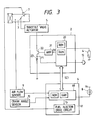
- an engine controller 6 and an auto-cruising controller 2 are employed as a plurality of unit controllers.
- the engine controller 6 executes calculation according to the following equation (1) on the basis of r.p.m. (N) of an automobile engine 1 detected by a crank angle sensor 10 and an intake air flow rate (Qa) detected by an air flow sensor 9 mounted in an intake passage, thereby to obtain a fuel injection pulse width Tp.
- Tp f (Qa ⁇ N) (1)
- the engine controller 6 supplies a pulse signal having this fuel injection pulse width Tp to a fuel injector drive circuit 61 which inputs a signal to a fuel injection valve 7 provided on the intake passage to drive it according to the fuel injection pulse width Tp thereby to execute a control so as to obtain a predetermined air-fuel ratio.
- the engine controller 6 exchanges predetermined data with the auto-cruising controller 2, diagnosis the function of the auto-cruising controller 2, executes the operations to be later described when any abnormality is detected in this auto-cruising controller 2, and turns on an alarm lamp 8 to give an alarm to the user.
- the auto-cruising controller 2 controls the rotating speed of the engine so that the vehicle travels automatically at a constant speed set by the user (driver) and the relation between the set speed by the user and the traveling speed of the car is shown in Fig. 2.
- the auto-cruising controller 2 includes a micro-computer 20, an amplification circuit 21, an output driving device (power transistor) 22, a resistor 23 and a speed set switch 15.
- the micro-computer 20 receives, as a set car speed, the car speed from the car speed sensor 4, which car speed is set by the user through a pushing operation of the speed set switch 15 and its value being one at the time the speed set switch 15 is pushed, and, stores the set car speed in RAM, calculates an opening signal (S1) of the throttle valve 3 using the set car speed, controls the throttle valve actuator 5 through the amplification circuit 21 and the output driving device 22 to control the opening of the throttle valve 3 and executes feedback control so that the actual car speed detected from the car speed sensor 4 converges to the set car speed.
- S1 opening signal
- a current flowing through the output driving device that is, a current supplied to the throttle valve actuator 5 flows through the resistor 23 so that a predetermined signal F1 can be obtained. Therefore, the micro-computer 20 receives this signal F1, makes self-diagnosis or self-checking by judging whether or not its level is within a predetermined range and executes a fail-safe control.
- a data transfer system by SCI Serial Communication Interface
- SCI Serial Communication Interface
- the data transfer can be made between the auto-cruising controller 2 and the engine controller 6.
- predetermined data are also taken into by the micro-computer 60 of the engine controller 6, an among the data of the micro-computer 60, some necessary data are also transferred to the micro-computer 20.
- the fail-safe control at this time can only switch the control signal for the output driving device 22 to the OFF direction through the amplification circuit 21 and cannot at all cope with the short-circuit trouble of this output driving device 22.
- the micro-computer 20 in the auto-cruising controller 2 detects the current flowing through the output driving device 22 from the signal F1 resulting from the voltage drop of the resistor 23 as described above, makes judgement for the self-diagnosis processing depending on whether or not the current exceeds a predetermined value and transmits the result to the engine controller 6.
- the micro-computer 60 of the engine controller 6 transmits the data representing that "the throttle valve 3 is fully open due to the short-circuit of the output driving device 22" to the micro-computer 60 of the engine controller 6.
- the micro-computer 60 reduces the pulse width Tp described already so as to reduce the fuel quantity supplied from the fuel injection valve 7, thus to limit the increase in the number of revolution of the engine 1, to light the alarm lamp 8 and to give the alarm to the user.
- the auto-cruising controller 2 as one of the unit controllers can be backed up by the engine controller 6 as the other unit controller even when the fail-safe function of the auto-cruising controller 2 does not operate effectively, and the uncontrolled operation of the engine 1 can be prevented reliably.
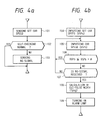
- the micro-computer 20 of the auto-cruising controller 2 executes the processing shown in Fig. 4a in each predetermined period.
- a set car speed value which is set by the driver and inputted into the micro-computer 20, is sent to the engine controller 6 at step 101.
- Self-diagnosis or self-checking such as whether or not the current F1 is in a predetermined range is made at step 102, and its result is transferred to the engine controller 6 at the subsequent step 103.
- an NG signal representing not-normal condition is transferred when any abnormality is detected.
- the micro-computer 60 of the engine controller 6 executes the processing shown in Fig. 4b. Namely, the set car speed value VSPs is taken into the micro-computer 60 from the micro-computer 20 at step 104 and an actual car speed VSPn is received from the speed sensor 4 through the micro-computer 20 at step 105. At the subsequent step 106, whether or not this actual car speed VSPn exceeds the sum of the set car speed value VSPs and a value ⁇ which is added in order to provide the former with a predetermined allowance range is judged. If the result proves to be NO, the flow proceeds to step 107, where whether or not the NG signal is received is judged.
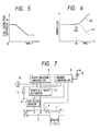
- the fuel correction coefficient ⁇ changes in a decreasing direction as a function of the time t elapsed from the point (to) of the occurrence of abnormality as shown in Fig. 5, for example.
- the control by which the number of revolution N of the engine is decreased with the passage of time t after the point (to) of the occurrence of abnormality in the auto-cruising controller 2 is made automatically as represented by dashed line 111 in Fig. 6, and back-up can be obtained reliably.
- the characteristics represented by solid line 110 in this drawing show the case where back-up by this embodiment cannot be obtained, and represents that the number of revolution of the engine increases with the passage of time and a critical state will be reached.
- the auto-cruising controller 2 and the engine controller 6 make direct mutual data communication to obtain the necessary back-up data communication to obtain the necessary back-up function.
- FIG. 7 represents a structural example of a vehicle control apparatus including an auto-cruising controller and an engine controller as a plurality of unit controllers that do not have a mutual data communication function.
- the construction in Fig. 7 is the same as one in Fig. 1 except that a car speed setting switch 15 is connected to a micro-computer 60 so that a set car speed can be inputted into the micro-computer 60. Therefore, explanation about the other construction is omitted. Further, the same parts or apparatus in Fig. 7 as ones in Fig. 1 are referred to by the same reference numerals.
- step 112 the signal of the car speed setting switch 15 for setting a car speed on the auto-cruising controller 2 is received to judge whether or not a car speed is set.
- the set car speed is received at step 113 to obtain the data VSPs. Processing is completed there if the results at the steps 112 is NO.
- step 114 the actual car speed VSPn is taken into and at the subsequent step 115, this car speed VSPn is compared with a certain predetermined car speed reference value VSPs + ⁇ .
- the car speed value VSPn is more than the car speed reference value VSPs + ⁇ , judgement is made to the effect that any abnormality occurs in the auto-cruising controller 2 and here the next step 116 is executed. Namely, the normal fuel injection pulse width Tp is multiplied by the correction coefficient ⁇ to execute the fuel injection pulse width T PNG at the time of abnormality and the alarm lamp 8 is lit at the subsequent processing of step 117 to complete the processing.
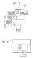
- Fig. 9 shows still another embodiment of the present invention.
- the auto-cruising controller 2 and the engine controller 6 do not individually make the abnormality judgement but a monitor 12 disposed separately from, and independently of, them makes the abnormality judgement.
- the monitor 12 is constructed by a micro-computer 62 as shown in Fig. 10. Data communication between the auto-cruising controller 2, the engine controller 6 and the monitor 12 is carried out by SCI.
- the present invention has been explained with reference to the foregoing embodiments wherein abnormality detection between the engine controller and the auto-cruising controller and between them and the monitor is made, the present invention is not particularly limited thereto but can of course be practised in other ways. Needless to say, the present invention may be constituted for the purpose of backing up between the unit controllers with any other control items as the control object.
- the present invention can be applied to any controllers such as an air conditioner, a suspension controller, a power transmission controller, and the like, that are mounted into a vehicle, as the unit controller, and back-up can of course be obtained between these controllers when the abnormality diagnosis and fail-safe function therebetween cannot be obtained.
- controllers such as an air conditioner, a suspension controller, a power transmission controller, and the like
- sufficient back-up can be obtained at the time of the occurrence of abnormality in various unit controllers such as the auto-cruising controller and the engine controller of a vehicle, and there can be obtained the effect that safety can be always secured reliably.
Landscapes
- Engineering & Computer Science (AREA)
- Computer Hardware Design (AREA)
- General Engineering & Computer Science (AREA)
- Mechanical Engineering (AREA)
- Microelectronics & Electronic Packaging (AREA)
- Combustion & Propulsion (AREA)
- Chemical & Material Sciences (AREA)
- Power Engineering (AREA)
- Transportation (AREA)
- Combined Controls Of Internal Combustion Engines (AREA)
- Control Of Driving Devices And Active Controlling Of Vehicle (AREA)
- Electrical Control Of Air Or Fuel Supplied To Internal-Combustion Engine (AREA)
- Controls For Constant Speed Travelling (AREA)
- Control Of Vehicle Engines Or Engines For Specific Uses (AREA)
Applications Claiming Priority (2)
| Application Number | Priority Date | Filing Date | Title |
|---|---|---|---|
| JP63170013A JP3117442B2 (ja) | 1988-07-07 | 1988-07-07 | 車両制御装置 |
| JP170013/88 | 1988-07-07 |
Publications (3)
| Publication Number | Publication Date |
|---|---|
| EP0350295A2 true EP0350295A2 (fr) | 1990-01-10 |
| EP0350295A3 EP0350295A3 (en) | 1990-10-10 |
| EP0350295B1 EP0350295B1 (fr) | 1995-02-01 |
Family
ID=15896975
Family Applications (1)
| Application Number | Title | Priority Date | Filing Date |
|---|---|---|---|
| EP89306843A Expired - Lifetime EP0350295B1 (fr) | 1988-07-07 | 1989-07-06 | Appareil de contrôle pour véhicule |
Country Status (5)
| Country | Link |
|---|---|
| US (1) | US5047944A (fr) |
| EP (1) | EP0350295B1 (fr) |
| JP (1) | JP3117442B2 (fr) |
| KR (1) | KR940004808B1 (fr) |
| DE (1) | DE68920922T2 (fr) |
Cited By (5)
| Publication number | Priority date | Publication date | Assignee | Title |
|---|---|---|---|---|
| EP0564711A3 (en) * | 1991-12-19 | 1994-10-26 | Mita Industrial Co Ltd | Image forming apparatus having functional redundancy system |
| EP0551631A3 (en) * | 1991-12-19 | 1994-10-26 | Mita Industrial Co Ltd | Functional redundancy control system |
| WO2001075533A1 (fr) * | 2000-03-30 | 2001-10-11 | Llanelli Radiators Limited | Unite de commande intelligente |
| WO2017205457A1 (fr) * | 2016-05-25 | 2017-11-30 | NavResearch, Inc. | Système et procédé d'évaluation de véhicule et utilisations associées |
| EP2986500B1 (fr) * | 2013-04-19 | 2020-05-27 | CIRCOR Pumps North America, LLC | Système de refroidissment à débit variable et méthode associée |
Families Citing this family (25)
| Publication number | Priority date | Publication date | Assignee | Title |
|---|---|---|---|---|
| DE4110105C2 (de) * | 1990-03-28 | 2001-07-26 | Nissan Motor | Verfahren und Steuervorrichtung zur ausfallsicheren Steuerung des Ausgangsdrehmomentes eines mit einer Brennkraftmaschine versehenen Kraftfahrzeuges |
| JPH0510201A (ja) * | 1991-07-04 | 1993-01-19 | Fuji Heavy Ind Ltd | 車輌の制御方法 |
| JP3309437B2 (ja) * | 1992-08-19 | 2002-07-29 | 株式会社デンソー | 車両の自己診断装置 |
| US5325082A (en) * | 1992-11-19 | 1994-06-28 | Rodriguez Juan C | Comprehensive vehicle information storage system |
| DE4320111C2 (de) * | 1993-06-17 | 2003-02-27 | Bosch Gmbh Robert | Verfahren und Vorrichtung zur Steuerung eines Fahrzeugs |
| US7082359B2 (en) * | 1995-06-07 | 2006-07-25 | Automotive Technologies International, Inc. | Vehicular information and monitoring system and methods |
| US5687081A (en) * | 1994-12-30 | 1997-11-11 | Crown Equipment Corporation | Lift truck control system |
| US5706199A (en) * | 1995-07-17 | 1998-01-06 | Cummins Engine Company, Inc. | System for controlling engine speed in response to detection of vehicle speed signal tampering |
| US5673668A (en) * | 1996-08-05 | 1997-10-07 | Ford Global Technologies, Inc. | Method and apparatus for electronic throttle monitoring |
| JP3613028B2 (ja) * | 1998-10-08 | 2005-01-26 | 株式会社デンソー | メモリチェック装置及びチェック方法 |
| US6112148A (en) * | 1998-12-18 | 2000-08-29 | Cummins Engine Co., Inc. | System and method for controlling diagnostic annunciators |
| KR100435669B1 (ko) * | 2001-07-24 | 2004-06-12 | 현대자동차주식회사 | 연료전지 전기자동차의 수소 연료 제어 시스템 및 그 제어방법 |
| KR100949659B1 (ko) * | 2001-08-24 | 2010-03-26 | 루크 라멜렌 운트 쿠프룽스바우 베타일리궁스 카게 | 어댑터 커넥터 |
| JP3967599B2 (ja) | 2002-01-28 | 2007-08-29 | 株式会社デンソー | 車両用電子制御装置 |
| JP3791434B2 (ja) * | 2002-02-28 | 2006-06-28 | 株式会社デンソー | 車両用電子制御装置 |
| US7117390B1 (en) * | 2002-05-20 | 2006-10-03 | Sandia Corporation | Practical, redundant, failure-tolerant, self-reconfiguring embedded system architecture |
| JP4848027B2 (ja) * | 2004-01-30 | 2011-12-28 | 日立オートモティブシステムズ株式会社 | 車両制御装置 |
| EP2177413B1 (fr) | 2004-07-15 | 2015-02-25 | Hitachi, Ltd. | Système de commande de véhicule |
| JP4827535B2 (ja) * | 2006-01-20 | 2011-11-30 | 日立オートモティブシステムズ株式会社 | 自動車用電子制御装置 |
| DE102007053085A1 (de) * | 2007-11-07 | 2009-05-14 | Robert Bosch Gmbh | Verfahren zur Stabilisierung eines Reglers und entsprechende Reglervorrichtung |
| DE102008034150A1 (de) * | 2008-07-22 | 2010-01-28 | Continental Automotive Gmbh | Sicherheitsüberwachung mit Hilfe von Verbindungsleitungen zwischen Steuergeräten eines Kraftfahrzeugs |
| CN105191048A (zh) | 2013-03-14 | 2015-12-23 | 汽车能源供应公司 | 异常诊断装置 |
| JP2016125436A (ja) * | 2015-01-07 | 2016-07-11 | 日立オートモティブシステムズ株式会社 | エンジン制御システム |
| JP7451890B2 (ja) * | 2019-06-27 | 2024-03-19 | 株式会社デンソー | 車両の駆動システム |
| CN115596565B (zh) * | 2022-10-31 | 2025-09-09 | 广州汽车集团股份有限公司 | 控制方法、装置、车辆、电子设备及存储介质 |
Family Cites Families (16)
| Publication number | Priority date | Publication date | Assignee | Title |
|---|---|---|---|---|
| JPS5815730A (ja) * | 1981-07-21 | 1983-01-29 | Nippon Denso Co Ltd | 車両用速度制御装置 |
| US4472777A (en) * | 1981-12-23 | 1984-09-18 | Ford Motor Company | Engine control apparatus for vehicle speed |
| EP0110885B1 (fr) * | 1982-06-16 | 1989-09-06 | The Boeing Company | Systeme de pilote automatique de direction de vol |
| JPS5961740A (ja) * | 1982-10-01 | 1984-04-09 | Fuji Heavy Ind Ltd | 内燃機関用電子制御装置の故障診断表示装置 |
| DE3313688A1 (de) * | 1983-04-15 | 1984-10-25 | Zahnräderfabrik Renk AG, 8900 Augsburg | Elektronische steuereinrichtung fuer eine antriebsanlage |
| JPS60135332A (ja) * | 1983-12-24 | 1985-07-18 | Toshiba Corp | 自動車制御システムの保護装置 |
| JPS60147553A (ja) * | 1984-01-11 | 1985-08-03 | Nippon Denso Co Ltd | 自己診断機能を有する制御装置 |
| JPS60163731A (ja) * | 1984-02-07 | 1985-08-26 | Nissan Motor Co Ltd | 車速制御装置 |
| JPS60176830A (ja) * | 1984-02-23 | 1985-09-10 | Diesel Kiki Co Ltd | 定車速走行制御装置 |
| GB2162341B (en) * | 1984-07-27 | 1988-02-03 | Ae Plc | Automatic vehicle speed control system |
| JPS6149154A (ja) * | 1984-08-15 | 1986-03-11 | Japan Electronic Control Syst Co Ltd | 自動車用制御装置 |
| JPH064389B2 (ja) * | 1986-04-01 | 1994-01-19 | マツダ株式会社 | 自動車の定速走行制御装置 |
| JPS62279245A (ja) * | 1986-05-29 | 1987-12-04 | Nissan Motor Co Ltd | 空燃比制御装置 |
| JPS6334243A (ja) * | 1986-07-30 | 1988-02-13 | Mazda Motor Corp | 自動車の定速走行装置 |
| JPH0767897B2 (ja) * | 1986-09-17 | 1995-07-26 | 日本電装株式会社 | 車両の異常警告装置 |
| DE3786894T2 (de) * | 1986-11-29 | 1993-12-09 | Aisin Seiki | Fahrzeuggeschwindigkeitssteuersystem für Motorfahrzeuge mit Steuersystem für das automatische Getriebe. |
-
1988
- 1988-07-07 JP JP63170013A patent/JP3117442B2/ja not_active Expired - Lifetime
-
1989
- 1989-06-29 US US07/372,829 patent/US5047944A/en not_active Expired - Lifetime
- 1989-07-06 EP EP89306843A patent/EP0350295B1/fr not_active Expired - Lifetime
- 1989-07-06 DE DE68920922T patent/DE68920922T2/de not_active Expired - Fee Related
- 1989-07-07 KR KR1019890009691A patent/KR940004808B1/ko not_active Expired - Fee Related
Cited By (9)
| Publication number | Priority date | Publication date | Assignee | Title |
|---|---|---|---|---|
| EP0564711A3 (en) * | 1991-12-19 | 1994-10-26 | Mita Industrial Co Ltd | Image forming apparatus having functional redundancy system |
| EP0551631A3 (en) * | 1991-12-19 | 1994-10-26 | Mita Industrial Co Ltd | Functional redundancy control system |
| US5463545A (en) * | 1991-12-19 | 1995-10-31 | Mita Industrial Co., Ltd. | Functional redundancy control system |
| EP0784240A3 (fr) * | 1991-12-19 | 1997-07-23 | Mita Industrial Co. Ltd. | Appareil de formation d'images muni d'un système de redondance fonctionnelle |
| WO2001075533A1 (fr) * | 2000-03-30 | 2001-10-11 | Llanelli Radiators Limited | Unite de commande intelligente |
| EP2986500B1 (fr) * | 2013-04-19 | 2020-05-27 | CIRCOR Pumps North America, LLC | Système de refroidissment à débit variable et méthode associée |
| WO2017205457A1 (fr) * | 2016-05-25 | 2017-11-30 | NavResearch, Inc. | Système et procédé d'évaluation de véhicule et utilisations associées |
| US10417839B2 (en) | 2016-05-25 | 2019-09-17 | Navigation Research Company | System and method for vehicle assessment and uses thereof |
| US11367317B2 (en) | 2016-05-25 | 2022-06-21 | Navigation Research Company | System and method for vehicle assessment and uses thereof |
Also Published As
| Publication number | Publication date |
|---|---|
| JP3117442B2 (ja) | 2000-12-11 |
| US5047944A (en) | 1991-09-10 |
| JPH0220456A (ja) | 1990-01-24 |
| EP0350295B1 (fr) | 1995-02-01 |
| DE68920922D1 (de) | 1995-03-16 |
| EP0350295A3 (en) | 1990-10-10 |
| DE68920922T2 (de) | 1995-08-24 |
| KR940004808B1 (ko) | 1994-06-01 |
| KR900001542A (ko) | 1990-02-27 |
Similar Documents
| Publication | Publication Date | Title |
|---|---|---|
| EP0350295A2 (fr) | Appareil de contrôle pour véhicule | |
| US6718254B2 (en) | Intake air quantity control system for internal combustion engine | |
| US5048482A (en) | Device for controlling an operating characteristic of an internal combustion engine | |
| JPS6080969A (ja) | パワ−ステアリング装置 | |
| JPH0419376B2 (fr) | ||
| JPH0578661B2 (fr) | ||
| US12146458B2 (en) | EGR pump system and control method of EGR pump | |
| DE3230211C2 (fr) | ||
| JPH01116272A (ja) | 内燃機関の調節装置 | |
| US20040186659A1 (en) | Engine air-intake control device and engine air-intake control method | |
| US6619259B2 (en) | Electronically controlled throttle control system | |
| US5778852A (en) | Functionally monitored fuel injection system | |
| EP0453439B1 (fr) | Regulateur electronique de vanne-papillon avec systeme de surveillance en continu des defaillances | |
| US6807477B2 (en) | Electronic control system and method having monitor program monitoring function | |
| US4577605A (en) | Arrangement for controlling a fuel metering apparatus and having an emergency cotrol system | |
| US4823751A (en) | Control apparatus for an injection pump | |
| DE3921011A1 (de) | Drosselventilregler | |
| JPH03262757A (ja) | 電源異常回避機能付き車両制御装置 | |
| JPH0441235Y2 (fr) | ||
| JPH0311410Y2 (fr) | ||
| JPH03290041A (ja) | 内燃機関のスロットル弁制御装置 | |
| JPH0477168B2 (fr) | ||
| JPH0331531A (ja) | 内燃機関のスロットル弁制御装置 | |
| JPH0460143A (ja) | 内燃機関の吸気装置 | |
| JPS6131642A (ja) | アイドル制御弁駆動回路 |
Legal Events
| Date | Code | Title | Description |
|---|---|---|---|
| PUAI | Public reference made under article 153(3) epc to a published international application that has entered the european phase |
Free format text: ORIGINAL CODE: 0009012 |
|
| 17P | Request for examination filed |
Effective date: 19890803 |
|
| AK | Designated contracting states |
Kind code of ref document: A2 Designated state(s): DE FR GB |
|
| PUAL | Search report despatched |
Free format text: ORIGINAL CODE: 0009013 |
|
| AK | Designated contracting states |
Kind code of ref document: A3 Designated state(s): DE FR GB |
|
| 17Q | First examination report despatched |
Effective date: 19920410 |
|
| GRAA | (expected) grant |
Free format text: ORIGINAL CODE: 0009210 |
|
| AK | Designated contracting states |
Kind code of ref document: B1 Designated state(s): DE FR GB |
|
| REF | Corresponds to: |
Ref document number: 68920922 Country of ref document: DE Date of ref document: 19950316 |
|
| ET | Fr: translation filed | ||
| PLBE | No opposition filed within time limit |
Free format text: ORIGINAL CODE: 0009261 |
|
| STAA | Information on the status of an ep patent application or granted ep patent |
Free format text: STATUS: NO OPPOSITION FILED WITHIN TIME LIMIT |
|
| 26N | No opposition filed | ||
| REG | Reference to a national code |
Ref country code: GB Ref legal event code: IF02 |
|
| PGFP | Annual fee paid to national office [announced via postgrant information from national office to epo] |
Ref country code: GB Payment date: 20030623 Year of fee payment: 15 |
|
| PGFP | Annual fee paid to national office [announced via postgrant information from national office to epo] |
Ref country code: FR Payment date: 20040623 Year of fee payment: 16 |
|
| PG25 | Lapsed in a contracting state [announced via postgrant information from national office to epo] |
Ref country code: GB Free format text: LAPSE BECAUSE OF NON-PAYMENT OF DUE FEES Effective date: 20040706 |
|
| PGFP | Annual fee paid to national office [announced via postgrant information from national office to epo] |
Ref country code: DE Payment date: 20040903 Year of fee payment: 16 |
|
| GBPC | Gb: european patent ceased through non-payment of renewal fee |
Effective date: 20040706 |
|
| PG25 | Lapsed in a contracting state [announced via postgrant information from national office to epo] |
Ref country code: DE Free format text: LAPSE BECAUSE OF NON-PAYMENT OF DUE FEES Effective date: 20060201 |
|
| PG25 | Lapsed in a contracting state [announced via postgrant information from national office to epo] |
Ref country code: FR Free format text: LAPSE BECAUSE OF NON-PAYMENT OF DUE FEES Effective date: 20060331 |
|
| REG | Reference to a national code |
Ref country code: FR Ref legal event code: ST Effective date: 20060331 |