EP0351083A2 - Elektrischer Steckverbinder - Google Patents
Elektrischer Steckverbinder Download PDFInfo
- Publication number
- EP0351083A2 EP0351083A2 EP89306364A EP89306364A EP0351083A2 EP 0351083 A2 EP0351083 A2 EP 0351083A2 EP 89306364 A EP89306364 A EP 89306364A EP 89306364 A EP89306364 A EP 89306364A EP 0351083 A2 EP0351083 A2 EP 0351083A2
- Authority
- EP
- European Patent Office
- Prior art keywords
- members
- sections
- mounting
- shield member
- latch
- Prior art date
- Legal status (The legal status is an assumption and is not a legal conclusion. Google has not performed a legal analysis and makes no representation as to the accuracy of the status listed.)
- Granted
Links
- 239000002184 metal Substances 0.000 claims abstract description 16
- 230000000295 complement effect Effects 0.000 claims abstract description 10
- 230000013011 mating Effects 0.000 claims abstract 4
- 238000003825 pressing Methods 0.000 claims description 21
- 239000003989 dielectric material Substances 0.000 claims description 3
- 239000004020 conductor Substances 0.000 description 6
- 238000004519 manufacturing process Methods 0.000 description 3
- 238000006073 displacement reaction Methods 0.000 description 2
- 238000009413 insulation Methods 0.000 description 2
- 238000004140 cleaning Methods 0.000 description 1
- 238000002788 crimping Methods 0.000 description 1
- 230000005611 electricity Effects 0.000 description 1
- 238000005476 soldering Methods 0.000 description 1
- 230000003068 static effect Effects 0.000 description 1
Images



Classifications
-
- H—ELECTRICITY
- H01—ELECTRIC ELEMENTS
- H01R—ELECTRICALLY-CONDUCTIVE CONNECTIONS; STRUCTURAL ASSOCIATIONS OF A PLURALITY OF MUTUALLY-INSULATED ELECTRICAL CONNECTING ELEMENTS; COUPLING DEVICES; CURRENT COLLECTORS
- H01R13/00—Details of coupling devices of the kinds covered by groups H01R12/70 or H01R24/00 - H01R33/00
- H01R13/62—Means for facilitating engagement or disengagement of coupling parts or for holding them in engagement
- H01R13/639—Additional means for holding or locking coupling parts together, after engagement, e.g. separate keylock, retainer strap
-
- H—ELECTRICITY
- H01—ELECTRIC ELEMENTS
- H01R—ELECTRICALLY-CONDUCTIVE CONNECTIONS; STRUCTURAL ASSOCIATIONS OF A PLURALITY OF MUTUALLY-INSULATED ELECTRICAL CONNECTING ELEMENTS; COUPLING DEVICES; CURRENT COLLECTORS
- H01R13/00—Details of coupling devices of the kinds covered by groups H01R12/70 or H01R24/00 - H01R33/00
- H01R13/62—Means for facilitating engagement or disengagement of coupling parts or for holding them in engagement
- H01R13/627—Snap or like fastening
- H01R13/6275—Latching arms not integral with the housing
-
- H—ELECTRICITY
- H01—ELECTRIC ELEMENTS
- H01R—ELECTRICALLY-CONDUCTIVE CONNECTIONS; STRUCTURAL ASSOCIATIONS OF A PLURALITY OF MUTUALLY-INSULATED ELECTRICAL CONNECTING ELEMENTS; COUPLING DEVICES; CURRENT COLLECTORS
- H01R12/00—Structural associations of a plurality of mutually-insulated electrical connecting elements, specially adapted for printed circuits, e.g. printed circuit boards [PCB], flat or ribbon cables, or like generally planar structures, e.g. terminal strips, terminal blocks; Coupling devices specially adapted for printed circuits, flat or ribbon cables, or like generally planar structures; Terminals specially adapted for contact with, or insertion into, printed circuits, flat or ribbon cables, or like generally planar structures
- H01R12/70—Coupling devices
- H01R12/71—Coupling devices for rigid printing circuits or like structures
- H01R12/75—Coupling devices for rigid printing circuits or like structures connecting to cables except for flat or ribbon cables
-
- H—ELECTRICITY
- H01—ELECTRIC ELEMENTS
- H01R—ELECTRICALLY-CONDUCTIVE CONNECTIONS; STRUCTURAL ASSOCIATIONS OF A PLURALITY OF MUTUALLY-INSULATED ELECTRICAL CONNECTING ELEMENTS; COUPLING DEVICES; CURRENT COLLECTORS
- H01R13/00—Details of coupling devices of the kinds covered by groups H01R12/70 or H01R24/00 - H01R33/00
- H01R13/648—Protective earth or shield arrangements on coupling devices, e.g. anti-static shielding
- H01R13/658—High frequency shielding arrangements, e.g. against EMI [Electro-Magnetic Interference] or EMP [Electro-Magnetic Pulse]
- H01R13/6581—Shield structure
Definitions
- the present invention relates to an electrical connector and more particularly to a shielded electrical connector having movable latch members for latchable engagement with stationary latch members of a complimentary electrical connector for maintaining the shielded electrical connector in electrical connection with the complementary electrical connector.
- Shielded electrical connectors are known that are electrically connected to the electrical conductors and shield of an electrical cable and have movable latch members for latchable engagement with stationary latch members of a complementary electrical connector.
- the latch members of one of these known connectors are in the form of metal members each having latching sections at one end and a dielectric pressing member secured to the other end with a pin-receiving section located between the ends in which a pivot pin is disposed.
- the pivot pins have their ends secured to the sides of a shield member thereby hingedly mounting the latch members onto the shield member.
- a dielectric cover member is positioned over the shield member and has openings in the sides through which the dielectric pressing members extend and the latching sections are disposed between the shield member and cover member and are moved away from the shield member sides when the pressing members are pressed inwardly against the bias of spring sections.
- the latch members of another known connector disclosed in Japanese Publication No. 63-155572 published June 28, 1988 comprise metal members having rear sections forcefully fitted into integral arms that extend along the sides of a dielectric cover member that covers a metal shield member, latching sections at the front ends of the metal members that extend along the sides of the shield member between the shield member and the cover member, and spring members as part of the rear sections that engage the sides of the shield member and bias the latching sections against the sides of the shield member. Pressing on the arms moves the latching sections away from the sides of the shield member, the integral arms forming a pivot with the cover member.
- the dielectric cover member and the dielectric covered pressing sections of the latch members prevent static electricity from the bodies of operators to be transferred to the shielded connectors.
- An object of the present invention is to provide a shielded electrical connector that is easy to assemble thereby reducing production costs and the latch members operate reliably and stably.
- a shielded electrical connector comprises an electrical contact assembly including a dielectric housing in which electrical contacts are secured for electrical connection to electrical conductors of a shielded electrical cable; a metal shielded member covering the contact assembly and electrical contact connections and for electrically connecting with the shield of the cable; a dielectric covering member covering the shield member; latch members having front sections extending along respective sides of the shield member toward a front end of the shield member and having latching members or hooks at the ends thereof, rear sections having dielectric pressing members thereon extending along the respective sides of the shield member toward a rear end of the shield member with the pressing members being exposed from openings in the sides of the cover member, mounting members at the sides of the shield member having mounting sections disposed in slots in central sections of the latch members.
- Cantilever members on the latch members along with maintaining sections of the mounting members maintaining the latch members on the mounting members so that the latch members pivot about the mounting sections; and biasing members as part of the rear sections of the latch members engaging the sides of the shield member normally biasing the latch members against the sides of the shield member whereby movement of the pressing members inwardly causes the latch members to move away from the sides of the shield member.
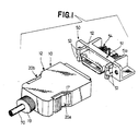
- shielded electrical cable connector 10 is electrically connectable with shielded PCB connector 50.
- Cable connector 10 includes an electrical contact assembly 27, a metal shield member 11, a dielectric cover member 12 and latch members 20a, 20b.
- Shield member 11 includes upper and lower members 11a, 11b which are stamped and formed from a suitable metal.
- the side and rear walls of lower member 11b closely fit within the side and rear walls of upper member 11a.
- Projections 15a′ extend outwardly from the side walls of lower member 11b and are disposed in rectangular openings 15b in the side walls of upper member 11a thereby latching members 11a, 11b together and forming shield member 11 having an open front end.
- L-shaped mounting members 13 extend outwardly from the side walls of member 11a between openings 15b.
- the rear walls of members 11a, 11b have semicircular sections 14a, 14b which form a cylindrical ferrule 14 through which insulated electrical conductors 71 of shielded electrical cable 70 extend and metal shield 72 of cable 70 is terminated to the outer grooved surfaces of sections 14a, 14b by the crimping of larger diameter section 16a of metal ferrule 16 thereon while smaller diameter section 16b is crimped onto outer dielectric jacket 73 of cable 70, as shown in Figure 6.
- Dielectric cover member 12 is molded from a suitable dielectric material that has stiffly-flexible characteristics. Openings 17 are located in the side walls of cover member 12 and the front end is open. An oblong section 19 having grooves18 therein projects from a rear wall of cover member 12; grooves 18 enabling section 19 to be flexible.
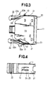
- Latch members 20a, 20b are shown in Figures 1-4 and 6 and are made of thin metal plates 21 having spring characteristics and dielectric pressing members 22.
- Spaced hook members 23 are located at the front ends of plates 21.
- U-shaped slots 24 are located in plates 21 thereby forming cantilever members 25.
- Spring members 26 are bent inwardly from the rear ends of plates 21 and the free ends thereof extend toward hook members 23.
- Pressing members 22 are molded from a suitable dielectric material and have slots 22a along which rear sections of plates 21 are press-fitted; the outer surfaces of pressing members 22 being grooved. Openings 22b are located in the bottom walls of pressing members 22 so that the spring members 26 can extend outwardly therefrom.
- Latch members 20a, 20b are mounted onto L-shaped mounting members 13 of shield member 11 by pressing cantilever members 25 against members 13 causing the cantilever members 25 to move outwardly and members 13 to move through slots 24 whereafter the latch members 20a, 20b are moved forwardly so that cantilever members 25 move back to their original positions with the short legs 13′ of members 13 constituting mounting sections which are disposed in the vertical sections 24′ of slots 24, as shown in Figures 3 and 4.
- latch members 20a, 20b are hingedly mounted on mounting members 13 of shield member 11 with long legs 13 ⁇ of members 13 maintaining the latch members 20a, 20b on members 13 and cantilever members 25 maintain legs 13′ within sections 24′ of slots 24.
- This enables latch members 20a, 20b to be easily mounted onto and to pivot about mounting members 13 when pressing members 22 are moved inwardly against the bias of spring members 26 which engage the sides of shield member 11 so that hook members 23 are moved away from the sides of the shield member 11.
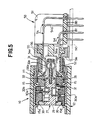
- Contact assembly 27, shown in Figures 5 and 6, includes a front dielectric housing 28, a rear dielectric housing 29 and dielectric cover members 30.
- Metal shield 31 has a profiled front section that mates with profiled section 52 of connector 50 making electrical connection therewith and a rear section that is secured onto housing 28.
- Contact sections 32a of electrical contacts 32 are disposed in passageways of housing 28 and the front ends of contact sections 32a are positioned under flanges at the front ends of the passageways thereby placing them under spring tension.
- Termination sections 32b of contacts 32 are of the known insulation displacement type and are positioned normal to contact sections 32a in housing 29 and housings 28, 29 secure contacts 32 in position.
- Cover members 30 are latchably secured onto the top and bottom of housing 29 and they have slots 30a in which the upper ends of termination sections 32b are disposed.
- Complementary PCB connector 50 as shown in Figures 1, 5, 6, 8 and 9, comprises a housing 51 which includes a metal housing 55 and a dielectric housing 56 as part of profiled section 52 which along with hook members 53 extend outwardly from a front surface 51a of housing 55.
- a front section 57 of dielectric housing 56 has a tapered recess 58 in which a tapered projection 59 at the front end of metal housing 55 is disposed thereby securing the parts of housings 55, 56 together.
- Electrical contacts 54 have contact sections 54a secured in passageways 56a of dielectric housing 56 and post sections 54b that are normal to contact sections 54a which extend through openings 81 of dielectric plate 80 to maintain post sections 54b in alignment for disposition in holes of a printed circuit board 90.
- the front ends 54′ of contacts 54 are positioned under a flange 60 at the front end of passageways 56a thereby placing contact sections 54a under spring tension.
- projections 61, 62 are located on the bottom surface of metal housing 55 for engagement with an upper surface of board 90 when connector 50 is mounted thereon so that connector 50 is spaced from such board surface to enable cleaning of the board after soldering post sections 54b and other components thereto.
- Projections 61 surround holes 63 which serve to receive mounting members, such as screws, bolts, or other known members (not shown), to secure connector 50 onto board 90.
- Cable 70 has an end stripped exposing insulated conductors 71 and shield 72 ( Figure 6).
- Cover member 12 and ferrule 16 are positioned on cable 70.
- Conductors 71 are terminated to respective termination sections 32b of contacts 32 by pressing cover members 30 inwardly to their latched positions on housing 29 thereby pressing conductors 71 into the insulation displacement slots of termination sections 32b.
- Contact assembly 27 is then positioned within low shield member 11b with front projections 15a of member 11b being disposed in a space between the housing 28 and lower cover member 30 and rear projections 15a of member 11b being positioned adjacent a rear surface of lower cover member 30.
- Upper shield member 11a has latch members 20a, 20b mounted on mounting members 13 and is latchably mounted on lower member 11b via projections 15a′ in openings 15b.
- Exposed shield 72 is positioned on ferrule section 14 and sections 16a, 16b of ferrule 16 are crimped onto ferrule section 14 and jacket 73 of cable 70.
- Cover member 12 is moved along cable 70 covering shield member 11 with pressing members 22 being disposed in openings 17 and hook members 23 being disposed just inside the open front end of cover member 12 ( Figure 6).
- Projections 15c of members 11a, 11b engage recesses (not shown) on inside surfaces of the upper and bottom walls of cover member 12 to maintain cover member 12 in position on shield member 11.
- profiled section 52 electrically fits within the profiled front section of shield 31, contact sections 32a, 54a are electrically engaged and hook members 23, 53 are hooked together thereby maintaining connectors 10, 50 securely latched together.
- Pressing pressing members 22 inwardly causes latch members 20a, 20b to pivot about mounting members 13 thereby moving hook members 23 outwardly and free of hook members 53 so that connectors 10, 50 can be disconnected.
- the electrical connector of the present invention has latch members that are of simple contsruction which an easy to assemble onto a shield member and which have displayed outstanding stability after many operations thereby assuring accurate latching and unlatching operations.
Landscapes
- Details Of Connecting Devices For Male And Female Coupling (AREA)
Applications Claiming Priority (2)
| Application Number | Priority Date | Filing Date | Title |
|---|---|---|---|
| JP176324/88 | 1988-07-15 | ||
| JP63176324A JPH0817102B2 (ja) | 1988-07-15 | 1988-07-15 | 電気コネクタ |
Publications (3)
| Publication Number | Publication Date |
|---|---|
| EP0351083A2 true EP0351083A2 (de) | 1990-01-17 |
| EP0351083A3 EP0351083A3 (en) | 1990-10-10 |
| EP0351083B1 EP0351083B1 (de) | 1994-03-16 |
Family
ID=16011595
Family Applications (1)
| Application Number | Title | Priority Date | Filing Date |
|---|---|---|---|
| EP89306364A Expired - Lifetime EP0351083B1 (de) | 1988-07-15 | 1989-06-23 | Elektrischer Steckverbinder |
Country Status (7)
| Country | Link |
|---|---|
| US (1) | US4961711A (de) |
| EP (1) | EP0351083B1 (de) |
| JP (1) | JPH0817102B2 (de) |
| KR (1) | KR940009371B1 (de) |
| CN (1) | CN1022720C (de) |
| DE (1) | DE68913839T2 (de) |
| MY (1) | MY104664A (de) |
Cited By (11)
| Publication number | Priority date | Publication date | Assignee | Title |
|---|---|---|---|---|
| DE9003014U1 (de) * | 1990-03-12 | 1991-07-11 | Grote & Hartmann Gmbh & Co Kg, 5600 Wuppertal | Elektrischer Steckverbinder mit zwei durch eine Verriegelungseinrichtung miteinander verriegelbaren Gehäusen |
| EP0462839A1 (de) * | 1990-06-21 | 1991-12-27 | ASHLEY & ROCK LIMITED | Befestigung von elektrischen Zubehörteilen |
| DE4209253C1 (de) * | 1992-03-21 | 1993-02-25 | Kabelwerke Reinshagen Gmbh, 5600 Wuppertal, De | |
| DE4209252C1 (de) * | 1992-03-21 | 1993-03-04 | Kabelwerke Reinshagen Gmbh, 5600 Wuppertal, De | |
| DE4235271C1 (de) * | 1992-10-20 | 1993-09-30 | Reinshagen Kabelwerk Gmbh | Elektrischer Stecker mit mechanischer Verriegelung |
| FR2720197A1 (fr) * | 1994-05-19 | 1995-11-24 | Whitaker Corp | Connecteur pour câble électrique. |
| EP0617482A3 (en) * | 1993-03-24 | 1996-03-20 | Kress Elektrik Gmbh & Co | Mains power supply plug. |
| EP0801447A1 (de) * | 1996-04-12 | 1997-10-15 | Framatome Connectors International | Abgeschirmter Verbinder mit Stecker und Ablagefläche ausgerüstet mit einer Ver- bzw. Entriegelungseinrichtung |
| EP0901294A3 (de) * | 1997-09-03 | 2003-12-03 | Japan Aviation Electronics Industry, Limited | Verbindungsvorrichtung, Fernbedienung dafür und Anschlussleistenrahmenstruktur |
| EP1533872A1 (de) * | 2003-11-24 | 2005-05-25 | Delphi Technologies, Inc. | Steckverbinder |
| US11454153B2 (en) * | 2018-03-08 | 2022-09-27 | Delphi Technologies Ip Limited | Electrical connector for a SCR doser |
Families Citing this family (74)
| Publication number | Priority date | Publication date | Assignee | Title |
|---|---|---|---|---|
| US5139448A (en) * | 1985-05-24 | 1992-08-18 | North American Specialties Corporation | Solder-bearing lead |
| JPH0817102B2 (ja) | 1988-07-15 | 1996-02-21 | 日本エー・エム・ピー株式会社 | 電気コネクタ |
| US4986765A (en) | 1989-02-21 | 1991-01-22 | Amp Incorporated | Insertable latch means for use in an electrical connector |
| JP2704553B2 (ja) * | 1989-09-22 | 1998-01-26 | 日本エー・エム・ピー株式会社 | エッジコネクタおよびコネクタ用基板係止装置 |
| JPH083985Y2 (ja) * | 1989-10-23 | 1996-01-31 | 富士通株式会社 | コネクタ |
| JPH0733403Y2 (ja) * | 1989-12-04 | 1995-07-31 | ホシデン株式会社 | コネクタ |
| US5096436A (en) * | 1989-12-20 | 1992-03-17 | Burndy Corporation | Method of manufacturing a cable connector assembly |
| US5021002A (en) * | 1989-12-20 | 1991-06-04 | Burndy Corporation | Snap-lock electrical connector with quick release |
| US5199897A (en) * | 1990-03-15 | 1993-04-06 | Japan Aviation Electronics Industry, Ltd. | Electrical connectors |
| JP2531414Y2 (ja) * | 1990-04-18 | 1997-04-02 | 第一電子工業株式会社 | コネクタフードヘのロック片取付構造 |
| JPH083988Y2 (ja) * | 1990-05-19 | 1996-01-31 | 富士通株式会社 | コネクタカバー |
| JP2509581Y2 (ja) * | 1990-05-29 | 1996-09-04 | 住友スリーエム株式会社 | 入出力ケ―ブルコネクタ用シェルキット |
| US5154629A (en) * | 1990-08-08 | 1992-10-13 | Icontec, Inc. | Energy transmission cable connector with latching mechanism |
| US5078623A (en) * | 1990-08-29 | 1992-01-07 | Wang Tsan Chi | Structure of passive electric connector |
| US5052948A (en) * | 1990-11-19 | 1991-10-01 | Itt Corporation | Connector ground and shield |
| JPH04184906A (ja) * | 1990-11-20 | 1992-07-01 | Mitsubishi Electric Corp | 信号ラインフイルタ用磁性体コア |
| US5197900A (en) * | 1990-12-21 | 1993-03-30 | Icontec, Inc. | Energy transmission cable connector with interchangeable locking mechanisms |
| US6541756B2 (en) * | 1991-03-21 | 2003-04-01 | Masimo Corporation | Shielded optical probe having an electrical connector |
| US5645440A (en) | 1995-10-16 | 1997-07-08 | Masimo Corporation | Patient cable connector |
| US5201669A (en) * | 1991-09-16 | 1993-04-13 | Advanced-Connectek Inc. | Connection device of a computer connection |
| US5178556A (en) * | 1991-10-24 | 1993-01-12 | Advanced-Connectek Inc. | Computer plug connector fastening mechanism |
| US5167523A (en) * | 1991-11-01 | 1992-12-01 | Harbor Electronics, Inc. | Electrical connector |
| JP2903193B2 (ja) * | 1992-02-26 | 1999-06-07 | 三菱電線工業株式会社 | コネクタのロック機構 |
| WO1993018559A1 (en) * | 1992-03-06 | 1993-09-16 | Augat Inc. | Edge card interconnection system |
| JP2595056Y2 (ja) * | 1993-01-25 | 1999-05-24 | 日本航空電子工業株式会社 | コネクタプラグ |
| US5588864A (en) * | 1994-03-11 | 1996-12-31 | Lin; Chao-Tsung | Connection device of a computer connector |
| US5486117A (en) * | 1994-08-09 | 1996-01-23 | Molex Incorporated | Locking system for an electrical connector assembly |
| USD363700S (en) | 1995-03-23 | 1995-10-31 | Symbol Technologies, Inc. | Cable assembly |
| US5580268A (en) * | 1995-03-31 | 1996-12-03 | Molex Incorporated | Lockable electrical connector |
| USD384330S (en) * | 1995-12-05 | 1997-09-30 | Hirose Electric Co., Ltd. | Electrical connector |
| US5890929A (en) * | 1996-06-19 | 1999-04-06 | Masimo Corporation | Shielded medical connector |
| US5941726A (en) * | 1996-11-27 | 1999-08-24 | The Whitaker Corporation | Interlocking release latching system for electrical connector |
| JP3417782B2 (ja) * | 1997-02-05 | 2003-06-16 | 矢崎総業株式会社 | シールド部材を有するコネクタ |
| US5899772A (en) * | 1997-02-26 | 1999-05-04 | The Whitaker Corporation | Shielding for an electrical connector |
| USD411523S (en) | 1997-08-22 | 1999-06-29 | Dazzle Multimedia | Video capture hardware |
| GB2329283A (en) * | 1997-09-12 | 1999-03-17 | Itt Mfg Enterprises Inc | Screened cable terminating ferrule |
| NO983246L (no) * | 1997-09-29 | 1999-03-30 | Siemens Ag | Kabelst°psel med jordingskontakt |
| US6149451A (en) * | 1998-06-12 | 2000-11-21 | Atl Technology, Inc. | Cable connector latching device |
| US6061584A (en) * | 1998-10-28 | 2000-05-09 | Lovejoy; David A. | Pulse oximetry sensor |
| US6231373B1 (en) * | 1998-12-21 | 2001-05-15 | Avaya Technology Corp. | Connector with integrated living hinge and resettable spring |
| US6152754A (en) * | 1999-12-21 | 2000-11-28 | Masimo Corporation | Circuit board based cable connector |
| USD448007S1 (en) | 2000-09-01 | 2001-09-18 | Hon Hai Precision Ind. Co., Ltd. | Shroud structure for a cable connector |
| USD447467S1 (en) | 2000-09-14 | 2001-09-04 | Smk Corporation | Electric connector |
| US6681458B2 (en) * | 2001-08-02 | 2004-01-27 | International Engine Intellectual Property Company, Llc | Spring clip |
| US6726501B2 (en) | 2002-06-21 | 2004-04-27 | Molex Incorporated | Latching system for electrical connectors |
| CN2567816Y (zh) * | 2002-09-03 | 2003-08-20 | 鸿富锦精密工业(深圳)有限公司 | 插头连接器 |
| US7083460B2 (en) * | 2004-08-25 | 2006-08-01 | Hon Hai Precision Ind. Co., Ltd. | Cable end connector having a latching device and an unlatching actuator |
| CN2826733Y (zh) * | 2005-03-11 | 2006-10-11 | 华为技术有限公司 | 一种连接器接口 |
| CN2792095Y (zh) * | 2005-04-14 | 2006-06-28 | 富士康(昆山)电脑接插件有限公司 | 移动存储装置 |
| US7134899B1 (en) * | 2005-11-21 | 2006-11-14 | George Ying-Liang Huang | Electrical connector assembly |
| US10188348B2 (en) | 2006-06-05 | 2019-01-29 | Masimo Corporation | Parameter upgrade system |
| US7880626B2 (en) | 2006-10-12 | 2011-02-01 | Masimo Corporation | System and method for monitoring the life of a physiological sensor |
| US7484989B2 (en) * | 2006-11-29 | 2009-02-03 | Ohio Associated Enterprises, Llc | Low friction cable assembly latch |
| CN101232136B (zh) * | 2007-01-23 | 2010-06-02 | 富士康(昆山)电脑接插件有限公司 | 电连接器 |
| US7513799B1 (en) | 2007-05-15 | 2009-04-07 | Lockheed Martin Corporation | Lightweight electrical connector split backshell |
| US7824208B2 (en) * | 2009-03-25 | 2010-11-02 | Ohio Associated Enterprises, Llc | Electrical cable connector latch mechanism |
| US8571619B2 (en) | 2009-05-20 | 2013-10-29 | Masimo Corporation | Hemoglobin display and patient treatment |
| JP2011003386A (ja) * | 2009-06-18 | 2011-01-06 | Makita Corp | 電気コードのコネクタ |
| DE102010038266B4 (de) * | 2010-10-19 | 2013-05-23 | Harting Electric Gmbh & Co. Kg | Mehrteiliges Steckverbindergehäuse |
| DE102011005385B4 (de) * | 2011-03-10 | 2022-07-14 | Te Connectivity Germany Gmbh | Verbindergehäuse für einen Verbinder, Verbinder sowie Verbindungseinrichtung |
| US9595787B2 (en) * | 2011-11-23 | 2017-03-14 | 3M Innovative Properties Company | Latching connector assembly |
| JP2014120407A (ja) * | 2012-12-19 | 2014-06-30 | D D K Ltd | 電気コネクタ |
| DE102013111506B3 (de) * | 2013-10-18 | 2015-01-08 | Phoenix Contact Gmbh & Co. Kg | Steckverbinder mit Verrastungssystem |
| JP6320158B2 (ja) * | 2014-05-12 | 2018-05-09 | タイコエレクトロニクスジャパン合同会社 | コネクタ |
| US10944155B2 (en) * | 2015-01-13 | 2021-03-09 | Commscope Technologies Llc | Standard antenna interface connector assembly |
| US10283899B2 (en) * | 2016-10-10 | 2019-05-07 | Cisco Technology, Inc. | Cable header |
| JP6708355B2 (ja) * | 2017-09-11 | 2020-06-10 | 矢崎総業株式会社 | コネクタカバー |
| US10916885B2 (en) * | 2018-04-17 | 2021-02-09 | Amphenol AssembleTech(Xiamen) Co., Ltd | High-speed connector for automobile |
| US10571640B2 (en) | 2018-06-22 | 2020-02-25 | Panduit Corp. | Cassette adapter and method of installation |
| CA190012S (en) * | 2019-03-18 | 2021-05-03 | Binatone Electronics Int Ltd | Earphones |
| US11515655B2 (en) * | 2019-04-08 | 2022-11-29 | Amphenol AssembleTech(Xiamen) Co., Ltd | High-speed connector for automobile |
| DE102020117041A1 (de) * | 2020-06-29 | 2021-12-30 | Valeo Schalter Und Sensoren Gmbh | Sensorvorrichtung zum Erfassen eines Drehens einer Welle um eine Drehachse |
| US12609485B2 (en) * | 2021-06-28 | 2026-04-21 | Molex, Llc | High power connector |
| DE102021131662A1 (de) | 2021-12-01 | 2023-06-01 | Erni International Ag | Steckverbinder mit Verriegelungssystem |
Family Cites Families (14)
| Publication number | Priority date | Publication date | Assignee | Title |
|---|---|---|---|---|
| GB773619A (en) * | 1954-08-13 | 1957-05-01 | Horatio Henry Burtt | Locking mechanism for electrical plug and socket connectors |
| US3329925A (en) * | 1965-07-29 | 1967-07-04 | Leeds & Northrup Co | Interlocking shielded connector |
| DE2708998A1 (de) * | 1977-03-02 | 1978-09-07 | Licentia Gmbh | Steckbaugruppe zum einschub in einen baugruppentraeger |
| JPH0249659Y2 (de) * | 1985-04-17 | 1990-12-27 | ||
| US4621885A (en) * | 1985-09-20 | 1986-11-11 | Amp Incorporated | Ribbon cable connector with improved cover latch |
| JPH0429513Y2 (de) * | 1985-11-28 | 1992-07-16 | ||
| JPS63155572A (ja) * | 1986-12-12 | 1988-06-28 | アンプ インコ−ポレ−テツド | シ−ルドコネクタ |
| US4762505A (en) * | 1987-04-16 | 1988-08-09 | Amp Incorporated | Positive retention connector latch |
| US4735583A (en) * | 1987-04-24 | 1988-04-05 | Amp Incorporated | Spring latch for latching together electrical connectors and improved latching system |
| JPH0345420Y2 (de) * | 1987-04-30 | 1991-09-25 | ||
| US4822303A (en) * | 1987-05-18 | 1989-04-18 | Hirose Electric Co., Ltd. | Electrical connector |
| JP2787307B2 (ja) * | 1987-07-17 | 1998-08-13 | アンプ インコーポレーテッド | コネクタ |
| JPH0817102B2 (ja) | 1988-07-15 | 1996-02-21 | 日本エー・エム・ピー株式会社 | 電気コネクタ |
| US4842542A (en) * | 1988-12-07 | 1989-06-27 | Amp Incorporated | Connector with removable latch block and removable latch block therefor |
-
1988
- 1988-07-15 JP JP63176324A patent/JPH0817102B2/ja not_active Expired - Lifetime
-
1989
- 1989-06-14 US US07/366,062 patent/US4961711A/en not_active Expired - Lifetime
- 1989-06-17 MY MYPI89000820A patent/MY104664A/en unknown
- 1989-06-23 DE DE68913839T patent/DE68913839T2/de not_active Expired - Fee Related
- 1989-06-23 EP EP89306364A patent/EP0351083B1/de not_active Expired - Lifetime
- 1989-07-07 KR KR1019890009649A patent/KR940009371B1/ko not_active Expired - Fee Related
- 1989-07-14 CN CN89104910A patent/CN1022720C/zh not_active Expired - Fee Related
Cited By (14)
| Publication number | Priority date | Publication date | Assignee | Title |
|---|---|---|---|---|
| DE9003014U1 (de) * | 1990-03-12 | 1991-07-11 | Grote & Hartmann Gmbh & Co Kg, 5600 Wuppertal | Elektrischer Steckverbinder mit zwei durch eine Verriegelungseinrichtung miteinander verriegelbaren Gehäusen |
| EP0462839A1 (de) * | 1990-06-21 | 1991-12-27 | ASHLEY & ROCK LIMITED | Befestigung von elektrischen Zubehörteilen |
| DE4209253C1 (de) * | 1992-03-21 | 1993-02-25 | Kabelwerke Reinshagen Gmbh, 5600 Wuppertal, De | |
| DE4209252C1 (de) * | 1992-03-21 | 1993-03-04 | Kabelwerke Reinshagen Gmbh, 5600 Wuppertal, De | |
| EP0562350A1 (de) * | 1992-03-21 | 1993-09-29 | Delphi Automotive Systems Deutschland GmbH | Elektrischer Stecker mit einer mechanischen Verriegelung mit Hilfe einer Rastfeder und einer Lösetaste |
| DE4235271C1 (de) * | 1992-10-20 | 1993-09-30 | Reinshagen Kabelwerk Gmbh | Elektrischer Stecker mit mechanischer Verriegelung |
| EP0617482A3 (en) * | 1993-03-24 | 1996-03-20 | Kress Elektrik Gmbh & Co | Mains power supply plug. |
| FR2720197A1 (fr) * | 1994-05-19 | 1995-11-24 | Whitaker Corp | Connecteur pour câble électrique. |
| EP0801447A1 (de) * | 1996-04-12 | 1997-10-15 | Framatome Connectors International | Abgeschirmter Verbinder mit Stecker und Ablagefläche ausgerüstet mit einer Ver- bzw. Entriegelungseinrichtung |
| FR2747518A1 (fr) * | 1996-04-12 | 1997-10-17 | Framatome Connectors France | Connecteur blinde du type comprenant une fiche et une embase et muni d'un organe de verrouillage/deverrouillage |
| US5879194A (en) * | 1996-04-12 | 1999-03-09 | Framatome Connectors International | Shielded connector of the type comprising a plug and a socket and provided with a locking/unlocking component |
| EP0901294A3 (de) * | 1997-09-03 | 2003-12-03 | Japan Aviation Electronics Industry, Limited | Verbindungsvorrichtung, Fernbedienung dafür und Anschlussleistenrahmenstruktur |
| EP1533872A1 (de) * | 2003-11-24 | 2005-05-25 | Delphi Technologies, Inc. | Steckverbinder |
| US11454153B2 (en) * | 2018-03-08 | 2022-09-27 | Delphi Technologies Ip Limited | Electrical connector for a SCR doser |
Also Published As
| Publication number | Publication date |
|---|---|
| JPH0227674A (ja) | 1990-01-30 |
| KR900002500A (ko) | 1990-02-28 |
| CN1022720C (zh) | 1993-11-10 |
| JPH0817102B2 (ja) | 1996-02-21 |
| CN1039508A (zh) | 1990-02-07 |
| EP0351083B1 (de) | 1994-03-16 |
| EP0351083A3 (en) | 1990-10-10 |
| MY104664A (en) | 1994-05-31 |
| KR940009371B1 (ko) | 1994-10-07 |
| DE68913839T2 (de) | 1994-10-06 |
| DE68913839D1 (de) | 1994-04-21 |
| US4961711A (en) | 1990-10-09 |
Similar Documents
| Publication | Publication Date | Title |
|---|---|---|
| US4961711A (en) | Electrical connector | |
| US5460533A (en) | Cable backpanel interconnection | |
| US5125854A (en) | Modular electrical connector | |
| EP0118168B2 (de) | Elektrischer Steckverbinder und Steckdose dafür | |
| US6217364B1 (en) | Electrical connector assembly with guide pin latching system | |
| US5213534A (en) | Electrical connector assembly for flat flexible cable | |
| US4941849A (en) | Shielded electrical connector having an insulating cover on the shielding member | |
| US5118306A (en) | Multi-conductor electrical connector | |
| JP2602473B2 (ja) | プラグ・ソケット型電気コネクタ | |
| CN109845047B (zh) | 连接器结构 | |
| EP0928046A1 (de) | Abgeschirmte elektrische Verbinderanordnung | |
| EP0583934A2 (de) | Hochfrequenzkabelverbinder | |
| US4491381A (en) | Electrical panelboard connector | |
| US5415566A (en) | Shielded electrical connector assembly | |
| US5482477A (en) | Micro-miniature coaxial connector with positive locking member | |
| JP2005527959A (ja) | 改良されたレセプタクル | |
| US20070037450A1 (en) | Cable connector assmbly with holder | |
| EP0873581B1 (de) | Elektrische steckvorrichtung | |
| JP3104176B2 (ja) | 同軸ケーブル用の電気コネクタ | |
| KR100204373B1 (ko) | 편평 케이블을 회로 기판에 상호 접속시키기 위한 전기커넥터 조립체 | |
| KR100198409B1 (ko) | 자체 로킹 결합 단자 구조 | |
| JP2005535069A (ja) | 電気コネクタ用ラッチシステム | |
| IL106494A (en) | Shielded data connector | |
| JP3057562B2 (ja) | 電気コネクタのキー機構 | |
| US20060110969A1 (en) | Cable assembly having improved latch |
Legal Events
| Date | Code | Title | Description |
|---|---|---|---|
| PUAI | Public reference made under article 153(3) epc to a published international application that has entered the european phase |
Free format text: ORIGINAL CODE: 0009012 |
|
| AK | Designated contracting states |
Kind code of ref document: A2 Designated state(s): DE FR GB IT NL |
|
| PUAL | Search report despatched |
Free format text: ORIGINAL CODE: 0009013 |
|
| AK | Designated contracting states |
Kind code of ref document: A3 Designated state(s): DE FR GB IT NL |
|
| 17P | Request for examination filed |
Effective date: 19901227 |
|
| 17Q | First examination report despatched |
Effective date: 19921204 |
|
| RAP1 | Party data changed (applicant data changed or rights of an application transferred) |
Owner name: THE WHITAKER CORPORATION |
|
| GRAA | (expected) grant |
Free format text: ORIGINAL CODE: 0009210 |
|
| AK | Designated contracting states |
Kind code of ref document: B1 Designated state(s): DE FR GB IT NL |
|
| REF | Corresponds to: |
Ref document number: 68913839 Country of ref document: DE Date of ref document: 19940421 |
|
| ET | Fr: translation filed | ||
| ITF | It: translation for a ep patent filed | ||
| PLBE | No opposition filed within time limit |
Free format text: ORIGINAL CODE: 0009261 |
|
| STAA | Information on the status of an ep patent application or granted ep patent |
Free format text: STATUS: NO OPPOSITION FILED WITHIN TIME LIMIT |
|
| 26N | No opposition filed | ||
| REG | Reference to a national code |
Ref country code: GB Ref legal event code: IF02 |
|
| PGFP | Annual fee paid to national office [announced via postgrant information from national office to epo] |
Ref country code: NL Payment date: 20020325 Year of fee payment: 14 |
|
| PGFP | Annual fee paid to national office [announced via postgrant information from national office to epo] |
Ref country code: FR Payment date: 20020605 Year of fee payment: 14 |
|
| PGFP | Annual fee paid to national office [announced via postgrant information from national office to epo] |
Ref country code: DE Payment date: 20020628 Year of fee payment: 14 |
|
| PG25 | Lapsed in a contracting state [announced via postgrant information from national office to epo] |
Ref country code: DE Free format text: LAPSE BECAUSE OF NON-PAYMENT OF DUE FEES Effective date: 20040101 Ref country code: NL Free format text: LAPSE BECAUSE OF NON-PAYMENT OF DUE FEES Effective date: 20040101 |
|
| PG25 | Lapsed in a contracting state [announced via postgrant information from national office to epo] |
Ref country code: FR Free format text: LAPSE BECAUSE OF NON-PAYMENT OF DUE FEES Effective date: 20040227 |
|
| NLV4 | Nl: lapsed or anulled due to non-payment of the annual fee |
Effective date: 20040101 |
|
| REG | Reference to a national code |
Ref country code: FR Ref legal event code: ST |
|
| PG25 | Lapsed in a contracting state [announced via postgrant information from national office to epo] |
Ref country code: IT Free format text: LAPSE BECAUSE OF NON-PAYMENT OF DUE FEES;WARNING: LAPSES OF ITALIAN PATENTS WITH EFFECTIVE DATE BEFORE 2007 MAY HAVE OCCURRED AT ANY TIME BEFORE 2007. THE CORRECT EFFECTIVE DATE MAY BE DIFFERENT FROM THE ONE RECORDED. Effective date: 20050623 |
|
| PGFP | Annual fee paid to national office [announced via postgrant information from national office to epo] |
Ref country code: GB Payment date: 20070628 Year of fee payment: 19 |
|
| GBPC | Gb: european patent ceased through non-payment of renewal fee |
Effective date: 20080623 |
|
| PG25 | Lapsed in a contracting state [announced via postgrant information from national office to epo] |
Ref country code: GB Free format text: LAPSE BECAUSE OF NON-PAYMENT OF DUE FEES Effective date: 20080623 |