EP0351089A2 - Auswischmechanismus für Kartenabtaster - Google Patents
Auswischmechanismus für Kartenabtaster Download PDFInfo
- Publication number
- EP0351089A2 EP0351089A2 EP89306502A EP89306502A EP0351089A2 EP 0351089 A2 EP0351089 A2 EP 0351089A2 EP 89306502 A EP89306502 A EP 89306502A EP 89306502 A EP89306502 A EP 89306502A EP 0351089 A2 EP0351089 A2 EP 0351089A2
- Authority
- EP
- European Patent Office
- Prior art keywords
- card
- magnet
- crank
- drive means
- card reader
- Prior art date
- Legal status (The legal status is an assumption and is not a legal conclusion. Google has not performed a legal analysis and makes no representation as to the accuracy of the status listed.)
- Granted
Links
Images



Classifications
-
- G—PHYSICS
- G07—CHECKING-DEVICES
- G07F—COIN-FREED OR LIKE APPARATUS
- G07F7/00—Mechanisms actuated by objects other than coins to free or to actuate vending, hiring, coin or paper currency dispensing or refunding apparatus
- G07F7/02—Mechanisms actuated by objects other than coins to free or to actuate vending, hiring, coin or paper currency dispensing or refunding apparatus by keys or other credit registering devices
-
- G—PHYSICS
- G06—COMPUTING OR CALCULATING; COUNTING
- G06K—GRAPHICAL DATA READING; PRESENTATION OF DATA; RECORD CARRIERS; HANDLING RECORD CARRIERS
- G06K1/00—Methods or arrangements for marking the record carrier in digital fashion
- G06K1/12—Methods or arrangements for marking the record carrier in digital fashion otherwise than by punching
-
- G—PHYSICS
- G06—COMPUTING OR CALCULATING; COUNTING
- G06K—GRAPHICAL DATA READING; PRESENTATION OF DATA; RECORD CARRIERS; HANDLING RECORD CARRIERS
- G06K1/00—Methods or arrangements for marking the record carrier in digital fashion
- G06K1/12—Methods or arrangements for marking the record carrier in digital fashion otherwise than by punching
- G06K1/125—Methods or arrangements for marking the record carrier in digital fashion otherwise than by punching by magnetic means
-
- G—PHYSICS
- G06—COMPUTING OR CALCULATING; COUNTING
- G06K—GRAPHICAL DATA READING; PRESENTATION OF DATA; RECORD CARRIERS; HANDLING RECORD CARRIERS
- G06K13/00—Conveying record carriers from one station to another, e.g. from stack to punching mechanism
- G06K13/02—Conveying record carriers from one station to another, e.g. from stack to punching mechanism the record carrier having longitudinal dimension comparable with transverse dimension, e.g. punched card
- G06K13/08—Feeding or discharging cards
-
- G—PHYSICS
- G06—COMPUTING OR CALCULATING; COUNTING
- G06Q—INFORMATION AND COMMUNICATION TECHNOLOGY [ICT] SPECIALLY ADAPTED FOR ADMINISTRATIVE, COMMERCIAL, FINANCIAL, MANAGERIAL OR SUPERVISORY PURPOSES; SYSTEMS OR METHODS SPECIALLY ADAPTED FOR ADMINISTRATIVE, COMMERCIAL, FINANCIAL, MANAGERIAL OR SUPERVISORY PURPOSES, NOT OTHERWISE PROVIDED FOR
- G06Q20/00—Payment architectures, schemes or protocols
- G06Q20/30—Payment architectures, schemes or protocols characterised by the use of specific devices or networks
- G06Q20/34—Payment architectures, schemes or protocols characterised by the use of specific devices or networks using cards, e.g. integrated circuit [IC] cards or magnetic cards
- G06Q20/343—Cards including a counter
- G06Q20/3437—Cards including a counter the counter having non-monetary units, e.g. trips
-
- G—PHYSICS
- G07—CHECKING-DEVICES
- G07F—COIN-FREED OR LIKE APPARATUS
- G07F17/00—Coin-freed apparatus for hiring articles; Coin-freed facilities or services
- G07F17/0014—Coin-freed apparatus for hiring articles; Coin-freed facilities or services for vending, access and use of specific services not covered anywhere else in G07F17/00
Definitions
- This invention concerns card readers and in particular an erasure mechanism for erasing magnetic information stored on a card after the card has been read.
- Plastic cards bearing a magnetisable stripe are known.
- Information in the form of differentially magnetised zones of the magnetic stripe can be written using a magnetic write head and can be read by a read head provided there is relative movement between the card and the head.
- the card is one which signifies pre-payment of a service or facility such as electricity or gas
- a card reader will normally include a reading head and hitherto, adjacent the reading head has been located an erase head comprising an electro-magnet, current for which has been derived from an appropriate control circuit which is triggered to provide the erasure current as soon as the information derived from the read head has been indicated as satisfactory by logic circuitry associated with the reading head.
- an erase head comprising an electro-magnet, current for which has been derived from an appropriate control circuit which is triggered to provide the erasure current as soon as the information derived from the read head has been indicated as satisfactory by logic circuitry associated with the reading head.
- the current requirements for an erase head and the time required for the current to flow make quite significant demands on the power supply for the unit and in addition, since the current for the erase head is controlled by a processor, the latter cannot be turned off until after the card has been detected as having been removed from the card reader. Again this makes considerable demands on the power supply requirements for the card reader.
- a permanent magnet is mounted for movement towards and away from position occupied by a card in a card reader, and means is provided responsive to a satisfactory reading of the card to bring the magnet into close proximity or engagement with the region of the card on which magnetically readable information is stored, so as to corrupt and/or erase the magnetically stored information on the card.
- the magnet is carried at the end of an arm which is pivotable to allow the remote end of the arm to move in a direction towards and away from the plane of a card when located in the reader, and a drive is provided for moving the arm, from a position where it is remote from the card to a position in which the magnet is in close proximity to or touching the card, before the card is removed from the reader.
- the drive means may comprise an electric motor or a solenoid.
- the drive for moving the magnet towards the card may to an advantage be derived from the drive associated with the perforating mechanism.
- a rigid mechanical link may be provided from a drive point on the crank to a drive point associated with the mechanism for moving the magnet bearing arm towards and away from the card.
- rotation of the motor will produce appropriate movement of the magnet and by appropriate choice of the position on the crank for the point of attachment of the rigid link, so the magnet can be brought down into close proximity or contact with the card at the same time as the teeth are brought into contact with the underside of the card, to begin perforation and marking of the card.
- the card perforating mechanism is conveniently such as is described in our co-pending British Patent Application No. 2134682.
- the arm to which the magnet is attached is conveniently of resiliently deformable material and is itself attached to a yoke which is pivotable about a mounting on the card reader with the axis of pivoting of the yoke approximately parallel to the plane of the card when inserted, and a relatively rigid arm extends from the yoke separate from the arm carrying the magnet, and drive means for moving the yoke (and therefore the magnet into contact with the card), acts on the relatively rigid arm extending from the yoke.
- the drive means for the yoke will tend to move the magnet beyond the position at which it will normally be expected to engage the surface of the card, the resilience in the arm carrying the magnet will accommodate any over travel and simply increase the force exerted between the magnet and the card.
- spring means is provided for restoring the position of the magnet to a position which is well clear of not only the surface of the card but also any read head provided to read information on cards inserted into the reader.
- the spring means acts on the yoke or on a rigid extension to the yoke.
- a torsion or helical spring may be provided, associated with a pivoting of the arm carrying the magnet.
- the read head is mounted directly on a printed circuit board which itself forms part of the card reader and is mounted generally parallel to the plane which is occupied by a card when the latter is inserted in the reader, and adjacent the read head, the printed circuit board is cut away, to enable a magnet to pass through the board for making contact with a card if the latter is located below the printed circuit board.
- the magnet is carried by an arm which itself is pivotally mounted on the printed circuit board.
- the read head is mounted at the end of a finger of printed circuit board material which is separated from the remainder of the board except at the end of the finger which is remote from the end to which the reading head is attached.
- the read head will, like the magnet, be resiliently mounted relative to the remainder of the board and therefore capable of accommodating different thicknesses of card etc.
- the read head surface which is to make contact with the card normally protrudes slightly beyond the plane which will be occupied by the surface of the card which is to engage the head when the latter is inserted in the reader and by providing an appropriately curved underside surface to the read head so that on insertion of the card, the leading edge will cause the read head to be raised slightly to allow the rest of the card to pass below the read head, so a degree of pressure can be exerted between the read head and the card by the natural resilience of the finger to which the read head is attached.
- Electrical connections to the read head are conveniently formed by means of tracks formed on or in the printed circuit board material forming the finger to which the read head is itself attached.
- this characteristic can be incorporated in the improved card reader to provide the restoring force which acts on the drive means for the magnet.
- a return spring can be formed by causing the arm to which the magnet is attached (or drive means for the arm) to engage the the resiliently displaceable finger of printed circuit board material, to displace the latter out of the plane of the printed circuit board as the magnet is moved into its card engaging position.
- crank can rotate into a position at which the point of attachment of the rigid link between the crank and the drive to the magnet bearing arm is on the same side of the axis of rotation of the crank as are the teeth which, on rotation of the crank are brought into contact with the underside of the card, so the crank and magnet will be held in a position of stable equilibrium with the teeth just engaging the underside of the card and the magnet in contact with the surface of the card, until the card is pulled out of the card reader slot into which it is previously been inserted.
- a short rigid finger engaging lug extends perpendicularly from the yoke or rigid arm extending from the yoke, and this lug is arranged to engage the printed circuit board material finger providing the resilient restoring force.
- the magnet can be maintained in contact with the card during withdrawal of the card for any desired period of time depending on the amount of overtravel which is accommodated by the natural resilience of the arm carrying the magnet.
- the magnet is kept in close proximity to or actually in contact with the card during a rotation of approximately 30°C of the crank carrying the perforating teeth.
- the card reader includes a socket into which a card can be inserted and the socket is itself formed by two plastics moulded parts.
- An electric motor for driving the crank may be carried by one of the moulded parts and the printed circuit board and magnet mounting and drive mechanism are carried by the other part.
- the rigid link between the magnet driving mechanism and the crank are frequently detachable to allow the two modelled parts to be assembled or separated, the crank being fitted after assembly or removed before separation.
- the drive motor includes regions of reduced diameter at opposite ends of its housing and the moulded part to which the motor is to be attached includes two resiliently deformable yokes which can be fitted over the reduced diameter end regions of the motor to hold the motor against the moulding and secure it in place.
- Such a method of mounting obviates the need for screws or rivets.
- a sufficienlty strong permanent magnet is employed that it is only necessary to bring the magnet into close proximity to the magnetic stripe on the card to cause corruption of the data carried by the stripe. In this way it is not essential to produce relative movement between the card and the magnet to effect corruption and erasure. This is important since otherwise it might be possible for an unscrupulous customer to attempt to prevent erasure by inserting a thin separating element between the magnet and the card before the latter is removed.
- a sequence of reading and erasing a card compises the steps of:-
- Figure 1 of the drawings illustrates part of a card reader mechanism which is formed from two plastics mouldings which when fitted together form inter alia a parallel slot into which a card 10 can be inserted and which carry a printed circuit board 12 on one side and an electric motor 14 on the other side.
- the motor has an output shaft 16 on which is mounted a crank 18 having metal teeth 20 carried at the far end of the crank and which when rotated by the motor to engage the underside of a card, will perforate the latter as the card is withdrawn from the slot.
- the printed circuit board is cut away to define two resilient fingers one of which can be seen at 22 and carries on its underside a reading head 24, and the other of which can be seen at 26 and which serves as a return spring for a magnet operating mechanism to be described.
- the card includes a strip of magnetisable material 28 which can be differentially magnetised to produce a magnetic pattern which can be read by the read head 24 as the card is moved relative to the head.
- a strip of magnetisable material 28 which can be differentially magnetised to produce a magnetic pattern which can be read by the read head 24 as the card is moved relative to the head.
- induced currents in the reading head as the differentially magnetised regions of the stripe move relative to the head.
- These induced currents can be converted into voltages and amplified in known manner to provide electrical signals for processing.
- the card reader is of the type in which, after being read satisfactorily, the magnetic information is to be erased so that the card cannot be used again.
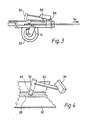
- a small powerful permanent magnet which is best seen in Figure 4 and is designated by referenece numeral 30 is carried at the lower end of a cylindrical housing 32 carried at the free end of a resiliently deformable arm 34 of plastics material possessing a high degree of springiness.
- the arm 34 extends from and is secured to the centre of a yoke 36 the ends of which straddle a mounting block 38, and is pivotable relative thereto about an axis parallel to the plane of the printed circuit board 12.
- the block 38 is in fact mounted on the printed circuit board.
- the yoke is extended to form a rigid operating arm 40 the outboard end of which includes a pin 42.
- the pin provides a mounting for a sleeve 44 which is attached to one end of a rigid connecting rod 46 the other end of which includes a similar sleeve 48 for pivotally mounting on a pin 50 which extends from the crank 18.
- the crank is connected to the end of the rigid arm 40 so that rotation of the crank will produce pivotal movement of the arm 40 and therefore the yoke 36. This in turn will produce a pivoting movement of the arm 34 and therefore a raising or lowering of the magnet.
- the restoring force provided by the finger of printed circuit board material 26 acts through a pin or lug 56 which extends from the underside of the rigid arm 40.
- the axis about which the yoke 36 rotates can be seen at 58 in Figures 2 and 3.
- the motor is held in position by means of two modelled plastics yokes which extend from the underside of the lower housing part 60.
- One of these U-shaped yokes can be seen at 62 in Figures 1, 2 and 3.
- the other U-shaped yoke holding the motor in position can be seen in Figure 10 and is designated by reference numeral 64.
- Electrical connections to the read head are conveniently formed by tracks such as 66 and 68 on the finger of printed circuit board material 22 on which the read head is mounted.
- Figure 6 is a plan view of the card 10 where the magnetic stripe 28 has had information stored therein in a magnetically readable form. This comprises a number of discreet and small locally magnetised regions which can be revealed by spreading a thin layer of black magnetic powder over the magnetic stripe and then shaking the powder off the stripe, leaving black powder adhering to the regions which have been strongly and locally magnetically orientated.
- reference numeral 74 One of these local regions is denoted by reference numeral 74.
- Figure 7 shows a card which has been said so that after dusting with black magnetic dust it does not reveal the appearance of any information such as 74 as in Figure 7.
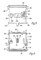
- FIGS 8 and 9 show the two parts which fit together to form the slot into which the card can slide.
- the two parts contain lugs at 76 and 78, 80 and 82 under which co-operating lugs 84, 86, 88 and 90 can slide.
- the two curved edges of the two parts at 92 and 94 co-operate to form a flared entrance to the slot.
- the read head 24 can be seen through a window 98 in the component part 100 whilst the crank 18 and teeth 20 can be seen through a slot-like window 102, in the other component part 104.
- An upstanding platform 106 ensures good contact between the card and the read head 24 and a similar upstanding platform 108 ensures that the card is flattened against a circular window 110 through which can be seen a light emitting diode 112 and a light sensitive junction 114.
- the latter are positioned so that when a white card has been inserted into the slot so that the window 110 is covered by white material, sufficient light from the light emitting diode is reflected onto the light sensitive junction to allow an electrical signal to be generated indicating the presence of the card in the slot. This signal is used to designate when the read head is to be rendered operable. If the signals from the read head are satisfactory, current is then supplied to the motor 40 to rotate the crank 18, in the manner as aforesaid.
- the teeth 20 are preferably formed from sheet metal such as brass.
- the yoke 36 and arm 34 and housing 32 are also moulded integrally from plastics material as is also the link 46 and sleeves 44 and 48.
- window 98 permits the underside of the magnet 30 and surrounding housing 32 to just be seen in the elevated position in which the magnet is well clear from the card and the read head 24, ie the position shown in Figure 1.
Landscapes
- Physics & Mathematics (AREA)
- General Physics & Mathematics (AREA)
- Engineering & Computer Science (AREA)
- Theoretical Computer Science (AREA)
- Business, Economics & Management (AREA)
- Microelectronics & Electronic Packaging (AREA)
- Computer Networks & Wireless Communication (AREA)
- Accounting & Taxation (AREA)
- Strategic Management (AREA)
- General Business, Economics & Management (AREA)
- Conveying Record Carriers (AREA)
- Control Of Vending Devices And Auxiliary Devices For Vending Devices (AREA)
Applications Claiming Priority (2)
| Application Number | Priority Date | Filing Date | Title |
|---|---|---|---|
| GB8816511A GB2220776B (en) | 1988-07-12 | 1988-07-12 | Erasure mechanism for card readers |
| GB8816511 | 1988-12-07 |
Publications (3)
| Publication Number | Publication Date |
|---|---|
| EP0351089A2 true EP0351089A2 (de) | 1990-01-17 |
| EP0351089A3 EP0351089A3 (de) | 1991-10-16 |
| EP0351089B1 EP0351089B1 (de) | 1994-02-23 |
Family
ID=10640273
Family Applications (1)
| Application Number | Title | Priority Date | Filing Date |
|---|---|---|---|
| EP89306502A Expired - Lifetime EP0351089B1 (de) | 1988-07-12 | 1989-06-27 | Auswischmechanismus für Kartenabtaster |
Country Status (6)
| Country | Link |
|---|---|
| US (1) | US5061842A (de) |
| EP (1) | EP0351089B1 (de) |
| AU (1) | AU614156B2 (de) |
| DE (1) | DE68913240T2 (de) |
| GB (1) | GB2220776B (de) |
| ZA (1) | ZA894953B (de) |
Cited By (5)
| Publication number | Priority date | Publication date | Assignee | Title |
|---|---|---|---|---|
| FR2674053A1 (fr) * | 1991-03-12 | 1992-09-18 | Dassault Electronique | Installation pour la securisation de titres de transport, en particulier a piste magnetique. |
| CH682775A5 (fr) * | 1990-03-23 | 1993-11-15 | Landis & Gyr Communications Su | Lecteur de carte. |
| EP0779599A3 (de) * | 1995-12-14 | 1998-11-04 | Ncr International Inc. | Kartenlesesystem |
| WO2001037198A1 (en) * | 1999-11-17 | 2001-05-25 | Siemens Metering Limited | Card-marking devices |
| EP1035495A3 (de) * | 1999-03-08 | 2003-01-08 | Matsushita Electric Industrial Co., Ltd. | Ic-Kartenleser |
Families Citing this family (8)
| Publication number | Priority date | Publication date | Assignee | Title |
|---|---|---|---|---|
| GB9014362D0 (en) * | 1990-06-28 | 1990-08-22 | Ampy Automation Digilog | Card reader |
| JPH05217030A (ja) * | 1991-08-07 | 1993-08-27 | Ricoh Co Ltd | カード処理方法 |
| US5834756A (en) * | 1996-06-03 | 1998-11-10 | Motorola, Inc. | Magnetically communicative card |
| DE19642246A1 (de) * | 1996-10-12 | 1998-04-16 | Basf Ag | Verfahren zur Herstellung einer stabilen Dispersion von Melamin in Polyolkomponenten |
| US5905252A (en) * | 1997-11-24 | 1999-05-18 | Itt Manufacturing Enterprises, Inc. | Card gate mechanism |
| DE19828792C2 (de) | 1998-06-27 | 2001-05-03 | Ernst Reiner Gmbh & Co Kg Fein | Vorrichtung zum Abtrennen eines Chips von einer einen Magnetstreifen aufweisenden Chipkarte |
| JP2002083269A (ja) * | 2000-09-11 | 2002-03-22 | Matsushita Electric Ind Co Ltd | カードリーダ |
| FR2887357A1 (fr) | 2005-06-20 | 2006-12-22 | Gemplus Sa | Procede de fabrication d'un objet electronique comportant une etape de transfert de donnees et objet obtenu |
Family Cites Families (10)
| Publication number | Priority date | Publication date | Assignee | Title |
|---|---|---|---|---|
| DE1925128B1 (de) * | 1969-05-16 | 1970-11-19 | Sued Atlas Werke Gmbh | Loeschvorrichtung fuer Aufzeichnungstraeger von Magnettongeraeten |
| US3836753A (en) * | 1971-12-05 | 1974-09-17 | Amp Inc | Magnetic card reader |
| FR2219729A5 (de) * | 1973-02-23 | 1974-09-20 | Crouzet Sa | |
| GB1593377A (en) * | 1976-12-10 | 1981-07-15 | Emi Ltd | Security document and system |
| WO1981003562A1 (en) * | 1980-06-03 | 1981-12-10 | K Payne | Debit card system |
| ZA829559B (en) * | 1982-01-29 | 1983-10-26 | Hawker Siddeley Revenue Contr | Read and erase device |
| GB2134682B (en) * | 1983-01-29 | 1986-03-05 | Ampy Automation Digilog | Methods and apparatus for marking cards |
| DE3337845A1 (de) * | 1983-10-18 | 1985-04-25 | Nixdorf Computer Ag, 4790 Paderborn | Festplattenlaufwerk |
| US4711993A (en) * | 1984-01-05 | 1987-12-08 | Kosednar Joseph F | Fraud-resistant manual magnetic reader-writer system for debit card use |
| IT1185231B (it) * | 1985-07-11 | 1987-11-04 | Ages Spa | Testa di lettura e di obliterazione particolarmente per tessere magnetiche |
-
1988
- 1988-07-12 GB GB8816511A patent/GB2220776B/en not_active Expired - Lifetime
-
1989
- 1989-06-27 EP EP89306502A patent/EP0351089B1/de not_active Expired - Lifetime
- 1989-06-27 DE DE68913240T patent/DE68913240T2/de not_active Expired - Fee Related
- 1989-06-29 ZA ZA894953A patent/ZA894953B/xx unknown
- 1989-07-03 US US07/374,754 patent/US5061842A/en not_active Expired - Fee Related
- 1989-07-03 AU AU37280/89A patent/AU614156B2/en not_active Ceased
Cited By (5)
| Publication number | Priority date | Publication date | Assignee | Title |
|---|---|---|---|---|
| CH682775A5 (fr) * | 1990-03-23 | 1993-11-15 | Landis & Gyr Communications Su | Lecteur de carte. |
| FR2674053A1 (fr) * | 1991-03-12 | 1992-09-18 | Dassault Electronique | Installation pour la securisation de titres de transport, en particulier a piste magnetique. |
| EP0779599A3 (de) * | 1995-12-14 | 1998-11-04 | Ncr International Inc. | Kartenlesesystem |
| EP1035495A3 (de) * | 1999-03-08 | 2003-01-08 | Matsushita Electric Industrial Co., Ltd. | Ic-Kartenleser |
| WO2001037198A1 (en) * | 1999-11-17 | 2001-05-25 | Siemens Metering Limited | Card-marking devices |
Also Published As
| Publication number | Publication date |
|---|---|
| GB8816511D0 (en) | 1988-08-17 |
| ZA894953B (en) | 1990-06-27 |
| AU614156B2 (en) | 1991-08-22 |
| GB2220776A (en) | 1990-01-17 |
| DE68913240D1 (de) | 1994-03-31 |
| EP0351089B1 (de) | 1994-02-23 |
| EP0351089A3 (de) | 1991-10-16 |
| AU3728089A (en) | 1990-01-18 |
| US5061842A (en) | 1991-10-29 |
| GB2220776B (en) | 1992-04-08 |
| DE68913240T2 (de) | 1994-06-01 |
Similar Documents
| Publication | Publication Date | Title |
|---|---|---|
| US5061842A (en) | Erasure mechanism for card readers | |
| EP0131410B1 (de) | Vorrichtung zum Lesen und Einschreiben einer externen integrierten Schaltungsspeicherkarte | |
| CA1204509A (en) | Data reading device for data processing apparatus | |
| US5780827A (en) | Landing contact mechanism and card latch for smart card reader/writer | |
| JP3078227U (ja) | Icカードコネクタ | |
| EP0727758A1 (de) | Chipkartenleser | |
| JPH0896089A (ja) | Icカード情報処理装置 | |
| EP0309193A2 (de) | Kartenleser | |
| JP3815325B2 (ja) | Icカードリーダ | |
| EP0911757A2 (de) | Adapter für Plattenkassetten | |
| GB2214680A (en) | Card reader | |
| JP2593143B2 (ja) | Icカードリーダーライター | |
| JP2625659B2 (ja) | Icカードリーダーライター | |
| JP2824268B2 (ja) | 電子機器 | |
| JPH11250195A (ja) | スマートカードリーダ | |
| JPH07182245A (ja) | メモリカード | |
| JP3013020U (ja) | プリペイドカード挿入検出機構 | |
| JP2933753B2 (ja) | メモリカードリーダライタ | |
| JP3013021U (ja) | プリペイドカード挿入検出機構 | |
| JPH08235327A (ja) | Icカードリーダーライター | |
| JPH0542531Y2 (de) | ||
| JPH0726771Y2 (ja) | 電子機器 | |
| JP3013019U (ja) | プリペイドカード挿入検出機構 | |
| ATE487989T1 (de) | Lese-/schreibaggregat für datenkarten | |
| JPH0935008A (ja) | チップカード用読取り装置 |
Legal Events
| Date | Code | Title | Description |
|---|---|---|---|
| PUAI | Public reference made under article 153(3) epc to a published international application that has entered the european phase |
Free format text: ORIGINAL CODE: 0009012 |
|
| AK | Designated contracting states |
Kind code of ref document: A2 Designated state(s): BE DE FR NL |
|
| 17P | Request for examination filed |
Effective date: 19900920 |
|
| PUAL | Search report despatched |
Free format text: ORIGINAL CODE: 0009013 |
|
| AK | Designated contracting states |
Kind code of ref document: A3 Designated state(s): BE DE FR NL |
|
| 17Q | First examination report despatched |
Effective date: 19930108 |
|
| GRAA | (expected) grant |
Free format text: ORIGINAL CODE: 0009210 |
|
| AK | Designated contracting states |
Kind code of ref document: B1 Designated state(s): BE DE FR NL |
|
| REF | Corresponds to: |
Ref document number: 68913240 Country of ref document: DE Date of ref document: 19940331 |
|
| ET | Fr: translation filed | ||
| PLBE | No opposition filed within time limit |
Free format text: ORIGINAL CODE: 0009261 |
|
| STAA | Information on the status of an ep patent application or granted ep patent |
Free format text: STATUS: NO OPPOSITION FILED WITHIN TIME LIMIT |
|
| 26N | No opposition filed | ||
| PGFP | Annual fee paid to national office [announced via postgrant information from national office to epo] |
Ref country code: FR Payment date: 19970617 Year of fee payment: 9 |
|
| PGFP | Annual fee paid to national office [announced via postgrant information from national office to epo] |
Ref country code: NL Payment date: 19970630 Year of fee payment: 9 |
|
| PGFP | Annual fee paid to national office [announced via postgrant information from national office to epo] |
Ref country code: BE Payment date: 19970717 Year of fee payment: 9 |
|
| PGFP | Annual fee paid to national office [announced via postgrant information from national office to epo] |
Ref country code: DE Payment date: 19970821 Year of fee payment: 9 |
|
| PG25 | Lapsed in a contracting state [announced via postgrant information from national office to epo] |
Ref country code: BE Free format text: LAPSE BECAUSE OF NON-PAYMENT OF DUE FEES Effective date: 19980630 |
|
| BERE | Be: lapsed |
Owner name: AMPY AUTOMATION - DIGILOG LTD Effective date: 19980630 |
|
| PG25 | Lapsed in a contracting state [announced via postgrant information from national office to epo] |
Ref country code: NL Free format text: LAPSE BECAUSE OF NON-PAYMENT OF DUE FEES Effective date: 19990101 |
|
| PG25 | Lapsed in a contracting state [announced via postgrant information from national office to epo] |
Ref country code: FR Free format text: LAPSE BECAUSE OF NON-PAYMENT OF DUE FEES Effective date: 19990226 |
|
| NLV4 | Nl: lapsed or anulled due to non-payment of the annual fee |
Effective date: 19990101 |
|
| PG25 | Lapsed in a contracting state [announced via postgrant information from national office to epo] |
Ref country code: DE Free format text: LAPSE BECAUSE OF NON-PAYMENT OF DUE FEES Effective date: 19990401 |
|
| REG | Reference to a national code |
Ref country code: FR Ref legal event code: ST |