EP0351175A2 - Générateur de fréquences - Google Patents
Générateur de fréquences Download PDFInfo
- Publication number
- EP0351175A2 EP0351175A2 EP89307008A EP89307008A EP0351175A2 EP 0351175 A2 EP0351175 A2 EP 0351175A2 EP 89307008 A EP89307008 A EP 89307008A EP 89307008 A EP89307008 A EP 89307008A EP 0351175 A2 EP0351175 A2 EP 0351175A2
- Authority
- EP
- European Patent Office
- Prior art keywords
- generating coil
- coil pattern
- frequency generator
- pattern
- generator according
- Prior art date
- Legal status (The legal status is an assumption and is not a legal conclusion. Google has not performed a legal analysis and makes no representation as to the accuracy of the status listed.)
- Withdrawn
Links
Images

Classifications
-
- H—ELECTRICITY
- H02—GENERATION; CONVERSION OR DISTRIBUTION OF ELECTRIC POWER
- H02K—DYNAMO-ELECTRIC MACHINES
- H02K7/00—Arrangements for handling mechanical energy structurally associated with dynamo-electric machines, e.g. structural association with mechanical driving motors or auxiliary dynamo-electric machines
- H02K7/20—Structural association with auxiliary dynamo-electric machines, e.g. with electric starter motors or exciters
-
- G—PHYSICS
- G01—MEASURING; TESTING
- G01P—MEASURING LINEAR OR ANGULAR SPEED, ACCELERATION, DECELERATION, OR SHOCK; INDICATING PRESENCE, ABSENCE, OR DIRECTION, OF MOVEMENT
- G01P3/00—Measuring linear or angular speed; Measuring differences of linear or angular speeds
- G01P3/42—Devices characterised by the use of electric or magnetic means
- G01P3/44—Devices characterised by the use of electric or magnetic means for measuring angular speed
- G01P3/48—Devices characterised by the use of electric or magnetic means for measuring angular speed by measuring frequency of generated current or voltage
-
- G—PHYSICS
- G01—MEASURING; TESTING
- G01P—MEASURING LINEAR OR ANGULAR SPEED, ACCELERATION, DECELERATION, OR SHOCK; INDICATING PRESENCE, ABSENCE, OR DIRECTION, OF MOVEMENT
- G01P3/00—Measuring linear or angular speed; Measuring differences of linear or angular speeds
- G01P3/42—Devices characterised by the use of electric or magnetic means
- G01P3/44—Devices characterised by the use of electric or magnetic means for measuring angular speed
- G01P3/48—Devices characterised by the use of electric or magnetic means for measuring angular speed by measuring frequency of generated current or voltage
- G01P3/481—Devices characterised by the use of electric or magnetic means for measuring angular speed by measuring frequency of generated current or voltage of pulse signals
- G01P3/487—Devices characterised by the use of electric or magnetic means for measuring angular speed by measuring frequency of generated current or voltage of pulse signals delivered by rotating magnets
-
- G—PHYSICS
- G02—OPTICS
- G02B—OPTICAL ELEMENTS, SYSTEMS OR APPARATUS
- G02B26/00—Optical devices or arrangements for the control of light using movable or deformable optical elements
- G02B26/08—Optical devices or arrangements for the control of light using movable or deformable optical elements for controlling the direction of light
- G02B26/10—Scanning systems
- G02B26/12—Scanning systems using multifaceted mirrors
- G02B26/121—Mechanical drive devices for polygonal mirrors
-
- G—PHYSICS
- G11—INFORMATION STORAGE
- G11B—INFORMATION STORAGE BASED ON RELATIVE MOVEMENT BETWEEN RECORD CARRIER AND TRANSDUCER
- G11B15/00—Driving, starting or stopping record carriers of filamentary or web form; Driving both such record carriers and heads; Guiding such record carriers or containers therefor; Control thereof; Control of operating function
- G11B15/18—Driving; Starting; Stopping; Arrangements for control or regulation thereof
- G11B15/46—Controlling, regulating, or indicating speed
- G11B15/467—Controlling, regulating, or indicating speed in arrangements for recording or reproducing wherein both record carriers and heads are driven
- G11B15/473—Controlling, regulating, or indicating speed in arrangements for recording or reproducing wherein both record carriers and heads are driven by controlling the speed of the heads
- G11B15/4731—Controlling, regulating, or indicating speed in arrangements for recording or reproducing wherein both record carriers and heads are driven by controlling the speed of the heads control of headwheel rotation
-
- H—ELECTRICITY
- H02—GENERATION; CONVERSION OR DISTRIBUTION OF ELECTRIC POWER
- H02K—DYNAMO-ELECTRIC MACHINES
- H02K29/00—Motors or generators having non-mechanical commutating devices, e.g. discharge tubes or semiconductor devices
- H02K29/14—Motors or generators having non-mechanical commutating devices, e.g. discharge tubes or semiconductor devices with speed sensing devices
-
- H—ELECTRICITY
- H02—GENERATION; CONVERSION OR DISTRIBUTION OF ELECTRIC POWER
- H02K—DYNAMO-ELECTRIC MACHINES
- H02K3/00—Details of windings
- H02K3/04—Windings characterised by the conductor shape, form or construction, e.g. with bar conductors
- H02K3/26—Windings characterised by the conductor shape, form or construction, e.g. with bar conductors consisting of printed conductors
-
- Y—GENERAL TAGGING OF NEW TECHNOLOGICAL DEVELOPMENTS; GENERAL TAGGING OF CROSS-SECTIONAL TECHNOLOGIES SPANNING OVER SEVERAL SECTIONS OF THE IPC; TECHNICAL SUBJECTS COVERED BY FORMER USPC CROSS-REFERENCE ART COLLECTIONS [XRACs] AND DIGESTS
- Y10—TECHNICAL SUBJECTS COVERED BY FORMER USPC
- Y10S—TECHNICAL SUBJECTS COVERED BY FORMER USPC CROSS-REFERENCE ART COLLECTIONS [XRACs] AND DIGESTS
- Y10S310/00—Electrical generator or motor structure
- Y10S310/06—Printed-circuit motors and components
-
- Y—GENERAL TAGGING OF NEW TECHNOLOGICAL DEVELOPMENTS; GENERAL TAGGING OF CROSS-SECTIONAL TECHNOLOGIES SPANNING OVER SEVERAL SECTIONS OF THE IPC; TECHNICAL SUBJECTS COVERED BY FORMER USPC CROSS-REFERENCE ART COLLECTIONS [XRACs] AND DIGESTS
- Y10—TECHNICAL SUBJECTS COVERED BY FORMER USPC
- Y10T—TECHNICAL SUBJECTS COVERED BY FORMER US CLASSIFICATION
- Y10T29/00—Metal working
- Y10T29/49—Method of mechanical manufacture
- Y10T29/49002—Electrical device making
- Y10T29/49117—Conductor or circuit manufacturing
- Y10T29/49124—On flat or curved insulated base, e.g., printed circuit, etc.
- Y10T29/49155—Manufacturing circuit on or in base
Definitions
- This invention relates to a frequency generator which may be used, for example, in speed controls of various driving motors.
- a frequency generator is often used in a driving motor of a video tape recorder to drive a rotary cylinder head, in a driving motor of an optical scanning apparatus to drive a rotary multi-plane mirror or in other such driving motors.
- Such a frequency generator comprises a magnetic flux generator rotatable integrally with a rotor or other rotary member of a motor and a generating coil pattern opposed to the magnetic flux generator.
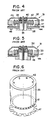
- FIG. 4 of the accompanying drawings shows a motor having such a prior art frequency generator.
- a depressed cup-shaped rotor yoke 32 of a motor 31 includes a rotary shaft 35 in an integral form, and the rotary shaft 35 is rotatably supported by a bearing 40 in a cylindrical holder portion 39 provided in a stationary drum of a rotary cylinder head.
- a motor mounting portion 38 is provided in a part of the stationary drum in the form of a step.
- On the motor mounting portion 38 are mounted a printed wiring board 44 and an iron board 46 in piles, with their center holes engaging the holder portion 39.
- the iron board 46 is further overlaid with a stator core 42 which encircles the holder portion 39.
- the stator core 42, iron board 46 and wiring board 44 are fixed on the stationary drum by applying screws passing through themselves to the motor mounting portion 38.
- a driving coil 43 of a predetermined number of phases is wound on the stator core 42.
- a cylindrical rotor magnet 33 On the inner circumferential surface of the rotor yoke 32 is secured a cylindrical rotor magnet 33 whose inner circumferential surface is opposed to the outer circumferential surface of the stator core 42, maintaining a predetermined distance therebetween.
- the rotor magnet 33 is magnetized in the thickness direction thereof throughout its substantially entire portion except its lower end portion as shown in Figure 6 to form a predetermined number of magnetic poles (6 poles in the illustrated example) in the circumferential direction to behave as a magnet portion 52.
- the lower end of the rotor magnet 33 is magnetized in the axial direction to form an adequate number of magnetic poles (for example, 24 poles) in the circumferential direction to behave as a magnetic flux generating portion 51 of the frequency generator.
- the wiring board 44 is a single-surface printed board, and appropriate circuit elements 48 are provided on the printed surface. On the opposite surface of the wiring board 44 is overlaid the iron board 46.
- Figure 5 of the accompanying drawings shows an example where the printed board 44 is a double-surface printed board. On one of the printed surfaces is provided appropriate circuit elements 48, and on the other printed surface is provided the generating coil pattern 47 of the frequency generator, thereby omitting the iron board 46 used in the example of Figure 4.
- the use of both the circuit board and the iron board increases the number of parts and increases the manufacturing cost.
- the use of the double-surface printed board in the prior art of Figure 5 also increases the manufacturing cost.
- the circuit board is manufactured by first etching a large board material to form a number of generating coil patterns thereon and by subsequently press-cutting the large board material into respective circuit boards and concurrently punching out center holes for engagement with the holder portion. Therefore, a positional inconsistency often occurs between the center of the center hole and the center of the generating coil pattern.
- the center of the generating coil pattern deviates from the rotation center when the center hole of the circuit board engages the holder portion. This increases the wow flutter of the output of the frequency generator.
- a frequency generator including a rotary body which is arranged to rotate about a shaft, a magnetic flux generating portion which is arranged to rotate co-axially of the shaft, a generating coil pattern opposed to the magnetic flux generating portion and a circuit board, wherein the circuit board has one surface on which the generating coil pattern and a wiring pattern for connection among circuit elements and an external circuit are disposed, and the generating coil pattern is printed on an insulating layer which is provided on the wiring pattern.
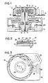
- a frequency generator is described below in detail, referring to Figures 1 to 3 and, for example, may be used in a driving motor for driving a rotary cylinder head.
- a driving motor 1 for rotating a rotary cylinder head has a depressed cup-shaped rotor yoke 2.
- a rotary shaft 5 In the center of the rotor yoke 2 is mounted an end of a rotary shaft 5 via a boss 4.
- a stationary drum 7 of the rotary cylinder head has a cylindrical holder portion 9 in the form of a projection at one end thereof.
- the rotary shaft 5 is rotatably supported by a pair of upper and lower bearings 10-10 in the holder portion 9.
- the stationary drum 7 has a step-shaped motor mounting portion 8 between the major body and the holder portion 9 thereof.
- a printed wiring board 14 is disposed on the motor mounting portion 8, with its center hole engaging the holder portion 9.
- stator core 12 of the motor 1 which encircles the holder portion 9.
- the stator core 12 and the wiring board 14 are fixed to the stationary drum 7 by fixing screws which pass through these members and engage the motor mounting portion 8.
- driving coil 13 On the stator core 12 is wound a driving coil 13 of a predetermined number of phases.
- a cylindrical rotor magnet 3 On the inner circumferential surface of the rotor yoke 2 is fixed a cylindrical rotor magnet 3, maintaining a distance between the inner circumferential surface thereof and the outer circumferential surface of the stator core 12.
- the rotor magnet 3 has the same structure as shown in Figure 6. That is, most part thereof except the lower end is magnetized in the thickness direction to form a predetermined number of magnetic poles in the circumferential direction to behave as a driving magnet portion.
- the lower end of the rotor magnet 3 is magnetized in the axial direction to form a predetermined number of magnetic poles to behave as a magnetic flux generating portion of the frequency generator.
- the lower end of the rotary shaft 5 extends beyond the lower surface of the stationary drum 7, and a rotary drum 19 is mounted on the extended end of the rotary shaft 5 via a disk 18.
- the rotary drum 19 and the stationary drum 7 form a rotary magnetic head generally used in a video tape recorder, digital audio tape recorder, etc. More specifically, a magnetic head 20 is mounted on the rotary drum 19, with its tape-contact surface being exposed through a gap between the rotary drum 19 and the stationary drum 7. Further, a rotary transformer 21 for sending or receiving signals to or from the magnetic head 20 is mounted on both drums 19 and 7.
- the rotary drum 19 and the rotor yoke 2 of the motor 1 form a rotary body which rotates together with the magnetic flux generating portion of the frequency generator.
- the wiring board 14 consists of a base element 22, a resist layer 23 formed on one surface of the base element 22, a wiring pattern 24 formed on the resist layer 23 by etching or other process, and a resist layer 25 covering the wiring pattern 24.
- an undercoat 26 as an insulating layer, and a generating coil pattern 27 is printed on the undercoat 26. Therefore, the generating coil pattern 27 is superposed on the wiring pattern 24 via the insulative undercoat 26.
- the generating coil pattern 27 may be formed by printing silver paste or other conductive material.
- On the generating coil pattern 27 is provided an overcoat 28.
- the wiring pattern 24 is first formed on the board material by copper etching or other process.
- the board material is subsequently cut and divided into individual circuit board members.
- Each board member is subsequently properly positioned, referring to its center hole 29 shown in Figure 3 which has been formed previously, and the generating coil 27 is printed around the center hole 29.
- the generating coil pattern 27 is in the form of annularly continuous waves, as viewed in a greater detail as shown in Figure 3.
- the annular generating coil pattern 27 is printed, with its center coinciding with the center of the center hole 29.
- An end of the wiring pattern 24 is connected to a connector 30.
- the wiring board 14 is fixed to the motor mounting portion 8 by engaging the center hole 29 with the holder portion 9 of the stationary drum 7. Therefore, by improving the roundness of the outer circumference of the holder portion 9 and the engaging accuracy between the center hole 29 and the holder portion 9, the rotary shaft 5 and the center hole 29 are held in a proper concentric relationship.
- centers of the rotary shaft 5 and the generating coil pattern 27 coincide so as to diminish the wow flutter of the output of the frequency generator comprising the magnetic flux generating portion of the rotor magnet 3 and the generating coil pattern 27 which are held in an opposed relationship.
- the rotary magnetic head In a normal operative condition, the rotary magnetic head is positioned in the upper side, and the driving motor is positioned in the lower side.
- Figure 1 shows the rotary magnetic head in the lower side and shows the motor 1 in the upper side for a better understanding of the system.
- the generating coil pattern 27 is provided on the wiring pattern 24 of the circuit board 14 via the insulating layer 26, the generating coil pattern 27 of the frequency generator can be formed, using a single-surface printed board having a small pattern forming area. Therefore, it is not necessary to pile two circuit boards or use a double-surface printed board, and it is possible to provide an economical frequency generator. Further, the generating coil pattern 27 which is never interfered by the wiring pattern 24 can be provided in a continuous form throughout the entire circumference without being cut off at any point thereof.
- the generating coil pattern 27 is printed, referring to the center hole 29 of the circuit board 14 which is held concentic of the rotary shaft 5 of the motor 1 as a rotary body, positional deviation of the center of the generating coil pattern 27 is substantially removed, and the wow flutter in the output of the frequency generator is diminished to a very small value.
- the magnetic flux generating portion of the frequency generator may be a separate member independent of the rotor magnet of the motor so as to be fixed to an end surface of the rotor magnet or mounted in a position other than the rotor magnet.
- the frequency generator may be used not only in a driving motor for driving a rotary cylinder head but also in detection of the speed of a rotary multi-surface mirror device or other rotary body.
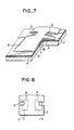
- a printed wiring board formed by providing a lower conductive pattern (wiring pattern) C on an insulating base plate D and by overlaying an upper conductive pattern (generating coil pattern) A on the lower conductive pattern D via an insulating layer (undercoat) B. Electrodes of the upper and lower conductive patterns A and C are connected together, and an overcoat E is provided on the upper conductive pattern A except at least a selected portion of the electrode.
- F designates a resist layer other than the insulating layer B. Further, the insulating layer B is partly removed to provide an opening I at a portion corresponding to an electrode H where the lower conductive pattern and the upper conductive pattern are connected.
- a portion g in the form of a cutout, for example, not covered by the overcoat E is provided at a portion above a contacting portion of the upper and lower conductive patterns A and C. Therefore, when gas is generated from the upper conductive pattern A due to heat which is applied after the overcoating, the gas is discharged to the exterior through the exposed portion g to remove dry spots in the contact portion.
- the conductor surface is exposed in a small limited area alone to substantially prevent migration (a phenomenum that ions are moved by an electric field.
- ions evaporate from a metal conductor surface in presence of chlorine or other impurity element and humidity and move to another conductor having a different potential thereby to produce incomplete insulation on a substrate surface).
- a metal plating layer a is provided on an electrode H of a copper etching pattern C formed on an insulating base plate D. Therefore, the metal plating layer a reduces the influence of heat applied in the process of providing an insulating layer B or the influence of the environment, so as to prevent oxidation of the electrode H of the copper etching pattern C. Therefore, a better contact between the electrode H of the copper etching pattern C and the electrode of the generating coil pattern A is maintained to prevent non-conduction at the connected portion.
- solder or nickel forming the metal plating layer a are less subject to oxidation than copper and conjoin well with the electrode of the generating coil pattern, they are suitable for use as a plating material.
- F designates a resist layer
- E denotes an overcoat layer provided on the generating coil pattern A to protect same.
- the generating coil pattern of the frequency generator is provided on the wiring pattern of the circuit board via the insulating layer, it is possible to form the generating coil pattern, using a printing board having a single printing surface and a small pattern forming area. Therefore, it is not necessary to use two circuit boards in pile or use a wiring board having double printing surfaces. As a result, an economical frequency generator can be provided. Further, since the generating coil pattern can be printed, referring to the center hole of the circuit board which is concentric with the rotary body, positional deviation of the center of the generating coil is substantially removed, and the wow flutter of the output of the frequency generator is significantly diminished.
Landscapes
- Physics & Mathematics (AREA)
- General Physics & Mathematics (AREA)
- Engineering & Computer Science (AREA)
- Power Engineering (AREA)
- Optics & Photonics (AREA)
- Permanent Magnet Type Synchronous Machine (AREA)
- Brushless Motors (AREA)
- Windings For Motors And Generators (AREA)
Applications Claiming Priority (6)
| Application Number | Priority Date | Filing Date | Title |
|---|---|---|---|
| JP9181288U JPH0214266U (fr) | 1988-07-11 | 1988-07-11 | |
| JP91812/88 | 1988-07-11 | ||
| JP1988168809U JPH06849Y2 (ja) | 1988-12-27 | 1988-12-27 | 印刷配線基板 |
| JP168808/88 | 1988-12-27 | ||
| JP168809/88 | 1988-12-27 | ||
| JP16880888U JPH0291478U (fr) | 1988-12-27 | 1988-12-27 |
Publications (2)
| Publication Number | Publication Date |
|---|---|
| EP0351175A2 true EP0351175A2 (fr) | 1990-01-17 |
| EP0351175A3 EP0351175A3 (fr) | 1990-06-06 |
Family
ID=27306849
Family Applications (1)
| Application Number | Title | Priority Date | Filing Date |
|---|---|---|---|
| EP89307008A Withdrawn EP0351175A3 (fr) | 1988-07-11 | 1989-07-11 | Générateur de fréquences |
Country Status (2)
| Country | Link |
|---|---|
| US (1) | US4975607A (fr) |
| EP (1) | EP0351175A3 (fr) |
Cited By (2)
| Publication number | Priority date | Publication date | Assignee | Title |
|---|---|---|---|---|
| EP0441376A3 (en) * | 1990-02-07 | 1992-12-09 | Kabushiki Kaisha Sankyo Seiki Seisakusho | Frequency generator |
| CN102403865A (zh) * | 2011-11-22 | 2012-04-04 | 奇瑞汽车股份有限公司 | 一种非接触式位置检测的汽车空调无刷直流电机 |
Families Citing this family (21)
| Publication number | Priority date | Publication date | Assignee | Title |
|---|---|---|---|---|
| US5240003A (en) * | 1989-10-16 | 1993-08-31 | Du-Med B.V. | Ultrasonic instrument with a micro motor having stator coils on a flexible circuit board |
| KR910010797A (ko) * | 1989-11-29 | 1991-06-29 | 서주인 | 주파수발전기의 코일패턴 |
| JPH0580104A (ja) * | 1991-09-20 | 1993-04-02 | Cmk Corp | モータ用プリント配線板の製造方法 |
| US20070016071A1 (en) * | 1993-02-01 | 2007-01-18 | Volcano Corporation | Ultrasound transducer assembly |
| US5453575A (en) | 1993-02-01 | 1995-09-26 | Endosonics Corporation | Apparatus and method for detecting blood flow in intravascular ultrasonic imaging |
| JPH0833300A (ja) * | 1994-07-14 | 1996-02-02 | Matsushita Electric Ind Co Ltd | ブラシレスモータ |
| DE4438132A1 (de) * | 1994-10-27 | 1996-05-02 | Wilo Gmbh | Spaltrohrpumpe |
| JP3458917B2 (ja) * | 1995-07-06 | 2003-10-20 | ミネベア株式会社 | モータ構造 |
| US5770902A (en) * | 1995-11-02 | 1998-06-23 | Globe Motors | Motor termination board |
| JPH09182399A (ja) * | 1995-12-22 | 1997-07-11 | Sony Corp | モータ及び回転磁気ヘッド装置 |
| US7226417B1 (en) | 1995-12-26 | 2007-06-05 | Volcano Corporation | High resolution intravascular ultrasound transducer assembly having a flexible substrate |
| US5717268A (en) * | 1996-06-17 | 1998-02-10 | Philips Electronics North America Corp. | Electric motor with tachometer signal generator |
| US5857974A (en) | 1997-01-08 | 1999-01-12 | Endosonics Corporation | High resolution intravascular ultrasound transducer assembly having a flexible substrate |
| FR2766607B1 (fr) * | 1997-07-23 | 1999-10-01 | Hutchinson | Actionneur electromagnetique, et support antivibratoire hydraulique comportant un tel actionneur |
| DE19851060A1 (de) * | 1998-11-05 | 2000-05-18 | Trw Automotive Electron & Comp | Elektromotorischer Antrieb, insbesondere für eine Pumpe für ein Servo-Lenksystem eines Kraftfahrzeugs |
| US20040054287A1 (en) * | 2002-08-29 | 2004-03-18 | Stephens Douglas Neil | Ultrasonic imaging devices and methods of fabrication |
| US8647281B2 (en) * | 2009-03-31 | 2014-02-11 | Boston Scientific Scimed, Inc. | Systems and methods for making and using an imaging core of an intravascular ultrasound imaging system |
| US8298149B2 (en) * | 2009-03-31 | 2012-10-30 | Boston Scientific Scimed, Inc. | Systems and methods for making and using a motor distally-positioned within a catheter of an intravascular ultrasound imaging system |
| US20100249604A1 (en) * | 2009-03-31 | 2010-09-30 | Boston Scientific Corporation | Systems and methods for making and using a motor distally-positioned within a catheter of an intravascular ultrasound imaging system |
| US20110071400A1 (en) * | 2009-09-23 | 2011-03-24 | Boston Scientific Scimed, Inc. | Systems and methods for making and using intravascular ultrasound imaging systems with sealed imaging cores |
| US20110071401A1 (en) * | 2009-09-24 | 2011-03-24 | Boston Scientific Scimed, Inc. | Systems and methods for making and using a stepper motor for an intravascular ultrasound imaging system |
Family Cites Families (7)
| Publication number | Priority date | Publication date | Assignee | Title |
|---|---|---|---|---|
| DE2215673A1 (de) * | 1972-03-30 | 1973-10-04 | Bosch Gmbh Robert | Mechanisch-elektrischer wandler |
| JPS5833958A (ja) * | 1981-08-18 | 1983-02-28 | Kangiyou Denki Kiki Kk | モ−タ用シ−トコイル |
| JPS6055271U (ja) * | 1983-09-23 | 1985-04-18 | ジェコ−株式会社 | マイクロモ−タの速度発電機 |
| CA1244867A (fr) * | 1984-04-27 | 1988-11-15 | Sanyo Electric Co., Ltd. | Moteur sans balais |
| JPS62262645A (ja) * | 1986-05-09 | 1987-11-14 | Sanyo Electric Co Ltd | ブラシレスモ−タ |
| JPS63262038A (ja) * | 1987-04-16 | 1988-10-28 | Asahi Chem Ind Co Ltd | Fgコイル付きモ−タ用プリントコイル |
| CA1249064A (fr) * | 1987-07-06 | 1989-01-17 | Reginald B.P. Bennett | Methode d'application de conducteurs de recouvrement sur la surface d'une carte de circuits imprimes |
-
1989
- 1989-07-07 US US07/376,847 patent/US4975607A/en not_active Expired - Fee Related
- 1989-07-11 EP EP89307008A patent/EP0351175A3/fr not_active Withdrawn
Cited By (4)
| Publication number | Priority date | Publication date | Assignee | Title |
|---|---|---|---|---|
| EP0441376A3 (en) * | 1990-02-07 | 1992-12-09 | Kabushiki Kaisha Sankyo Seiki Seisakusho | Frequency generator |
| US5260619A (en) * | 1990-02-07 | 1993-11-09 | Kabushiki Kaisha Sankyo Seiki Seisakusho | Frequency generator |
| CN102403865A (zh) * | 2011-11-22 | 2012-04-04 | 奇瑞汽车股份有限公司 | 一种非接触式位置检测的汽车空调无刷直流电机 |
| CN102403865B (zh) * | 2011-11-22 | 2013-07-17 | 奇瑞汽车股份有限公司 | 一种非接触式位置检测的汽车空调无刷直流电机 |
Also Published As
| Publication number | Publication date |
|---|---|
| EP0351175A3 (fr) | 1990-06-06 |
| US4975607A (en) | 1990-12-04 |
Similar Documents
| Publication | Publication Date | Title |
|---|---|---|
| US4975607A (en) | Frequency generator with superimposed generation coil | |
| US4668884A (en) | Brushless motor | |
| GB1591236A (en) | Guide drum in a magnetic recording and/or reproducing apparatus | |
| US4347536A (en) | Rotary cylinder apparatus | |
| JPH01130509A (ja) | 回転トランスフォーマ | |
| US5764443A (en) | Rotary transformer with flexible printed circuit boards | |
| KR860002893A (ko) | 전자적으로 정류되는 직류기 및 그 사용방법 | |
| JPH09149602A (ja) | 回転電機 | |
| US6369991B1 (en) | Head drum apparatus | |
| JP3163607B2 (ja) | 回転磁気ヘッド装置 | |
| US7280318B2 (en) | Head drum assembly for a tape recorder | |
| JP3432361B2 (ja) | スピンドルモータ | |
| KR0151880B1 (ko) | 회전 헤드 장치 | |
| KR0138942B1 (ko) | 로터리 트랜스 | |
| KR100213069B1 (ko) | 박막자기트랜스를 갖는 테이프레코더의 헤드드럼 | |
| JPH0519841Y2 (fr) | ||
| KR200306186Y1 (ko) | 테이프레코더의헤드드럼과메인회로기판의전기적연결장치 | |
| US5793575A (en) | Rotary transformer for a video cassette recorder having a stator and a rotor equipped with coils | |
| JPS642534Y2 (fr) | ||
| JP2814508B2 (ja) | 回転ヘッド装置 | |
| JPH10112002A (ja) | 回転磁気ヘッド装置 | |
| JPH0678507A (ja) | ラジアル型アウターロータ方式ブラシレスモータ | |
| KR970002144Y1 (ko) | 회전식 헤드드럼 | |
| JPH0355102Y2 (fr) | ||
| JP4000311B2 (ja) | テープレコーダのヘッドドラム組立体 |
Legal Events
| Date | Code | Title | Description |
|---|---|---|---|
| PUAI | Public reference made under article 153(3) epc to a published international application that has entered the european phase |
Free format text: ORIGINAL CODE: 0009012 |
|
| AK | Designated contracting states |
Kind code of ref document: A2 Designated state(s): DE FR GB NL |
|
| PUAL | Search report despatched |
Free format text: ORIGINAL CODE: 0009013 |
|
| RHK1 | Main classification (correction) |
Ipc: H02K 3/36 |
|
| AK | Designated contracting states |
Kind code of ref document: A3 Designated state(s): DE FR GB NL |
|
| RHK1 | Main classification (correction) |
Ipc: H02K 3/26 |
|
| 17P | Request for examination filed |
Effective date: 19901129 |
|
| 17Q | First examination report despatched |
Effective date: 19920611 |
|
| STAA | Information on the status of an ep patent application or granted ep patent |
Free format text: STATUS: THE APPLICATION IS DEEMED TO BE WITHDRAWN |
|
| 18D | Application deemed to be withdrawn |
Effective date: 19930407 |