EP0352040B1 - Gerät zur automatischen schaltungsinternen Prüfung von Teilnehmerschaltungen und Verfahren - Google Patents
Gerät zur automatischen schaltungsinternen Prüfung von Teilnehmerschaltungen und Verfahren Download PDFInfo
- Publication number
- EP0352040B1 EP0352040B1 EP89307191A EP89307191A EP0352040B1 EP 0352040 B1 EP0352040 B1 EP 0352040B1 EP 89307191 A EP89307191 A EP 89307191A EP 89307191 A EP89307191 A EP 89307191A EP 0352040 B1 EP0352040 B1 EP 0352040B1
- Authority
- EP
- European Patent Office
- Prior art keywords
- ring
- signals
- tip
- pins
- subscriber line
- Prior art date
- Legal status (The legal status is an assumption and is not a legal conclusion. Google has not performed a legal analysis and makes no representation as to the accuracy of the status listed.)
- Expired - Lifetime
Links
- 238000012360 testing method Methods 0.000 title claims description 113
- 238000000034 method Methods 0.000 title claims description 23
- 238000002955 isolation Methods 0.000 claims description 4
- 230000006870 function Effects 0.000 description 15
- 239000000523 sample Substances 0.000 description 13
- 230000008878 coupling Effects 0.000 description 9
- 238000010168 coupling process Methods 0.000 description 9
- 238000005859 coupling reaction Methods 0.000 description 9
- 238000010586 diagram Methods 0.000 description 7
- 230000008569 process Effects 0.000 description 6
- 238000004519 manufacturing process Methods 0.000 description 5
- 238000013461 design Methods 0.000 description 4
- 238000001514 detection method Methods 0.000 description 3
- 230000000694 effects Effects 0.000 description 3
- 230000005236 sound signal Effects 0.000 description 3
- 238000012956 testing procedure Methods 0.000 description 3
- 230000000712 assembly Effects 0.000 description 2
- 238000000429 assembly Methods 0.000 description 2
- 230000002950 deficient Effects 0.000 description 2
- 238000005259 measurement Methods 0.000 description 2
- 238000012545 processing Methods 0.000 description 2
- 238000003908 quality control method Methods 0.000 description 2
- 238000011144 upstream manufacturing Methods 0.000 description 2
- 230000003213 activating effect Effects 0.000 description 1
- 238000013459 approach Methods 0.000 description 1
- 230000008901 benefit Effects 0.000 description 1
- 230000005540 biological transmission Effects 0.000 description 1
- 238000006243 chemical reaction Methods 0.000 description 1
- 230000001934 delay Effects 0.000 description 1
- 230000003831 deregulation Effects 0.000 description 1
- 230000006872 improvement Effects 0.000 description 1
- 230000035755 proliferation Effects 0.000 description 1
- 238000000926 separation method Methods 0.000 description 1
- 230000011664 signaling Effects 0.000 description 1
- 230000009131 signaling function Effects 0.000 description 1
- 230000000638 stimulation Effects 0.000 description 1
- 238000010998 test method Methods 0.000 description 1
Images





Classifications
-
- H—ELECTRICITY
- H04—ELECTRIC COMMUNICATION TECHNIQUE
- H04M—TELEPHONIC COMMUNICATION
- H04M3/00—Automatic or semi-automatic exchanges
- H04M3/005—Interface circuits for subscriber lines
-
- H—ELECTRICITY
- H04—ELECTRIC COMMUNICATION TECHNIQUE
- H04M—TELEPHONIC COMMUNICATION
- H04M3/00—Automatic or semi-automatic exchanges
- H04M3/22—Arrangements for supervision, monitoring or testing
- H04M3/26—Arrangements for supervision, monitoring or testing with means for applying test signals or for measuring
- H04M3/28—Automatic routine testing ; Fault testing; Installation testing; Test methods, test equipment or test arrangements therefor
- H04M3/30—Automatic routine testing ; Fault testing; Installation testing; Test methods, test equipment or test arrangements therefor for subscriber's lines, for the local loop
-
- H—ELECTRICITY
- H04—ELECTRIC COMMUNICATION TECHNIQUE
- H04M—TELEPHONIC COMMUNICATION
- H04M3/00—Automatic or semi-automatic exchanges
- H04M3/02—Calling substations, e.g. by ringing
Definitions
- This invention relates to the in-circuit functionality testing of hybrid circuit components, i.e., circuits having both analog and digital components and input/output ports; and, in particular, to an apparatus and method for the automatic in-circuit testing of subscriber line interface circuits.
- a subscriber line interface circuit finds application in the telecommunications industry for interfacing analog instruments such as telephones, FSK Modems, fax machines and the like to telephone digital switching and transmission network equipment.
- SLIC perform multiple functions.
- the SLIC is responsible for the direct interface between the telephone line and the low level signal processing components on a telecommunications line card. Both voice (audio in a range of 300 Hz to 3 KHz) and signalling information are processed by the SLIC.
- the SLIC performs the conventional BORSCHT functions-i.e., Battery feed (power to the telephone), Over-voltage protection, Ringing, Supervision (on or off hook status), Coding, Hybrid (2 to 4 wire conversion), and Test, see e.g. DE-A-3 215 680.
- a SLIC circuit generally comprises a component of an overall telecommunications card. While the card may be functionally tested at the inputs and outputs of the card, an "in-circuit test" may be desirable as a means by which to identify specific SLIC problems independently of other circuitry on the card. The in-circuit test is thus a manufacturing diagnostic tool aimed at reducing the overall manufacturing cost of the card.
- in-circuit tests or measurements refer to printed circuit board test procedures which, through the use of various isolation techniques, perform "pin checks” and "gross functionality tests” on an individual circuit regardless of the specific circuit configuration or the effects of the surrounding components.
- Pin checks are tests specifically designed to verify appropriate electrical activity on all device pins (i.e., the physical connections on the card to the specific SLIC circuit).
- Gross functionality tests are more comprehensive than pin checks and refer to tests designed to verify the basic function of the SLIC in addition to simply verifying pin activity. It is to be expressly understood that neither the pin check test or the gross functionality test provides for a full functionality test of the SLIC circuit specification.
- the above described problem is solved and a technical advance achieved in the field by the programmatically generated in-circuit test apparatus and method of the present invention for subscriber line interface circuits.
- the present invention is an automated apparatus and method for in-circuit testing of the subscriber line interface circuit mounted on a telecommunication card.
- the subscriber line interface circuit is interconnected with other associated components on the card.
- the subscriber line interface circuit conventionally has tip and ring pins, transmit and receive pins, and ring control, hook status, and ring trip pins.
- the automated apparatus of the present invention connects to the tip, ring, and transmit pins, during a first test, for applying at least one analog AC voltage signal across the tip and ring pins and then recording the resulting transmit signal present on the transmit pin.
- the apparatus then connects to the tip, ring, and receive pins for applying, during a second test, at least one analog AC voltage signal to the receive pin and then recording the resulting receive signals on the tip and ring pins.
- the apparatus of the present invention In order to apply the at least one analog AC voltage signal, the apparatus of the present invention must electrically overdrive any analog signal present on the receive pin when the telecommunication card is powered up.
- the apparatus of the present invention then connects to the hook status, tip and ring pin for applying, during a third test, offhook and onhook signals to the tip and ring pins and receiving the resulting hook status signals on the hook status pin.
- the apparatus of the present invention connects to the ring control, ring trip and the tip and ring pins for applying, during a fourth test, a ring command to the ring control pin.
- the apparatus of the present invention then records resulting ringing signal across the tip and ring pins and then applies an offhook signal to the tip and ring pins and receives the resulting ring trip signal on the ring trip pin.
- the apparatus of the present invention for each of these tests receives the transmit, receive, hook status, ringing and ring trip signals and compares each signal to an expected signal. In the event that any received signal falls outside a predetermined range of the expected signal, a fail signal, for the SLIC, under test, is issued. Otherwise the SLIC passes and the apparatus of the present invention releases all relays and becomes ready for the next testing procedure.
- a typical telecommunications card 100 is shown in Figure 1 which carries a SLIC 110 and other telephony components such as a CODEC 115.
- a CODEC is an acronym for COder-DECoder and refers to a class of integrated circuits used in the telecommunications industry. It is to be expressly understood that a conventional telecommunications card 100 may have a variety of other hybrid components located on the printed circuit board.
- the SLIC 110 conventionally receives a tip 120 and ring 130 signal from a line or pin connection which is interconnected to the card such as inputs 120a and 130a to the card 100.
- the tip 120 and ring 130 are conventionally interconnected to a telecommunication device such as a telephone instrument, not shown.
- the SLIC 110 delivers an analog transmit signal to the CODEC 120 over line or pin 140.
- the CODEC 120 delivers an analog receive signal over line 150 to the SLIC 110.
- the CODEC is interconnected over lines 115a to other components on the telecommunications card 100 through, typically, a PCM backplane.
- the SLIC 110 also receives a ring control signal over line 160 from an associated component 160a also located on card 100.
- the SLIC in turn, delivers a hook status signal on line 170 to an associated component 170a and a ring trip signal on line 180 to an associated component 180a.
- the SLIC receives power and ground over lines 190.
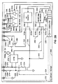
- FIGs 2a and 2b the configuration for the in-circuit testing of the SLIC 110, under the teachings of the present invention, is set forth.
- the telecommunications card 100 is placed on a fixture, not shown, wherein the in-circuit tester 200 of the present invention accesses the SLIC 110 input and output by means of mechanical test probes 210 that engages the actual pins.
- the in-circuit tester 200 utilizes a computer 220 as an overall control of the present invention.
- the computer 220 can be actually located in the tester or it can be remote therefrom.
- Computer 220 over lines 222 control scanning relays 230 in a fashion to be described subsequently and over line 224 also operates relay 232.
- the computer also operates a relay multiplexer 223 over lines 221.
- the computer 220 also operates a waveform recorder 240 over lines 226, an AC source 250 over lines 228, and a bank of digital drivers and receivers 260 over lines 262.
- the computer 220 has an internal memory 220a for storing the program of the present invention as well as a memory portion 220b for storing "expected" signals from the SLIC 110 under test and a memory portion 220c for storing the "actual” signals resulting from the testing of the SLIC.
- the waveform recorder 240 is selectively interconnected by a relay 223a over line 242 to a coupling transformer 234, by a relay 223b over line 244 to an attenuator 270 and by a relay 223c over line 246 to the transmit input to the SLIC on line 140.
- the AC source 250 is also connected to the coupling transformer 234 by a relay 223d over line 242 and is further interconnected by a relay 223e over line 252 to an analog overdrive amplifier 280.
- the overdrive amplifier 280 produces a minimum output current of 150 mA with a maximum output impedance of 3.0 ohms.
- the AC source 250 is an alternating current/voltage source having a range of +/- 10 volts at a minimum resolution of 3.0 mV with an accuracy of +/- 0.1% and a frequency range of 0.5 Hz to 20 KHz with a resolution of 0.5 Hz and an accuracy of +/- 0.5%.
- the output of the overdrive amplifier 280 is delivered over line 282 through relay 230e.
- the remaining input to the amplifier is delivered from relay 230d over line 284.
- the attenuator 270 is interconnected over line 272 to scanning relay 230c and over line 274 to scanning relay 230b.
- relay 232 is connected to lines 272 and 274 as shown in Figure 2b.
- the digital driver 260c and receivers 260a and 260b are selectively interconnected over lines 266, 262, and 264, respectively.
- the overdriving digital driver 260c operates in a range of -3.5 to +5.0 DC volts at a minimum resolution of 5.0 mV and a current capability of +/- 500 MA.
- the in-circuit tester 200 communicates with the SLIC 110, under test, through the scanner relays 230 which are connected to mechanical probes 210 on a test fixture, not shown.
- the mechanical and electrical connections are shown in Figure 2 with the probes engaging the selected pins of the SLIC 110, under test, and ready for the pin checks and gross functionality tests of the present invention as set forth in the following.
- the probes 210 physically make contact with the printed circuit pins, pads or points for the input and output lines of the SLIC 110. In this position, power can be selectively provided to the card.
- Tip and Ring date back to old patch panel telephone switchboards and refer to the physical tip and ring connection on patch board plugs.
- the tip 120 and ring 130 functions to form a floating bi-directional port for an interface to a telephone instrument, not shown. Since signals on the tip 120 and ring 130 float, the connection to the in-circuit tester 200 must be made through a transformer coupler.
- Tip 120 and ring 130 serve as both an input and an output port to the SLIC 110 and the SLIC 110 functions to convert the tip and ring bi-directional port into two uni-directional lines: transmit over line 140 and receive over line 150.
- the tip and ring lines are also involved in the voice channel path and in the multiple signaling function such as hook status on pin 170 and ring tip on pin 180 and ring detection.
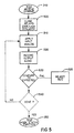
- the computer 220 is programmed in memory 220a to start 300 with a card containing a SLIC 110 on the fixture with the probes in place as shown in Figures 2a and 2b.
- the system is initially reset. and the first test to be performed is the test of the transmit channel 310 and, if it fails, then the SLIC is rejected 320 and the next card 330 is accessed. Upon failure, the next telecommunications card 100 is selected and mounted onto the test fixture. If, on the other hand, the test of the transmit channel 310 passes, the testing of the receive channel 340 commences. The system then successively tests at different time intervals the status of the hook function 350 and the ringer function 360.
- the system accepts the SLIC 370, all probes 210 are then removed and the card 100 is released from the fixture. The next card 330 is then mounted and the testing continues.
- the order of conducting these tests could be any suitable order based upon the needs of a particular customer.
- the testing procedure could stop without completing the remaining tests and the SLIC 110 under test, be rejected.
- the reject SLIC stage 320 all four tests could be completed and those tests which fail could be separately recorded for use by the operator of the system.
- the system could be programmed to conduct other in-circuit tests on other components on the same card before proceeding to the next card.
- the advantage of the in-circuit tester 200 of the present invention is that it automatically and rapidly proceeds from test to test, checks the pins and verifies gross functionality as will be discussed in the following.
- the present invention proceeds automatically and provides several orders of magnitude of speed improvement over conventional SLIC testing approaches.
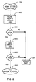
- the computer opens all relays.
- the card can now be removed and the next SLIC inserted for testing or the system can proceed with tests of other components on the same card as set forth in the above related applications.
- the present invention provides a unique means and method of programmatically generating in-circuit pin checks and gross functionality tests of subscriber line interface circuits such as those found on a telecommunications card.
- the present invention therefore, provides a method of quality control in the manufacture of printed circuit boards containing these hybrid devices.
Landscapes
- Engineering & Computer Science (AREA)
- Signal Processing (AREA)
- Monitoring And Testing Of Exchanges (AREA)
- Interface Circuits In Exchanges (AREA)
Claims (11)
- Automatisiertes Gerät (200) zur schaltungsinternen Prüfung einer Teilnehmerschaltung (110), die auf einer Telekommunikationskarte (100) aufgebaut ist, wobei die Teilnehmerschaltung mit weiteren zugeordneten Komponenten (115) auf der Karte verschaltet ist, wobei die Teilnehmerschaltung in der Lage ist, Übertragungs- (140), Telekommunikations- (120, 130), Einhängestatus- (170), Klingel- (160) und Klingelausschalte- (180) Signale zu erzeugen, wobei das automattsierte Gerät dadurch gekennzeichnet ist, daß es aufweist:
Mittel (234, 260, 280), die mit der Telekommunikationskarte zum elektrischen Isolieren der Teilnehmerschaltung von den anderen zugeordneten Komponenten auf der Karte verbunden sind;
Mittel (270, 250, 221, 232, 220), die mit den elektrischen Isoliermitteln verbunden sind, um wahlweise zu bewirken, daß die Teilnehmerschaltung die Übertragungs-, Telekommunikations-, Einhängestatus-, Klingel- und Klingelausschaltesignale durch Aufgeben von Testsignalen auf die Teilnehmerschaltung erzeugt, die irgendein analoges oder digitales Signal übersteuern, das auf der Telekommunikationskarte vorliegt,
Mittel (240, 220) in den Mitteln zum selektiven Bewirken zum Vergleichen jedes der wahlweise erzeugten Übertragungs-, Telekommunikations-, Einhängestatus-, Klingel- und Klingelausschaltesignale mit erwarteten Werten und
Mittel (220) in den Mitteln zum wahlweisen Bewirken zum Ausgeben eines Ausfallsignals, wenn irgendeines der wahlweise erzeugten Signale nicht dem erwarteten Wert entspricht. - Automatisiertes Gerät (200) zur schaltungsinternen Prüfung einer Teilnehmerschaltung (110), die auf einer Telekommunikationskarte (100) aufgebaut ist, wobei die Teilnehmerschaltung mit anderen zugeordneten Komponenten (115) auf der Karte verschaltet ist, wobei die Teilnehmerschaltung Kipp- und Klingelstifte (120, 130), Übertragungs- und Empfangsstifte (140, 150) und Klingelsteuer(160), Einhängestatus- (170) und Klingelausschalte- (180) Stifte hat, wobei das automatisierte Gerät dadurch gekennzeichnet ist, daß es aufweist:
erste Mittel (230d, 230c, 230f, 232, 234, 223d, 250, 223c, 240), die automatisch an die Kipp-, Klingel- und Übertragungsstifte geschaltet sind, um während eines ersten Zeitintervalles wenigstens ein analoges Wechselspannungssignal über die Kipp- und Klingelstifte aufzugeben, wobei die ersten Aufgabemittel weiterhin Übertragungssignale auf dem Übertragungsstift aufzeichnen,
zweite Mittel (230b, 230c, 230d, 230e, 223a, 223e, 232, 280, 250, 234, 240), die automatisch an die Kipp-, Klingel- und Empfangsstifte geschaltet sind, um während eines zweiten Zeitintervalles wenigstens ein analoges Wechselspannungssignal auf den Empfangsstift aufzugeben, wobei die zweiten Aufgabemittel weiterhin Telekommunikationssignale auf den Kipp- und Klingelstiften aufzeichnen,
dritte Mittel (230b, 230c, 230h, 232, 234, 235, 260b), die automatisch an die Einhängestatus-, Kipp- und Klingelstifte geschaltet sind, um während eines dritten Zeitintervalles Abhebe- und Auflegesignale auf die Kipp- und Klingelstifte aufzugeben, wobei die dritten Aufgabemittel Einhängestatussignale auf dem Einhängestatusstift empfangen,
vierte Mittel (230b, 230c, 230e, 223b, 270, 223b, 240, 260c), die automatisch an die Klingelsteuer-, Klingelausschalte- und Kipp- und Klingelstifte geschaltet sind, um während eines vierten Zeitintervalls einen Klingelbefehl auf den Klingelsteuerstift aufzugeben, wobei die vierten Aufgabemittel das Klingelsignal über den Kipp- und Klingelstiften aufzeichnen, wobei die vierten Aufgabemittel dann ein Abhebesignal auf die Kipp- und Klingelstifte aufgeben und das Klingelausschaltesignal auf dem Klingelausschaltestift empfangen und
Mittel (220), die das Übertragungs-, Telekommunikations-, Einhängestatus-, Klingel- und Klingelausschaltesignal empfangen, zum Vergleichen jedes der empfangenen Signale mit erwarteten Signalen, wobei die Vergleichseinrichtung Ausfallsignale ausgibt, wenn irgendeines der empfangenen Signale außerhalb eines vorbestimmten Bereiches der erwarteten Signale fällt. - Automatisiertes Gerät nach Anspruch 2, bei dem das zweite Mittel die analoge Wechselspannung auf den Empfangsstift durch elektrisches Übersteuern jedes Analogsignales auf dem Empfangsstift aufgibt und wobei das vierte Mittel den Klingelbefehl auf den Klingelsteuerstift aufgibt, indem elektrisch jedes digitale Signal auf dem Klingelsteuerstift übersteuert wird.
- Automatisiertes Gerät nach Anspruch 3, das weiterhin Mittel (280) in den zweiten Aufgabemitteln aufweist, die wenigstens ein analoges Wechselspannungssignal empfangen, um das analoge Wechselspannungssignal zu verstärken, um jedes analoge Wechselspannungssignal elektrisch zu übersteuern.
- Automatisiertes Gerät nach Anspruch 4, bei dem die Verstärkungsmittel (280) einen minimalen Ausgabestrom von 150 mA mit einer maximalen Ausgabeimpedanz von 3,0 Ohm erzeugen.
- Automatisiertes Gerät nach einem der Ansprüche 3 bis 5, das weiterhin Mittel (260c) in den vierten Aufgabemitteln aufweist, die von dem Klingelsteuerstift aufnehmen.
- Automatisiertes Gerät nach Anspruch 6, bei dem das digitale Übersteuermittel (260c) in einem Bereich von -3,5 bis 5,0 Volt bei einer minimalen Auflösung von 5,0 mV und einem Stromleistungsvermögen von +/- 500 mA arbeitet.
- Automatisiertes Gerät nach einem der Ansprüche 2 bis 7, das weiterhin Mittel (250) in den ersten und zweiten Aufgabemitteln zum Erzeugen des analogen Wechselspannungssignales aufweist, wobei die Erzeugungsmittel in der Lage sind, eine Wechselspannung in dem Bereich von +/- 10,0 Volt mit einer minimalen Auflösung von 3,0 mV mit einer Genauigkeit von +/- 0,1 % und in einem Frequenzbereich von 0,5 Hz bis kHz mit einer Auflösung von 0,5 Hz und einer Genauigkeit von +/- 0,5 % zu erzeugen.
- Verfahren zum schaltungsinternen Prüfen einer Teilnehmerschaltung (110), die auf einer Telekommunikationskarte (100) aufgebaut ist, wobei die Teilnehmerschaltung mit weiteren zugeordneten Komponenten (115) auf der Karte verschaltet ist, wobei die Teilnehmerschaltung in der Lage ist, Übertragungs- (140), Telekommunikations- (120, 130), Einhängestatus- (170), Klingel- (160) und Klingelausschalte-(180) Signale zu erzeugen, wobei das Verfahren dadurch gekennzeichnet ist, daß es die Schritte aufweist:
elektrisches Isolieren (234, 260, 280) der angeregten Teilnehmerschaltung von den anderen zugeordneten Komponenten auf der Karte,
wahlweises Veranlassen (310, 340, 350, 360) der Teilnehmerschaltung, die Übertragungs-, Telekommunikations-, Einhängestatus-, Klingel- und Klingelausschaltesignale zu erzeugen, indem Prüfsignale auf die Teilnehmerschaltung aufgegeben werden, die irgendwelche analogen oder digitalen Signale übersteuern, die auf der Telekommunikationskarte vorliegen,
Vergleichen (220) jedes selektiv erzeugten Übertragungs-, Telekommunikations-, Einhängestatus-, Klingel- und Klingelausschaltesignales mit erwarteten Werten, und
Ausgeben eines Ausfallsignals (320), wenn irgendeines der wahlweise erzeugten Signale dem erwarteten Wert nicht entspricht. - Verfahren zum schaltungsinternen Prüfen einer Teilnehmerschaltung (110), die auf einer Telekommunikationskarte (100) aufgebaut ist, wobei die Teilnehmerschaltung mit weiteren zugeordneten Komponenten (115) auf der Karte verschaltet ist, wobei die Teilnehmerschaltung Kipp- und Klingelstifte (120, 130), Übertragungs- und Empfangsstifte (140, 150) und Klingelsteuer- (160), Einhängestatus- (170) und Klingelausschalte- (180) Stifte hat, wobei das Verfahren dadurch gekennzeichnet ist, daß es die Schritte aufweist:
während eines ersten Zeitintervalles (310):(a) Aufgeben wenigstens eines analogen Wechselspannungssignals über die Kipp- und Klingelstifte, und(b) Aufzeichnen der sich ergebenden Übertragungssignale auf dem Übertragungsstift;während eines zweiten Zeitintervalles (340):(a) Aufgeben wenigstens eines analogen Wechselspannungsignals auf den Empfangsstift, und(b) Aufzeichnen der sich ergebenden Telekommunikationssignale auf den Kipp- und Klingelstiften;während eines dritten Zeitintervalles (350):(a) Aufgeben von Abhebe- und Auflegesignalen auf die Kipp- und Klingelstifte, und(b) Empfangen der sich ergebenden Einhängestatussignale auf dem Einhängestatusstift,während eines vierten Zeitintervalles:(a) Aufgeben eines Klingelbefehls auf den Klingelsteuerstift,(b) Aufzeichnen des sich ergebenden Klingelsignals über die Kipp- und Klingelstifte,(c) Aufgeben eines Auflegesignals auf die Kipp- und Klingelstifte und(d) Empfangen des sich ergebenden Klingelausschaltesignals auf dem Klingelausschaltestift,Vergleichen (220) jedes der Übertragungs-, Telekommunikations- Einhängestatus-, Klingel-, und Klingelausschaltesignale mit erwarteten Signalen und Ausgeben von Ausfallsignalen (320), wenn irgendeines der empfangenen Signale außerhalb eines vorbestimmten Bereiches der erwarteten Signale fällt. - Verfahren nach Anspruch 10, bei dem während des zweiten Zeitintervalles der Schritt (a) das Aufgeben wenigstens eines analogen Wechselspannungssignals zum elektrischen Übersteuern irgendeines Analogsignales auf dem Empfangsstift aufweist und während des vierten Zeitintervalls der Schritt (a) das Aufgeben eines Klingelbefehls zum elektrischen Übersteuern irgendeines digitalen Signals auf dem Klingelsteuerstift aufweist.
Applications Claiming Priority (2)
| Application Number | Priority Date | Filing Date | Title |
|---|---|---|---|
| US221062 | 1988-07-19 | ||
| US07/221,062 US4860332A (en) | 1988-07-19 | 1988-07-19 | Apparatus for the automatic in-circuit testing of subscriber line interface circuits and method therefor |
Publications (3)
| Publication Number | Publication Date |
|---|---|
| EP0352040A2 EP0352040A2 (de) | 1990-01-24 |
| EP0352040A3 EP0352040A3 (de) | 1991-04-17 |
| EP0352040B1 true EP0352040B1 (de) | 1994-04-20 |
Family
ID=22826174
Family Applications (1)
| Application Number | Title | Priority Date | Filing Date |
|---|---|---|---|
| EP89307191A Expired - Lifetime EP0352040B1 (de) | 1988-07-19 | 1989-07-14 | Gerät zur automatischen schaltungsinternen Prüfung von Teilnehmerschaltungen und Verfahren |
Country Status (4)
| Country | Link |
|---|---|
| US (1) | US4860332A (de) |
| EP (1) | EP0352040B1 (de) |
| JP (1) | JP3041624B2 (de) |
| DE (1) | DE68914738T2 (de) |
Families Citing this family (19)
| Publication number | Priority date | Publication date | Assignee | Title |
|---|---|---|---|---|
| US5319631A (en) * | 1988-09-22 | 1994-06-07 | Siemens Aktiengesellschaft | Method for measuring in the subscriber area of an integrated services digital network system |
| CA1311570C (en) * | 1989-06-28 | 1992-12-15 | Thomas Gray | Apparatus for testing spare line circuits in a communication system |
| JPH05130667A (ja) * | 1991-11-07 | 1993-05-25 | Fujitsu Ltd | 遠隔加入者制御システム |
| NL9301094A (nl) * | 1993-06-23 | 1995-01-16 | Nederland Ptt | Inrichting voor het meten van analoge telefoniesignalen. |
| US5436953A (en) * | 1993-07-02 | 1995-07-25 | Northern Telecom Limited | Digital longitudinal balance measurement |
| US5521959A (en) * | 1994-02-09 | 1996-05-28 | Harris Corporation | Programmable source for supplying controllably variable AC/DC voltage output for telephone line measurement apparatus |
| US5717736A (en) * | 1995-11-03 | 1998-02-10 | Harris Corporation | Testing circuit and method for a codec hybrid balance network |
| US5881129A (en) * | 1996-05-10 | 1999-03-09 | Chen; Robert Kuo-Wei | Self-monitoring line interface circuit |
| US5982815A (en) * | 1996-07-01 | 1999-11-09 | Advanced Micro Devices Inc. | Circuit for setting a device into a test mode by changing a first port to a fixed clock and a second port to a non-fixed clock |
| US5872842A (en) * | 1996-12-27 | 1999-02-16 | Scientific-Atlanta, Inc. | Unbalanced ringing using a balanced ringing generator of a subscriber line interface circuit |
| US5960060A (en) * | 1997-08-19 | 1999-09-28 | J. V. Technologies, Inc. | Line tester for coin-operated telephones |
| US6519322B1 (en) | 1998-12-10 | 2003-02-11 | Intersil Corporation | Apparatus and method for testing subscriber loop interface circuits |
| WO2002021811A2 (en) * | 2000-09-06 | 2002-03-14 | Polycom, Inc. | System and method for diagnosing a pots port |
| FR2870068B1 (fr) | 2004-05-04 | 2006-09-08 | Alcatel Sa | Procede de test pour equipement de ligne muni d'un circuit hybride et equipement de ligne pour mise en oeuvre |
| FR2870069A1 (fr) * | 2004-05-04 | 2005-11-11 | Alcatel Sa | Procede de test pour equipement de ligne muni d'un codec et equipement de ligne poour mise en oeuvre |
| US7129831B2 (en) * | 2004-10-22 | 2006-10-31 | Honeywell International, Inc. | System diagnostic mode for a security central station receiver |
| CN104681093B (zh) * | 2014-12-26 | 2017-10-27 | 复旦大学 | 一种半导体存储器件电学参数测试系统 |
| CN104469023A (zh) * | 2015-01-05 | 2015-03-25 | 北京飞音时代技术有限公司 | 带有用户线接口电路的设备的检测方法 |
| US9860392B2 (en) | 2015-06-05 | 2018-01-02 | Silicon Laboratories Inc. | Direct-current to alternating-current power conversion |
Family Cites Families (3)
| Publication number | Priority date | Publication date | Assignee | Title |
|---|---|---|---|---|
| DE3215680A1 (de) * | 1982-04-27 | 1983-10-27 | Siemens AG, 1000 Berlin und 8000 München | Verfahren zur pruefung einer teilnehmeranschlussschaltung sowie der daran angeschlossenen analogteilnehmerstation und teilnehmeranschlussleitung und schaltungsanordnung zur durchfuehrung des verfahrens |
| US4577072A (en) * | 1983-12-30 | 1986-03-18 | Dynascan Corporation | Telephone equipment tester |
| DE3500848C2 (de) * | 1985-01-12 | 1994-04-07 | Ant Nachrichtentech | Verfahren und Schaltungsanordnung zum Prüfen der Funktionen von Fernsprechteilnehmer-Anschlußschaltungen |
-
1988
- 1988-07-19 US US07/221,062 patent/US4860332A/en not_active Expired - Fee Related
-
1989
- 1989-07-14 EP EP89307191A patent/EP0352040B1/de not_active Expired - Lifetime
- 1989-07-14 DE DE68914738T patent/DE68914738T2/de not_active Expired - Fee Related
- 1989-07-18 JP JP1187206A patent/JP3041624B2/ja not_active Expired - Lifetime
Also Published As
| Publication number | Publication date |
|---|---|
| EP0352040A3 (de) | 1991-04-17 |
| US4860332A (en) | 1989-08-22 |
| EP0352040A2 (de) | 1990-01-24 |
| JPH0279655A (ja) | 1990-03-20 |
| JP3041624B2 (ja) | 2000-05-15 |
| DE68914738D1 (de) | 1994-05-26 |
| DE68914738T2 (de) | 1994-11-24 |
Similar Documents
| Publication | Publication Date | Title |
|---|---|---|
| US4860332A (en) | Apparatus for the automatic in-circuit testing of subscriber line interface circuits and method therefor | |
| US5018184A (en) | Automated channel test unit | |
| US5073919A (en) | Automatically testing telephone lines | |
| EP1197062B1 (de) | Signaturvorrichtung für geräteeinheiten eines in-haus-fernsprechleitungsnetzwerkes | |
| US5005197A (en) | Method and apparatus as for testing a telephone line interface card | |
| US7149285B2 (en) | Dynamic, automated double-ended system and method for testing and qualifying metallic telecommunication loops | |
| US4611101A (en) | Method and apparatus for testing communication systems | |
| CA2094080C (en) | Line/drop testing from a craft terminal using test unit | |
| US4581493A (en) | Line condition reporting system | |
| US4912755A (en) | Line current test device | |
| US5357556A (en) | System and method for telephone network testing | |
| US5173896A (en) | T-carrier network simulator | |
| WO1985002740A1 (en) | An improved maintenance termination unit | |
| US5003554A (en) | Apparatus for the automatic in-circuit testing of coder/decoder telecommunications circuits and method therefor | |
| WO1984000458A1 (en) | Automated data acquisition and analysis | |
| US5274692A (en) | Method for testing the line connection before switching from a telephone switching center to be placed out of service to a new digital telephone switching center to be placed into service | |
| US4558188A (en) | Arrangement for line jumper testing | |
| US4334129A (en) | Telephone digital office cutover system | |
| US6314086B1 (en) | Interactive contextual-based assistance for portable ISDN test set | |
| CA1211190A (en) | Arrangement for single line testing | |
| US6016058A (en) | In-service wiring verification circuitry | |
| EP1825660B1 (de) | Verfahren und system für abstandsmessungen | |
| CA1211191A (en) | Arrangement for subscriber line verification and ring testing | |
| CA1227266A (en) | Arrangement for subscriber line ring testing | |
| CA1211189A (en) | Arrangement for subscriber line ring testing |
Legal Events
| Date | Code | Title | Description |
|---|---|---|---|
| PUAI | Public reference made under article 153(3) epc to a published international application that has entered the european phase |
Free format text: ORIGINAL CODE: 0009012 |
|
| AK | Designated contracting states |
Kind code of ref document: A2 Designated state(s): DE FR GB |
|
| PUAL | Search report despatched |
Free format text: ORIGINAL CODE: 0009013 |
|
| AK | Designated contracting states |
Kind code of ref document: A3 Designated state(s): DE FR GB |
|
| 17P | Request for examination filed |
Effective date: 19910629 |
|
| 17Q | First examination report despatched |
Effective date: 19930715 |
|
| GRAA | (expected) grant |
Free format text: ORIGINAL CODE: 0009210 |
|
| AK | Designated contracting states |
Kind code of ref document: B1 Designated state(s): DE FR GB |
|
| REF | Corresponds to: |
Ref document number: 68914738 Country of ref document: DE Date of ref document: 19940526 |
|
| ET | Fr: translation filed | ||
| PLBE | No opposition filed within time limit |
Free format text: ORIGINAL CODE: 0009261 |
|
| STAA | Information on the status of an ep patent application or granted ep patent |
Free format text: STATUS: NO OPPOSITION FILED WITHIN TIME LIMIT |
|
| 26N | No opposition filed | ||
| REG | Reference to a national code |
Ref country code: GB Ref legal event code: 732E |
|
| REG | Reference to a national code |
Ref country code: GB Ref legal event code: 732E |
|
| REG | Reference to a national code |
Ref country code: FR Ref legal event code: TP |
|
| REG | Reference to a national code |
Ref country code: FR Ref legal event code: TP |
|
| REG | Reference to a national code |
Ref country code: GB Ref legal event code: IF02 |
|
| PGFP | Annual fee paid to national office [announced via postgrant information from national office to epo] |
Ref country code: FR Payment date: 20020619 Year of fee payment: 14 |
|
| PGFP | Annual fee paid to national office [announced via postgrant information from national office to epo] |
Ref country code: GB Payment date: 20020710 Year of fee payment: 14 |
|
| PGFP | Annual fee paid to national office [announced via postgrant information from national office to epo] |
Ref country code: DE Payment date: 20020730 Year of fee payment: 14 |
|
| PG25 | Lapsed in a contracting state [announced via postgrant information from national office to epo] |
Ref country code: GB Free format text: LAPSE BECAUSE OF NON-PAYMENT OF DUE FEES Effective date: 20030714 |
|
| PG25 | Lapsed in a contracting state [announced via postgrant information from national office to epo] |
Ref country code: DE Free format text: LAPSE BECAUSE OF NON-PAYMENT OF DUE FEES Effective date: 20040203 |
|
| GBPC | Gb: european patent ceased through non-payment of renewal fee |
Effective date: 20030714 |
|
| PG25 | Lapsed in a contracting state [announced via postgrant information from national office to epo] |
Ref country code: FR Free format text: LAPSE BECAUSE OF NON-PAYMENT OF DUE FEES Effective date: 20040331 |
|
| REG | Reference to a national code |
Ref country code: FR Ref legal event code: ST |