EP0352236A2 - Mini machine portative pour le pliage de tubes à entraînement manuel ou motorisé et comportant un dispositif d'engagement/dégagement automatique - Google Patents
Mini machine portative pour le pliage de tubes à entraînement manuel ou motorisé et comportant un dispositif d'engagement/dégagement automatique Download PDFInfo
- Publication number
- EP0352236A2 EP0352236A2 EP89830313A EP89830313A EP0352236A2 EP 0352236 A2 EP0352236 A2 EP 0352236A2 EP 89830313 A EP89830313 A EP 89830313A EP 89830313 A EP89830313 A EP 89830313A EP 0352236 A2 EP0352236 A2 EP 0352236A2
- Authority
- EP
- European Patent Office
- Prior art keywords
- shaft
- countermatrix
- gear
- matrix
- support
- Prior art date
- Legal status (The legal status is an assumption and is not a legal conclusion. Google has not performed a legal analysis and makes no representation as to the accuracy of the status listed.)
- Granted
Links
Images


Classifications
-
- B—PERFORMING OPERATIONS; TRANSPORTING
- B21—MECHANICAL METAL-WORKING WITHOUT ESSENTIALLY REMOVING MATERIAL; PUNCHING METAL
- B21D—WORKING OR PROCESSING OF SHEET METAL OR METAL TUBES, RODS OR PROFILES WITHOUT ESSENTIALLY REMOVING MATERIAL; PUNCHING METAL
- B21D7/00—Bending rods, profiles, or tubes
- B21D7/06—Bending rods, profiles, or tubes in press brakes or between rams and anvils or abutments; Pliers with forming dies
- B21D7/063—Pliers with forming dies
Definitions
- This invention relates to a portable manually- or motor-controlled pipe-bending minimachine which, in spite of its small size as compared with similar machines, is easier and handier to operate on site for the bending of pipes ranging 4 mm to 22 mm in diameter.
- the minimachine is provided with a reverse gear and an intermediary device built in the minimachine main body which allows the engagement and automatic disengagement of the gear drive transmitting rotary motion to the matrix-carrying shaft.
- Both the motor and the manual control lever assembly allowing alternate control of consecutive angular movements of the matrix, can be easily and quickly mounted on the main body; and the countermatrix is an interchangeable device to be mounted on a special support allowing it to be appropriately positioned at the start of a bending operation.
- the Applicant has previously proposed and constructed several portable pipe-bending machines designed to improve both the working conditions and the results, making use of the advanced techniques that have been developed in the field of pipe bending and increasingly striving to satisfy the usefulness and/or necessity requirement of producing a bent pipe free from deformations, breaks, or cracks, which might even become apparent some time later, after the bent pipe has been produced and installed, also in the event the material, diameter, and thickness of the pipe are more sensitive to stretching stresses during the bending operation.
- it is particularly worthy to point out the shape of the countermatrix groove which was described and claimed in patent No. 1.147.601 granded to the Applicant and mendioned here as reference because a countermatrix of that shape is used in this invention embodiment as well, as will be better described later.
- this invention relates to, with the aim of designing a portable pipe-bending minimachine best suited to bend pipes in a little narrower range of diameters, namely 8 to 42 mm diameters, than the one the Applicant production has been devoted to so far, and which includes other features deserving particular attention, in addition to those just mentioned.
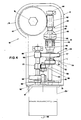
- the main body of this invention is an elongated carrying structure (11) of small size and relatively little weight as required to better meet the portability and operability requirements.
- the lower part (12) of main body (11) contains a gear drive (40) and its fore face (14) is designed and preset to mount either a motor (90) integral with it, if the gear drive (40) is to be motor-driven, or a special support (60) for manual control, as will be better explained later.
- a gear drive (40) and its fore face (14) is designed and preset to mount either a motor (90) integral with it, if the gear drive (40) is to be motor-driven, or a special support (60) for manual control, as will be better explained later.
- On said top surface is mounted a piece (28) with mounting plate (29), which is used as the horizontal axis fulcrum of a forklike lever (71) allowing manual control of gear drive (40).
- the gear drive identified by number (40) should be considered as an improvement distinguishing this machine from those previously proposed and claimed, although it includes some elements that have been described in other applications.
- the gear drive (40) substantially serves the following purposes:
- a driving section comprising gear wheels mounted on a single longitudinal shaft (95)
- a driven section comprising gear wheels mounted on a second longitudinal shaft (43), parallel with shaft (95), which mounts also a coaxial auxiliary device including an engaging/disengaging clutch (48, 46).
- the jaw (48) rotates together with shaft (43), is able to slide because it is mounted on key (51), and is urged by a compression coil spring (50) to engage with jaw (46) whereas the jaw (46) can only rotate on the longitudinal shaft together with worm gear (42) integrally formed with it, because a guide ring, or the like (47) determines its position on shaft (43).
- Shaft (43) carries a pair of coaxial, integrally mounted, reverse gear wheels (54, 55) which are locked to said shaft by means of long key (52), but can be slided along shaft (43) under the control of a lever (only represented by longitudinal line (46)), pivoting on a fixed pin (58), and whose inner arm is provided, at one end, with a roll (56) intended to favour the controlled sliding of the reverse gear assembly along the shaft and hence the meshing with the other gear wheels used for reversing purposes.
- a lever only represented by longitudinal line (46)
- a roll (56) intended to favour the controlled sliding of the reverse gear assembly along the shaft and hence the meshing with the other gear wheels used for reversing purposes.
- shaft (95) carries a gear wheel (96) meshing with gear wheel (54) of reverse gear assembly (53), and a gear wheel (97) which is constantly in mesh with intermediate gear (98) which will mesh with gear wheel (55) of the reverse gear assembly when the operator moves lever (56) to slide the reverse gear assembly along shaft (43), thus throwing gear wheel (54) out of mesh with gear wheel (96).
- the worm gear (42) meshes with helical gear wheel (41) to transmit rotary motion to the main shaft whose offset hexagon head mounts, as previously mentioned, the matrix (16) to be controlled. It is obvious that control of the matrix is obtained when jaws (48, 46) are engaged with each other as shown in Fig. 4, because the worm gear (42) will then rotate together with shaft (43) which will, in turn, be driven by either one of gear wheels (96, 97) depending on the position to which either one of mating gear wheels of reverse gear assembly (53) has been set.
- the bending member or matrix (16) schematically shown in Figs. 1 and 5 illustrating this example, is of a substantially conventional type, has a halfround groove to bend pipes up to 180°, and the centerlines of both its own groove and opposed groove (24′) of countermatrix (24) are preferably lying constantly on the same plane although both grooves will necessarily change in size depending on the diameter of the pipe to be bent.
- the major innovative feature is the outer shape of countermatrix (24) and the special support (20) on which the latter is to be mounted.
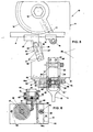
- the support (20) substantially consists of a "C" piece whose flat parallel arms (21, 21′) are an adequate distance apart, and extend from a solid piece provided with pin (22) whose axis is normal to the planes of said arms, and to be fastened to the top surface of boxlike main body (11) of minimachine (10).
- Pin (22) acts as a pivot for said support (20) so that the latter can freely rotate on it.
- the space between the inner parallel faces of arms (21, 21′) houses the portion of countermatrix projecting normal to groove (24′) and having a hole for pin (23) which allows some angular movement of countermatrix (24), said angular movement being restricted by projection (26) diverging nearly radially from said projecting portion and restricting the free rotation of countermatrix on pivot (23) by striking against a pin (27) located between arms (21, 21′) of support (20).
- a pin (25) projecting from the top surface of main body (11) to be struck against by the lower arm (21′) of the support.
- support (20) and associated countermatrix (24) will be further clarified here below to draw attention to the innovative features: - the support is constructed with predetermined shape and dimensions and allows any countermatrix (24) selected out of the available set as suitable to bend a pipe of a given diameter, to be mounted on it and operate; - the distance x (Figs.
- the motor (90) has been assumed to be fastened to wall (14) of the minimachine main body (11), through a supporting plate and pins and/or bolts driven in a direction parallel to the axes of shafts (43, 95) of the gear drive, as shown by dashed lines.
- the motor may be of the same type as used by the Applicant on other pipe bending machines, such as the one, for instance, mentioned in Patent No. 1.147.601 granted to the Applicant. It should, however, be specified, as a particularly important feature of this invention, that in the pipe-bending minimachine (10) this invention is related to, the motor carrying structure can be used also as a handle to be held and controlled by one hand, and that the motor shaft mounts a pinion gear (93) in mesh with gear wheel (94) which is one of those mounted on previously described shaft (95), the ratio between pinion (93) and gear wheel (94) being such as to provide a first amount of speed reduction to which, according to the schematic view of Fig. 4, is added that provided by meshed gear wheels (96, 54), and the final one provided by the meshed worm gear (42) and helical gear (41), in order to obtain the desired rotation speed of matrix-carrying shaft (15).
- Electric power is applied to the motor (90) through a cord (92).
- a conventional switch of for instance the toggle type (not shown), is a handy means allowing the operator to start the motor and manually control the machine (10) by one hand.
- Figures 5 and 6 schematically show the main details of the component parts of a device (60) used to actuate the gear drive previously described with reference to Fig. 4.
- such a manual control device must be easy to mount on main body (11) of pipe bending minimachine (10) and must control the rotation of shaft (95) in such a way as to drive in either the forward or reverse direction the matrix (16), in a manner similar to that previously described concerning the motor control.
- a device (60) which can be fastened to the fore face (14) of main body (11) for instance by means of pin (68) and fixing screw (69), since it is shaped like a channel section consisting of two flat parallel surfaces (60a, 60b) formed into a single unit and separated by a spacer (60c) to provide room for a ratchet wheel (61) whose axis of rotation is normal to said surfaces.
- a "C” projection (63), integral with said channel section, has a dovetail bottom wall for a hollow piece (64), shaped to match the dovetail, to slide in the vertical direction, and whose recess houses a pawl (67′) that engages the teeth of said ratchet wheel (61) to impart repeated consecutive intermittent angular movements to the ratchet wheel, and consequently to matrix (16) through said gear drive (40), the manual alternative movement of forklike lever (71) being allowed by a conventional spring (not shown) located between the lever and the fixed part of the machine so as to make is still easier to operate the machine by one hand and in any position during the bending operation.
- the long arm (73) of lever (71) can be locked to the opposed guide-support (74) by means of for instance a ring hook (75).
Landscapes
- Engineering & Computer Science (AREA)
- Mechanical Engineering (AREA)
- Bending Of Plates, Rods, And Pipes (AREA)
- Shaping Of Tube Ends By Bending Or Straightening (AREA)
Applications Claiming Priority (2)
| Application Number | Priority Date | Filing Date | Title |
|---|---|---|---|
| IT4820788 | 1988-07-19 | ||
| IT8848207A IT1224512B (it) | 1988-07-19 | 1988-07-19 | Mini-macchinetta curvatubi portatile a tre velocita' con possibile comando motorizzato o manuale e dispositivo di accoppiamento/disaccoppiamento automatico |
Publications (3)
| Publication Number | Publication Date |
|---|---|
| EP0352236A2 true EP0352236A2 (fr) | 1990-01-24 |
| EP0352236A3 EP0352236A3 (fr) | 1991-04-10 |
| EP0352236B1 EP0352236B1 (fr) | 1994-10-26 |
Family
ID=11265235
Family Applications (1)
| Application Number | Title | Priority Date | Filing Date |
|---|---|---|---|
| EP89830313A Expired - Lifetime EP0352236B1 (fr) | 1988-07-19 | 1989-07-07 | Mini machine portative pour le pliage de tubes à entraînement manuel ou motorisé et comportant un dispositif d'engagement/dégagement automatique |
Country Status (8)
| Country | Link |
|---|---|
| US (1) | US4986104A (fr) |
| EP (1) | EP0352236B1 (fr) |
| JP (1) | JPH07110380B2 (fr) |
| AT (1) | ATE113221T1 (fr) |
| CA (1) | CA1338925C (fr) |
| DE (1) | DE68919006D1 (fr) |
| ES (1) | ES2065411T3 (fr) |
| IT (1) | IT1224512B (fr) |
Cited By (4)
| Publication number | Priority date | Publication date | Assignee | Title |
|---|---|---|---|---|
| WO1992002338A1 (fr) * | 1990-07-27 | 1992-02-20 | Alex Lipp | Entrainement complementaire hydraulique ou pneumatique pour organes de formage de tole a main |
| EP0611611A1 (fr) * | 1993-02-19 | 1994-08-24 | Super-Ego Tools S.A. | Appareil électrique à couder les tubes |
| CN1059849C (zh) * | 1996-06-10 | 2000-12-27 | 沈忍源 | 弯曲成螺旋状管材的装置 |
| DE3903041C5 (de) * | 1989-02-02 | 2007-01-04 | REMS-WERK Christian Föll und Söhne GmbH & Co. | Handbiegegerät für Rohre, Stangen und dgl. |
Families Citing this family (15)
| Publication number | Priority date | Publication date | Assignee | Title |
|---|---|---|---|---|
| US5148695A (en) * | 1991-11-21 | 1992-09-22 | Ellis Harry S | Adjustable pipe and tubing bender |
| US5284040A (en) * | 1992-12-09 | 1994-02-08 | Emerson Electric Co. | Tube bending apparatus with stop and abutment means to set bend angle |
| US5327758A (en) * | 1993-06-28 | 1994-07-12 | Galan Jose M J | Pipe bending machines |
| US5469730A (en) * | 1994-10-13 | 1995-11-28 | Heaman; Norman L. | Pipe bending machine |
| US7162905B1 (en) | 2005-04-20 | 2007-01-16 | Mckay Acquisition, Inc. | Pipe bending pressure die with reversible exit block |
| US20080190164A1 (en) * | 2007-02-09 | 2008-08-14 | Boon Christopher J | Tube bending apparatus |
| CN201288800Y (zh) * | 2008-09-26 | 2009-08-12 | 广东省第二农机厂 | 弯曲机减速换向装置 |
| JP5530802B2 (ja) * | 2010-05-13 | 2014-06-25 | 三桜工業株式会社 | パイプの曲げ加工装置 |
| US8713984B2 (en) | 2011-01-13 | 2014-05-06 | David Wilson, Jr. | Multiple mode, bi-directional universal bending apparatus |
| US9003859B2 (en) * | 2011-04-01 | 2015-04-14 | University of Alaska Anchorage | Bending instrument and methods of using same |
| US9421596B2 (en) | 2014-04-16 | 2016-08-23 | University of Alaska Anchorage | Bending instrument and methods of using same |
| US20180078984A1 (en) * | 2015-04-02 | 2018-03-22 | Libero Angelo MASSARO | Multipurpose machine for bending metal tubes, both small and large |
| CN105867519B (zh) * | 2016-06-14 | 2017-12-01 | 中车株洲电力机车有限公司 | 一种司机控制器方向转换机构 |
| US11590548B2 (en) | 2019-09-11 | 2023-02-28 | Ecm Industries, Llc | Powered bender |
| AU2023231543A1 (en) | 2022-03-07 | 2024-09-26 | Ritchie Engineering Company, Inc. | Fast change fold-a-way cross bow swing arm multiple die tubing bender |
Family Cites Families (14)
| Publication number | Priority date | Publication date | Assignee | Title |
|---|---|---|---|---|
| US1309238A (en) * | 1919-07-08 | brinkman | ||
| US1272999A (en) * | 1917-06-25 | 1918-07-16 | Hayes Mfg Co | Edge-bending machine. |
| FR993643A (fr) * | 1948-08-27 | 1951-11-05 | Babcock & Wilcox France | Perfectionnements aux machines à plier les tubes et éléments analogues |
| US2822023A (en) * | 1955-11-25 | 1958-02-04 | Michael J Ahern | Ornamental iron scroll bender |
| US2986195A (en) * | 1956-07-09 | 1961-05-30 | Imp Eastman Corp | Tube bending machines |
| US3236082A (en) * | 1961-07-24 | 1966-02-22 | Crawford Fitting Co | Tube bending tools |
| US3285048A (en) * | 1963-01-18 | 1966-11-15 | Backer Elektro Varme Aktiebola | Machines for bending pipes, rods and bars |
| US3296849A (en) * | 1964-12-08 | 1967-01-10 | John G Pahl | Switch arm bending and punching machine |
| US3785190A (en) * | 1972-10-13 | 1974-01-15 | W Schall | High pressure portable tube bender |
| US3949584A (en) * | 1974-12-23 | 1976-04-13 | Greenlee Bros. & Co. | Bending apparatus having a roller support unit for E.M.T., conduit and thin wall tubing |
| SU725744A1 (ru) * | 1976-06-16 | 1980-04-05 | Предприятие П/Я В-8539 | Станок дл гибки труб |
| DE2904885A1 (de) * | 1979-02-09 | 1980-08-14 | Rothenberger Gmbh Co | Biegevorrichtung fuer metallrohre |
| US4532787A (en) * | 1981-03-16 | 1985-08-06 | C.M.L. Costruzioni Meccaniche Liri S.R.L. | Portable electromechanically-controlled pipe-bending apparatus |
| JPS61255721A (ja) * | 1985-05-08 | 1986-11-13 | Ishikawajima Harima Heavy Ind Co Ltd | 管の曲げ加工装置 |
-
1988
- 1988-07-19 IT IT8848207A patent/IT1224512B/it active
-
1989
- 1989-07-07 AT AT89830313T patent/ATE113221T1/de not_active IP Right Cessation
- 1989-07-07 DE DE68919006T patent/DE68919006D1/de not_active Expired - Lifetime
- 1989-07-07 EP EP89830313A patent/EP0352236B1/fr not_active Expired - Lifetime
- 1989-07-07 US US07/376,605 patent/US4986104A/en not_active Expired - Lifetime
- 1989-07-07 ES ES89830313T patent/ES2065411T3/es not_active Expired - Lifetime
- 1989-07-18 CA CA000605953A patent/CA1338925C/fr not_active Expired - Fee Related
- 1989-07-19 JP JP1187209A patent/JPH07110380B2/ja not_active Expired - Fee Related
Cited By (4)
| Publication number | Priority date | Publication date | Assignee | Title |
|---|---|---|---|---|
| DE3903041C5 (de) * | 1989-02-02 | 2007-01-04 | REMS-WERK Christian Föll und Söhne GmbH & Co. | Handbiegegerät für Rohre, Stangen und dgl. |
| WO1992002338A1 (fr) * | 1990-07-27 | 1992-02-20 | Alex Lipp | Entrainement complementaire hydraulique ou pneumatique pour organes de formage de tole a main |
| EP0611611A1 (fr) * | 1993-02-19 | 1994-08-24 | Super-Ego Tools S.A. | Appareil électrique à couder les tubes |
| CN1059849C (zh) * | 1996-06-10 | 2000-12-27 | 沈忍源 | 弯曲成螺旋状管材的装置 |
Also Published As
| Publication number | Publication date |
|---|---|
| EP0352236B1 (fr) | 1994-10-26 |
| JPH07110380B2 (ja) | 1995-11-29 |
| JPH0263612A (ja) | 1990-03-02 |
| DE68919006D1 (de) | 1994-12-01 |
| EP0352236A3 (fr) | 1991-04-10 |
| CA1338925C (fr) | 1997-02-25 |
| ATE113221T1 (de) | 1994-11-15 |
| US4986104A (en) | 1991-01-22 |
| ES2065411T3 (es) | 1995-02-16 |
| IT1224512B (it) | 1990-10-04 |
| IT8848207A0 (it) | 1988-07-19 |
Similar Documents
| Publication | Publication Date | Title |
|---|---|---|
| EP0352236A2 (fr) | Mini machine portative pour le pliage de tubes à entraînement manuel ou motorisé et comportant un dispositif d'engagement/dégagement automatique | |
| US3651569A (en) | Device for working a cylindrical work-piece | |
| US8689449B2 (en) | Powered tube cutter | |
| US3939924A (en) | Power torque wrench | |
| US4769911A (en) | Pipe cutting device | |
| US6887176B2 (en) | Torque transmission mechanisms and power tools having such torque transmission mechanisms | |
| US5022249A (en) | Portable manually-controlled three-speed pipe-bending machine | |
| JPH0671576A (ja) | 調節可能な出力トルクを有する二方式の回転動力工具 | |
| JPH0318971B2 (fr) | ||
| US5282704A (en) | Portable drilling apparatus | |
| JPH07290177A (ja) | 鉄筋結束機 | |
| US20240238960A1 (en) | Hand-held Pulling and Compressing Device | |
| US3988827A (en) | Small-size cutter | |
| CN109570290B (zh) | 用于建筑施工的管材加工平台及其管材弯管设备 | |
| JP3049494B2 (ja) | 可搬型電動式パイプベンダー | |
| CN110576224B (zh) | 一种钢管弯头定角度的切割装置 | |
| CN221269519U (zh) | 一种建筑钢筋弯曲装置 | |
| JP2813020B2 (ja) | パイプカッター | |
| CN108480789B (zh) | 液压式管道坡口机 | |
| CN213945825U (zh) | 一种工地打孔用钻头修磨的定位夹具 | |
| CN216660015U (zh) | 一种转向管柱用锁紧机构 | |
| JPS59124505A (ja) | 解放機構付き回転駆動伝達装置およびボ−ル盤等の自動送り装置 | |
| CN216098758U (zh) | 一种建筑工程用多功能锤 | |
| CN214551450U (zh) | 一种净水机 | |
| US4317280A (en) | Power feed apparatus for tools |
Legal Events
| Date | Code | Title | Description |
|---|---|---|---|
| PUAI | Public reference made under article 153(3) epc to a published international application that has entered the european phase |
Free format text: ORIGINAL CODE: 0009012 |
|
| AK | Designated contracting states |
Kind code of ref document: A2 Designated state(s): AT BE CH DE ES FR GB GR LI LU NL SE |
|
| 17P | Request for examination filed |
Effective date: 19900820 |
|
| PUAL | Search report despatched |
Free format text: ORIGINAL CODE: 0009013 |
|
| AK | Designated contracting states |
Kind code of ref document: A3 Designated state(s): AT BE CH DE ES FR GB GR LI LU NL SE |
|
| 17Q | First examination report despatched |
Effective date: 19920327 |
|
| GRAA | (expected) grant |
Free format text: ORIGINAL CODE: 0009210 |
|
| AK | Designated contracting states |
Kind code of ref document: B1 Designated state(s): AT BE CH DE ES FR GB GR LI LU NL SE |
|
| PG25 | Lapsed in a contracting state [announced via postgrant information from national office to epo] |
Ref country code: LI Effective date: 19941026 Ref country code: GR Free format text: LAPSE BECAUSE OF FAILURE TO SUBMIT A TRANSLATION OF THE DESCRIPTION OR TO PAY THE FEE WITHIN THE PRESCRIBED TIME-LIMIT Effective date: 19941026 Ref country code: CH Effective date: 19941026 |
|
| REF | Corresponds to: |
Ref document number: 113221 Country of ref document: AT Date of ref document: 19941115 Kind code of ref document: T |
|
| REF | Corresponds to: |
Ref document number: 68919006 Country of ref document: DE Date of ref document: 19941201 |
|
| PG25 | Lapsed in a contracting state [announced via postgrant information from national office to epo] |
Ref country code: SE Effective date: 19950126 |
|
| PG25 | Lapsed in a contracting state [announced via postgrant information from national office to epo] |
Ref country code: DE Effective date: 19950127 |
|
| REG | Reference to a national code |
Ref country code: CH Ref legal event code: PL |
|
| REG | Reference to a national code |
Ref country code: ES Ref legal event code: FG2A Ref document number: 2065411 Country of ref document: ES Kind code of ref document: T3 |
|
| ET | Fr: translation filed | ||
| PG25 | Lapsed in a contracting state [announced via postgrant information from national office to epo] |
Ref country code: LU Free format text: LAPSE BECAUSE OF NON-PAYMENT OF DUE FEES Effective date: 19950731 |
|
| PLBE | No opposition filed within time limit |
Free format text: ORIGINAL CODE: 0009261 |
|
| STAA | Information on the status of an ep patent application or granted ep patent |
Free format text: STATUS: NO OPPOSITION FILED WITHIN TIME LIMIT |
|
| 26N | No opposition filed | ||
| REG | Reference to a national code |
Ref country code: GB Ref legal event code: IF02 |
|
| PGFP | Annual fee paid to national office [announced via postgrant information from national office to epo] |
Ref country code: BE Payment date: 20020715 Year of fee payment: 14 |
|
| PGFP | Annual fee paid to national office [announced via postgrant information from national office to epo] |
Ref country code: AT Payment date: 20020724 Year of fee payment: 14 |
|
| PGFP | Annual fee paid to national office [announced via postgrant information from national office to epo] |
Ref country code: NL Payment date: 20020731 Year of fee payment: 14 |
|
| PG25 | Lapsed in a contracting state [announced via postgrant information from national office to epo] |
Ref country code: AT Free format text: LAPSE BECAUSE OF NON-PAYMENT OF DUE FEES Effective date: 20030707 |
|
| PG25 | Lapsed in a contracting state [announced via postgrant information from national office to epo] |
Ref country code: BE Free format text: LAPSE BECAUSE OF NON-PAYMENT OF DUE FEES Effective date: 20030731 |
|
| BERE | Be: lapsed |
Owner name: COSTRUZIONI MECCANICHE LIRI S.R.L. *CML Effective date: 20030731 |
|
| PG25 | Lapsed in a contracting state [announced via postgrant information from national office to epo] |
Ref country code: NL Free format text: LAPSE BECAUSE OF NON-PAYMENT OF DUE FEES Effective date: 20040201 |
|
| NLV4 | Nl: lapsed or anulled due to non-payment of the annual fee |
Effective date: 20040201 |
|
| PGFP | Annual fee paid to national office [announced via postgrant information from national office to epo] |
Ref country code: ES Payment date: 20040706 Year of fee payment: 16 |
|
| PGFP | Annual fee paid to national office [announced via postgrant information from national office to epo] |
Ref country code: GB Payment date: 20040712 Year of fee payment: 16 |
|
| PGFP | Annual fee paid to national office [announced via postgrant information from national office to epo] |
Ref country code: FR Payment date: 20040728 Year of fee payment: 16 |
|
| PG25 | Lapsed in a contracting state [announced via postgrant information from national office to epo] |
Ref country code: GB Free format text: LAPSE BECAUSE OF NON-PAYMENT OF DUE FEES Effective date: 20050707 |
|
| PG25 | Lapsed in a contracting state [announced via postgrant information from national office to epo] |
Ref country code: ES Free format text: LAPSE BECAUSE OF NON-PAYMENT OF DUE FEES Effective date: 20050708 |
|
| GBPC | Gb: european patent ceased through non-payment of renewal fee |
Effective date: 20050707 |
|
| PG25 | Lapsed in a contracting state [announced via postgrant information from national office to epo] |
Ref country code: FR Free format text: LAPSE BECAUSE OF NON-PAYMENT OF DUE FEES Effective date: 20060331 |
|
| REG | Reference to a national code |
Ref country code: FR Ref legal event code: ST Effective date: 20060331 |
|
| REG | Reference to a national code |
Ref country code: ES Ref legal event code: FD2A Effective date: 20050708 |