EP0352421A2 - Dispositif et procédé d'impression individuelle de cahiers pendant la sortie sur un transporteur d'une ligne de reliure - Google Patents
Dispositif et procédé d'impression individuelle de cahiers pendant la sortie sur un transporteur d'une ligne de reliure Download PDFInfo
- Publication number
- EP0352421A2 EP0352421A2 EP89108633A EP89108633A EP0352421A2 EP 0352421 A2 EP0352421 A2 EP 0352421A2 EP 89108633 A EP89108633 A EP 89108633A EP 89108633 A EP89108633 A EP 89108633A EP 0352421 A2 EP0352421 A2 EP 0352421A2
- Authority
- EP
- European Patent Office
- Prior art keywords
- signatures
- conveyor
- transfer
- binding line
- signature
- Prior art date
- Legal status (The legal status is an assumption and is not a legal conclusion. Google has not performed a legal analysis and makes no representation as to the accuracy of the status listed.)
- Withdrawn
Links
Images


Classifications
-
- B—PERFORMING OPERATIONS; TRANSPORTING
- B65—CONVEYING; PACKING; STORING; HANDLING THIN OR FILAMENTARY MATERIAL
- B65H—HANDLING THIN OR FILAMENTARY MATERIAL, e.g. SHEETS, WEBS, CABLES
- B65H5/00—Feeding articles separated from piles; Feeding articles to machines
- B65H5/30—Opening devices for folded sheets or signatures
- B65H5/305—Opening devices for folded sheets or signatures comprising rotary means for opening the folded sheets
- B65H5/307—Opening devices for folded sheets or signatures comprising rotary means for opening the folded sheets two opposite rotary means, both having gripping means
-
- B—PERFORMING OPERATIONS; TRANSPORTING
- B42—BOOKBINDING; ALBUMS; FILES; SPECIAL PRINTED MATTER
- B42C—BOOKBINDING
- B42C19/00—Multi-step processes for making books
- B42C19/04—Multi-step processes for making books starting with signatures
-
- B—PERFORMING OPERATIONS; TRANSPORTING
- B42—BOOKBINDING; ALBUMS; FILES; SPECIAL PRINTED MATTER
- B42C—BOOKBINDING
- B42C19/00—Multi-step processes for making books
- B42C19/08—Conveying between operating stations in machines
-
- B—PERFORMING OPERATIONS; TRANSPORTING
- B65—CONVEYING; PACKING; STORING; HANDLING THIN OR FILAMENTARY MATERIAL
- B65H—HANDLING THIN OR FILAMENTARY MATERIAL, e.g. SHEETS, WEBS, CABLES
- B65H3/00—Separating articles from piles
- B65H3/08—Separating articles from piles using pneumatic force
- B65H3/0808—Suction grippers
- B65H3/0816—Suction grippers separating from the top of pile
-
- B—PERFORMING OPERATIONS; TRANSPORTING
- B65—CONVEYING; PACKING; STORING; HANDLING THIN OR FILAMENTARY MATERIAL
- B65H—HANDLING THIN OR FILAMENTARY MATERIAL, e.g. SHEETS, WEBS, CABLES
- B65H3/00—Separating articles from piles
- B65H3/28—Separating articles from piles by screw or like separators
-
- B—PERFORMING OPERATIONS; TRANSPORTING
- B65—CONVEYING; PACKING; STORING; HANDLING THIN OR FILAMENTARY MATERIAL
- B65H—HANDLING THIN OR FILAMENTARY MATERIAL, e.g. SHEETS, WEBS, CABLES
- B65H3/00—Separating articles from piles
- B65H3/46—Supplementary devices or measures to assist separation or prevent double feed
- B65H3/50—Elements, e.g. fingers, plates, rollers, inserted or traversed between articles to be separated and remainder of the pile
-
- B—PERFORMING OPERATIONS; TRANSPORTING
- B65—CONVEYING; PACKING; STORING; HANDLING THIN OR FILAMENTARY MATERIAL
- B65H—HANDLING THIN OR FILAMENTARY MATERIAL, e.g. SHEETS, WEBS, CABLES
- B65H5/00—Feeding articles separated from piles; Feeding articles to machines
- B65H5/08—Feeding articles separated from piles; Feeding articles to machines by grippers, e.g. suction grippers
- B65H5/085—Feeding articles separated from piles; Feeding articles to machines by grippers, e.g. suction grippers by combinations of endless conveyors and grippers
-
- B—PERFORMING OPERATIONS; TRANSPORTING
- B65—CONVEYING; PACKING; STORING; HANDLING THIN OR FILAMENTARY MATERIAL
- B65H—HANDLING THIN OR FILAMENTARY MATERIAL, e.g. SHEETS, WEBS, CABLES
- B65H2301/00—Handling processes for sheets or webs
- B65H2301/40—Type of handling process
- B65H2301/43—Gathering; Associating; Assembling
- B65H2301/431—Features with regard to the collection, nature, sequence and/or the making thereof
- B65H2301/4311—Making personalised books or mail packets according to personal, geographic or demographic data
-
- B—PERFORMING OPERATIONS; TRANSPORTING
- B65—CONVEYING; PACKING; STORING; HANDLING THIN OR FILAMENTARY MATERIAL
- B65H—HANDLING THIN OR FILAMENTARY MATERIAL, e.g. SHEETS, WEBS, CABLES
- B65H2301/00—Handling processes for sheets or webs
- B65H2301/40—Type of handling process
- B65H2301/43—Gathering; Associating; Assembling
- B65H2301/435—Gathering; Associating; Assembling on collecting conveyor
- B65H2301/4351—Gathering; Associating; Assembling on collecting conveyor receiving articles astride thereon
-
- B—PERFORMING OPERATIONS; TRANSPORTING
- B65—CONVEYING; PACKING; STORING; HANDLING THIN OR FILAMENTARY MATERIAL
- B65H—HANDLING THIN OR FILAMENTARY MATERIAL, e.g. SHEETS, WEBS, CABLES
- B65H2301/00—Handling processes for sheets or webs
- B65H2301/40—Type of handling process
- B65H2301/45—Folding, unfolding
- B65H2301/453—Folding, unfolding opening folded material
- B65H2301/4531—Folding, unfolding opening folded material by opposite opening drums
-
- B—PERFORMING OPERATIONS; TRANSPORTING
- B65—CONVEYING; PACKING; STORING; HANDLING THIN OR FILAMENTARY MATERIAL
- B65H—HANDLING THIN OR FILAMENTARY MATERIAL, e.g. SHEETS, WEBS, CABLES
- B65H2301/00—Handling processes for sheets or webs
- B65H2301/50—Auxiliary process performed during handling process
- B65H2301/51—Modifying a characteristic of handled material
- B65H2301/511—Processing surface of handled material upon transport or guiding thereof, e.g. cleaning
- B65H2301/5111—Printing; Marking
Definitions
- the present invention generally relates to delivering signatures to a binding line conveyor and, more particularly, to an apparatus and method for individually printing signatures during such delivery.
- a typical operation utilizes a multitude of packer boxes each of which receives signatures seriatum from a signature supply means, opens each signature, and drops the signatures successively straddling a gathering chain that runs in front of the packer boxes and carries the complete collection of gathered signatures to the stitcher.
- packer boxes each of which receives signatures seriatum from a signature supply means, opens each signature, and drops the signatures successively straddling a gathering chain that runs in front of the packer boxes and carries the complete collection of gathered signatures to the stitcher.
- the present invention is directed to an apparatus and method for individually printing signatures during delivery to a binding line conveyor.
- the apparatus includes a feeding station for receiving a plurality of signatures to be delivered to the binding line conveyor. It also includes signature transfer means extending from the feeding station to the binding line conveyor whereby the signature transfer means is adapted to receive one signature at a time from the plurality of signatures at the feeding station and is also adapted to transfer the signatures to the binding line conveyor.
- the apparatus further includes means for individually printing in a direction perpendicular to the backbones of signatures during delivery to the binding line conveyor.
- the printing means includes at least one ink jet printer along the path of travel of signatures upstream of the point of transfer to the binding line conveyor.
- the feeding station receives signatures with the backbones extending perpendicular to the direction of travel of the signature transfer means. It is also advantageous for the signature transfer means to transfer signatures with the backbones remaining perpendicular to the direction of travel of the signature transfer means. Further, the printing means prints on signatures with the printing extending parallel to the direction of travel of the signature transfer means.
- the feeding station includes a feed conveyor for holding signatures in a stack with the backbones disposed on the feed conveyor.
- the signature transfer means also advantageously includes a transfer conveyor having a plurality of clips for gripping the backbones as the signatures are transferred to the binding line conveyor fore-edge first.
- the ink jet printer is appropriately disposed along the path of travel of the transfer conveyor for printing in a direction perpendicular to the backbones of signatures.
- the feeding station preferably includes means for separating one of the signatures at a time from the stack so that the backbones of separated ones of the signatures can be gripped by the clips of the transfer conveyor.
- the separating means includes a pair of disk blades mounted between the feed conveyor and the transfer conveyor with each of the disk blades having at least one signature separation slot about the perimeter thereof.
- the feed conveyor is preferably disposed in a generally horizontal plane
- the stack of signatures is disposed in a generally vertical orientation
- the disk blades are preferably mounted in a generally vertical plane for rotation in opposite directions.
- the separating means also preferivelyably includes reciprocating vacuum means operatively associated with the disk blades and disposed on the side of the disk blades opposite the stack of signatures for reciprocating movement so as to momentarily extend through the slots in the disk blades.
- the reciprocating vacuum means can reach out to grip one of the signatures and then pull the one of the signatures toward the disk blades for separation from the stack.
- the separating means preferably includes a pair of reciprocating governor pins operatively associated with the feed conveyor and a reciprocating restraining gate disposed between the governor pins to prevent bowing of the signatures so the clips on the transfer conveyor will only grip the backbone of a single one of the signatures at a time.
- the transfer conveyor includes a first portion running generally vertically upward in a plane perpendicular to and extending from the feed conveyor, a second portion running generally horizontal in a plane in spaced but parallel relation to the feed conveyor and a third portion running generally vertically downward in a plane perpendicular to and spaced from the feed conveyor.
- the transfer conveyor includes a supporting frame having inner and outer guides for the signatures operatively associated therewith, the inner and outer guides being laterally adjustable relative to the supporting frame in order to avoid interference with printing, and the signatures can follow a preselected inverted U-shaped travel path from the feed conveyor to the binding line conveyor.
- the present invention is directed to a method for individually printing signatures during delivery to a binding line conveyor which includes the step of providing a plurality of signatures to be delivered to the binding line conveyor. It also includes the step of transferring the signatures one at a time from the plurality of signatures to the binding line conveyor. The method further includes the step of individually printing in a direction perpendicular to the backbones of the signatures during delivery to the binding line conveyor, preferably by means of an ink jet printer.
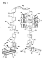
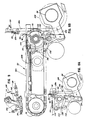
- the reference numeral 20 designates generally an apparatus for individually printing signatures 22 during delivery to a binding line conveyor 24.
- the apparatus 20 includes a feeding station 26 for receiving a plurality of signatures 22 to be delivered to the binding line conveyor 24. It also includes signature transfer means such as the transfer conveyor schematically illustrated and generally designated by reference numeral 28 extending from the feeding station 26 to the binding line conveyor 24 and adapted to receive one signature 22 at a time from the plurality of signatures at the feeding station 26 and to transfer the signatures 22 to the binding line conveyor 24.
- the apparatus also includes means as at 30 for individually printing on the signatures 22.
- the apparatus 20 is not only able to individually print on the signatures 22 but does so in a direction perpendicular to the backbones 22a during delivery to the binding line conveyor 24.
- the feeding station 26 receives the signatures 22 with the backbones 22a extending perpendicular to the direction of travel of the transfer conveyor 28. It will also be seen that the transfer conveyor 28 transfers the signatures 22 with backbones still extending perpendicular to the direction of travel of the transfer conveyor means 28. Further, the printing means as at 30 prints on the signatures 22 with the printing extending parallel to the direction of travel of the transfer conveyor 28.
- the feeding station 26 includes a feed conveyor 32 for holding the signatures 22 in a stack with the backbones 22a disposed on the feed conveyor 32.
- the transfer conveyor 28 has a plurality of clips 34 for gripping the backbones 22a as the signatures 22 are transferred to the binding line conveyor 24, fore-edge 22b first.
- the printing means as at 30 preferably includes at least one ink jet printer 36 along the path of travel of the transfer conveyor 28 upstream of the binding line conveyor 24.
- the feeding station 26 includes means for separating one of the signatures 22 at a time from the stack such that the backbones 22a of separated ones of the signatures 22 can be gripped by the clips 34 of the transfer conveyor 28.
- the separating means preferably includes a pair of disk blades 38 mounted between the feed conveyor 32 and the transfer conveyor 28 with each of the disk blades 38 including at least one signature separation slot 38a about the perimeter thereof.
- the feed conveyor 32 is advantageously disposed in a generally horizontal plane, the stack of signatures (see Fig. 1) is disposed in a generally vertical orientation, and the disk blades 38 are mounted in a generally vertical plane for rotation in opposite directions (see the arrows in Figs.
- the separating means also includes reciprocating vacuum suckers 40 operatively associated with the disk blades 38 and disposed on the side of the disk blades 38 opposite the stack of signatures 22. With this arrangement, the reciprocating vacuum suckers 40 are adapted to extend through the slots 38a in the disk blades 38 to grip one of the signatures 22 and to pull the one of the signatures 22 so gripped toward the disk blades 38 for separation from the stack.
- the separating means further includes a pair of reciprocating governor pins 42 operatively associated with the feed conveyor 32 such that the reciprocating vacuum suckers 40 are adapted to pull the backbone 22a of one of the signatures 22 across the governor pins 42 for separation from the stack. Still referring to Figs. 5, 8A and 8B, the separating means still further includes a reciprocating restraining gate 44 disposed between the governor pins 42 to prevent bowing of the signatures 22 to insure that each of the clips 34 on the transfer conveyor 28 only grips the backbone 22a of a single one of the signatures 22.
- the feeding station includes guide means for directing the stack of signatures 22 toward the transfer conveyor 28 in the form of a pair of guide plates 46 extending parallel to the feed conveyor 32 for cooperation with opposite sides of the stack of signatures 22.
- the disk blades 38 each include a pair of generally V-shaped signature separation slots 38a which are radially spaced so as to be diametrically opposed.
- the transfer conveyor 28 Extending from the disk blades 38, the transfer conveyor 28 includes a first portion 28a running generally vertically upward and away from the feed conveyor 32 in a plane generally parallel to the disk blades 38 and, as shown, the clips 34 are spaced along the transfer conveyor 28 and extend generally perpendicular to the direction of travel thereof.
- the separating means includes air means or nozzles 48 and air means or nozzles 49 extending diagonally inwardly toward the outside corners of the next signature 22 to be taken from the stack at the feeding station 26 for blowing the next one of the signatures 22 toward the disk blades 38 and reciprocating vacuum suckers 40 for separation of the one of the signatures 22 from the remainder of the stack.
- timing means such as a cam 50 operatively associated with a cam shaft 52 is provided to control at least the operation of the reciprocating vacuum suckers 40 relative to the disk blades 38 as will be described in greater detail hereinafter (see Fig. 6).
- the governor pins 42 are biased by means of a spring 54 in a direction toward the stack of signatures 22.
- the governor pins 42 are also pivotable away from the stack of signatures 22 responsive to an eccentric 56 (compare Figs. 8A and 8B).
- the eccentric 56 is operatively associated with the drive shaft 170 for the transfer conveyor 28 and controls the operation of the governor pins 42 during separation of one of the signatures 22 from the stack.
- the reciprocating restraining gate 44 is similarly moved into and out of the path of travel of the stack of signatures 22 on the feed conveyor 32 (again compare Figs. 8A and 8B). More particularly, the reciprocating restraining gate 44 moves out of the path of travel responsive to the eccentric 56 in a manner to be described in greater detail hereinafter.
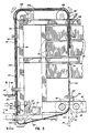
- the transfer conveyor 28 includes first portion 28a running generally vertically upward in a plane perpendicular to the feed conveyor 32, a second portion 28b running generally horizontal in a plane parallel to the feed conveyor 32, and a third portion 28c running generally vertically downward in a plane perpendicular to the feed conveyor 32.
- the transfer conveyor 28 includes a supporting frame generally designated 58, inner and outer guides 60 and 62 for the signatures 22 operatively associated with the supporting frame 58, and the ink jet printer or printers 36 are also operatively associated with the supporting frame 58.
- At least a pair of ink jet printers 36 are provided such that one of the printers is adapted to print on one side of the signatures 22 and the other of the printers is adapted to print on the other side of the signatures 22, and the inner and outer guides 60 and 62, as best shown in Figs. 2 and 3, extend along the first portion 28a of the transfer conveyor 28 as well as the second portion 28e thereof, while similar but thinner inner and outer guides 60′ and 62′ are provided along the third portion 28c of the transfer conveyor 28 to maximize the printing area on the signatures 22.
- the inner and outer guides 60 and 62 as well as 60′ and 62′ are laterally adjustable relative to the supporting frame 58, the transfer conveyor 28 is preferably a continuous chain, and the clips 34 release the signatures 22 after the signatures have traversed a preselected travel path.
- the preselected travel path is generally an inverted U-shaped path whereby the signatures first travel vertically upward, then horizontally across, and then vertically downward relative to the supporting frame 58.
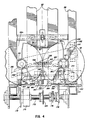
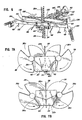
- the apparatus 20 preferably includes a delivery drum assembly 64 at the end of the U-shaped path of travel including a pair of drums 66 and 68 mounted for rotation in opposite directions.
- the drums 66 and 68 each include signature opening means or grippers 70 mounted for rotation therewith, and the signature opening means or grippers 70 are adapted to close on separate folios 22c and 22d of the signature 22 at a preselected point of travel and then to separate the folios to deposit the signatures 22 on the binding line conveyor 24.
- the grippers 70 and the clip 34 on the transfer conveyor 28 release the signature 22 at a preselected point of travel for deposit on the binding line conveyor 24.
- the feed conveyor 32 preferably comprises first and second conveyor portions 32a and 32b. More specifically, the conveyor portions 32a and 32b can comprise chains or belts which are driven by means of suitable sprockets 72,74 and 76,78, respectively, which are suitably interconnected for driven movement in indexed fashion as will be appreciated by referring to Figs. 8A and 8B. In this manner, the plurality of signatures 22 at the feeding station 26 are driven toward the rotating disk blades 38 on a demand basis.
- the feeding station 26 also preferably includes an adjustable guide plate 80 to be disposed over the fore-edges 22b of a plurality of the signatures 22.
- the adjustable guide plate 80 also serves to support a signature stack backing arm (not shown) which is connected to the retractable spring rollers 82 by means of retractable band springs (not shown) which can roll from and back onto the retractable spring rollers 82 whereby the signature stack backing arm can be placed behind a stack of signatures at the feeding station 26 during operation and can later be placed on the adjustable guide plate 80 in an out-of-the-way position when the apparatus 20 is not in use and when a stack of signatures is being loaded into the feeding station 26.
- the retractable spring rollers 82 are positioned so as not to interfere with directing the fore-edges 22b of the signatures 22 between the inner guides and the curved lower ends of the outer guides 62 after the clips 34 have gripped the backbones 22a of the signatures 22 and the transfer conveyor 28 has initiated movement of the signatures 22 from the feeding station 26 toward the binding line conveyor 24.
- the signature backing arm (not shown) serves as a retainer for the end of the stack of signatures 22 opposite the rotating disk blades 38 to maintain the stack of signatures 22 in a generally vertical or upright orientation.
- FIG. 2 and 5 Other details of the invention illustrated in Figs. 2 and 5 include angularly disposed knife blades 84 adjacent the rotating disk blades 38. These knife blades 84 are adapted to cooperate with the remainder of the means for separating one of the signatures 22 at a time from the stack of signatures by retaining the next adjacent of the signatures in position while the reciprocating vacuum suckers 40 pull the signature to be separated into position for separation by the rotating disk blades 38.
- the positioning of the knife blades 84 is made adjustable in any conventional manner.
- the apparatus 20 can suitivelyably be mounted on a standard packer box base 86 making it possible to efficiently replace any given packer box in a binding line.
- the apparatus 20 is particularly adapted, of course, for use where the signature to be delivered at that point in the binding line is to be individually printed.
- the apparatus 20 can simply be used at all times as a packer box, even when no printing on internal signatures is desired, by simply replacing a conventional packer box.
- the apparatus 20 will optionally include a control box 8B which will, of course, have suitable switches, dials and the like (as shown) to serve as a local disabilizing means for interrupting operation of the apparatus 20 including the source of air, the vacuum, and the drive means.
- a control box 8B which will, of course, have suitable switches, dials and the like (as shown) to serve as a local disabilizing means for interrupting operation of the apparatus 20 including the source of air, the vacuum, and the drive means.
- the source of air, the vacuum, the drive means, etc. will normally be operated by a common drive means or drive shaft for the entire bindery line in order to ensure synchronous operation and this will, in turn, normally control operation of all of the moving components by means of shafts, gears, belts, pulleys, chains and the like.
- these will include the belt 90 and pulleys 92, 94, 96 and 98 provided to control operation of the delivery drum assembly 64, the transfer conveyor or chain 28 and the sprockets 100, 102, 104 and 106, and the drive chain 108 and the sprockets 110, 112, 114 and 116.
- the reciprocating vacuum suckers 40 are preferably mounted on a header 118 carried by an arm assembly 120 having a cam follower 124 at the end remote from the header 118 where the arm assembly 120 is biased by means of a spring 122 toward the cam 50 and cam shaft 52. It will be seen that the cam follower 124 remote from the header 118 cooperates with the cam 50 and the spring 122 to impart the reciprocating motion to the vacuum suckers 40 as suggested by the arrow adjacent the arm assembly 120.
- the reciprocating vacuum suckers 40 each include a vacuum line 126 in communication with a source of vacuum controlled by a valve so as to release the signatures after they have been gripped by the clips 34 so the transfer conveyor 28 can carry the signatures 22 away from the feed station 26 (compare Figs. 7A and 7B).
- the eccentric 56 causes an arm 128 to reciprocate as the drive shaft 170 rotates and this, in turn, causes a first rocker arm 130 to rotate first in one direction and then the other which causes a second rocker arm 132 to impart reciprocating up and down movement to the restraining gate 44 through the pivotal ly mounted restraining gate bracket 134 and the connecting link 136.
- the rocker arm 130 acts against a finger 138 in opposition to the spring 54 to impart reciprocating movement to the governor pins 42.
- the sprocket 106 carries a trip lever 140 adapted to cause the clips 34 to open at a point after they have been closed against and firmly gripped the backbones 22a of the signatures 22.
- the clips 34 are maintained in this position until they receive the next of the signatures 22 at the feeding station 26.
- the clips 34 are closed by over center snap action into the closed position whereby a ball plunger type spring detent is used to hold the clips 34 in the closed position until they are once again opened by means of the trip lever 140.
- a signature 22 approaches the drums 66 and 68, the grippers 70 are caused to close on the separate folios 22c and 22d of the signatures 22 by means of springs 144. Then, as the drums 66 and 68 continue to rotate (see Figs. 11c and 11d), a cam such as 146 engages a cam follower such as 148 to cause the grippers 70 to open against the biasing force of the springs 144 to thereby release the signatures 22 after they have been pulled from the clips 34 by the grippers 70 such that the signatures 22 can then drop onto the binding line conveyor 24. With this arrangement, the signatures 22 can be opened sufficiently to ensure that they are properly deposited on the binding line conveyor 24.
- a gear box 150 is provided to transmit rotary motion of the shaft 52 to the rotating disk blades 38 by means of the drive chain 108 and the sprockets 110, 112, 114 and 116.
- an adjustable mounting bracket 152 for the sprocket 110 there is an adjustable mounting bracket 152 for the sprocket 110, a fixed mounting bracket 154 for the sprocket 112, and an adjustable mounting bracket 156 for the sprocket 116.
- the exact relative positioning of the sprockets 110, 112, 114 and 116 can be varied to adjust the position of the rotating disk blades 38 to handle different size signatures.
- this is accomplished by means of a pair of blocks 158 disposed on a threaded shaft 160.
- the mounting brackets 154 and 156 are secured to the threaded blocks 158 by means of fasteners such as bolts 162 and, as previously described, the mounting bracket 154 is fixedly mounted after adjustment of the position of the block 158 to which it is attached along the longitudinal extent of the threaded rod 160, by means of a bolt 164 whereas the mounting bracket 156 is positioned by means of the bolt 166 which is disposed in a slot 168 in the mounting bracket 156.
- the cam 50 is mounted on the shaft 52. These are both driven by means of a shaft 170 which carries a drive sprocket 172, a clutch 174, the sprocket 106 for the transfer conveyor chain 28 and eccentric 176, and sprockets 178 and 180 about which a chain 182 passes to drive shaft 52.
- the drive sprocket 172 is connected by a chain (not shown) to the main drive shaft of the entire bindery line.
- the guide wheels 183 are provided at the top and bottom of the arm assembly 120. It will be appreciated that the guide wheels 183 control the path of reciprocating movement of the arm 120 and the header 118 which, in turn, controls the movement of the reciprocating vacuum suckers 40 Also shown in Fig. 3 is the cam 50 carried by the shaft 52 and one of an opposing pair of horizontally disposed side guide wheels 184 for the arm assembly 120.
- a plate 186 is mounted to the outer guide 62 by means of screws as at 188.
- This plate 186 supports a pair of trip levers 190 which act against the camming surfaces 34a (see Fig. 9) to again close the clips 34 just as they receive the backbone 22a of one of the signatures 22.
- the trip lever 140 also acts against the same camming surfaces 34a of the clip 34 although in the opposite direction to open the clips 34 before they enter the region of the feeding station 26.
- the inner and outer guides 60′ and 62′ are not only thinner than the inner and outer guides 60 and 62 but are also adjustable. This adjustability is accomplished by means of collars 192 adjacent to the top and bottom of the third portion 28c of the transfer conveyor 28 whereby the guides 60′ and 62′ are integrally associated with the collars 192 which, in turn, are supported on rods 194. By providing the collars 192 with set screws (not shown), adjustment of the position of the inner and outer guide 60′ and 62′ is rendered an easy task.
- the lower set of rods 192 also serve to support the cams 146 by means of collars 194 and arms 196 extending therefrom.
- the integral arms 196 preferably include slots 198.
- the drums 66 and 68 are mounted on respective shafts 202 and 204 for rotational movement in opposite directions. These drums 66 and 68 are driven in conventional fashion by means of timing belt sprockets 92, 94, 96 and 98 which are driven by means of the timing belt 90 through the movement of the sprocket 104 of the transfer conveyor 28. In this fashion, the movement of the operating components of the entire apparatus 20 is provided in a controlled and synchronized fashion.
- the rods 206 are threadably adjustable. It will also be appreciated that they are provided for adjusting the force exerted by the springs 54 on the governor pins 42. In this manner, it is possible to control the action of the governor pins 42 in a precise fashion.
- saw blades 208 are provided on opposite sides of the feeding station 26 closely adjacent to governor pins 42.
- the saw blades 208 are curved upward and forwardly toward the transfer conveyor 28 which serves to ramp up the next signature to be taken by one of the clips 34. By so doing, the curl can be taken out of the signatures 22 at the backbones 22a in cooperation with the action of the restraining gate 44.
- the apparatus 20 will include a vacuum valve operatively associated with the drive shaft. It will include means for shutting off the vacuum between each cycle and, if desired, selectively skipping a signature as one of the clips 34 passes by the feeding station 26.
- the apparatus 20 may suitably include standard detectors e. g., missing signature detectors, choke up detectors, etc.
- the present invention makes it possible to eliminate the stream feeder by feeding directly from the bundle or stack.
Landscapes
- Engineering & Computer Science (AREA)
- Mechanical Engineering (AREA)
- Separation, Sorting, Adjustment, Or Bending Of Sheets To Be Conveyed (AREA)
- Particle Formation And Scattering Control In Inkjet Printers (AREA)
- Folding Of Thin Sheet-Like Materials, Special Discharging Devices, And Others (AREA)
Applications Claiming Priority (2)
| Application Number | Priority Date | Filing Date | Title |
|---|---|---|---|
| US22433288A | 1988-07-26 | 1988-07-26 | |
| US224332 | 1988-07-26 |
Publications (2)
| Publication Number | Publication Date |
|---|---|
| EP0352421A2 true EP0352421A2 (fr) | 1990-01-31 |
| EP0352421A3 EP0352421A3 (fr) | 1990-08-29 |
Family
ID=22840202
Family Applications (1)
| Application Number | Title | Priority Date | Filing Date |
|---|---|---|---|
| EP89108633A Withdrawn EP0352421A3 (fr) | 1988-07-26 | 1989-05-12 | Dispositif et procédé d'impression individuelle de cahiers pendant la sortie sur un transporteur d'une ligne de reliure |
Country Status (3)
| Country | Link |
|---|---|
| US (1) | US5005815A (fr) |
| EP (1) | EP0352421A3 (fr) |
| JP (1) | JPH0280296A (fr) |
Cited By (5)
| Publication number | Priority date | Publication date | Assignee | Title |
|---|---|---|---|---|
| EP0416489A3 (en) * | 1989-09-05 | 1991-06-12 | Am International Incorporated | Collator with printer |
| EP0627376A1 (fr) * | 1993-05-03 | 1994-12-07 | R.R. DONNELLEY & SONS COMPANY | Dispositif perfectionné d'alimentation en cahiers pour ligne de reliure |
| WO1998003422A1 (fr) * | 1996-07-19 | 1998-01-29 | Ferag Ag | Procede et dispositif pour le transport de produits d'imprimerie |
| EP1655244A3 (fr) * | 2004-09-15 | 2006-06-21 | Ferag AG | Procédé et dispositif de séparation d'articles plats d'une pile horizontale |
| EP2133295A1 (fr) * | 2008-06-12 | 2009-12-16 | Müller Martini Holding AG | Dispositif et procédé destinés à extraire des produits d'impression plats d'une pile et à les transmettre à un dispositif de transport déroulant |
Families Citing this family (19)
| Publication number | Priority date | Publication date | Assignee | Title |
|---|---|---|---|---|
| US5203549A (en) * | 1989-09-05 | 1993-04-20 | Am International Incorporated | Collator with printer having inclined printing path and displaceable conveyor belts to expose printing surface |
| US5114129A (en) * | 1990-12-14 | 1992-05-19 | R. R. Donnelley & Sons Company | Signature feeding apparatus |
| US5143362A (en) * | 1991-07-15 | 1992-09-01 | Moore Business Forms, Inc. | Publication personalization |
| US5174556A (en) * | 1991-11-20 | 1992-12-29 | Xerox Corporation | Finisher with binder printing |
| DE59306556D1 (de) * | 1992-04-06 | 1997-07-03 | Ferag Ag | Verfahren und Vorrichtung zum Öffnen von gefalteten Druckereiprodukten |
| US5819663A (en) * | 1995-09-06 | 1998-10-13 | Quad/Tech, Inc. | Gripper conveyor with preliminary ink jet |
| EP0893385B1 (fr) * | 1997-07-22 | 2001-09-05 | Ferag AG | Dispositif pour traiter des produits imprimés |
| US6267366B1 (en) * | 1999-10-25 | 2001-07-31 | Quad/Graphics, Inc. | Apparatus and method of delivering signatures to a binding line |
| GB2356189B (en) * | 1999-11-11 | 2004-01-14 | Ibis Integrated Bindery System | Book bindery and trimming apparatus |
| EP1259449B1 (fr) * | 2000-03-03 | 2005-09-14 | Ferag AG | Procede et dispositif permettant de deposer des produits plats |
| US6623000B2 (en) | 2001-06-15 | 2003-09-23 | Prim Hall Enterprises Inc. | Apparatus and method for separating sheet material by means of a reciprocating disk separator |
| US6981830B2 (en) * | 2002-02-28 | 2006-01-03 | Hewlett-Packard Development Company, L.P. | Pivotable collecting device |
| US7033123B2 (en) * | 2002-02-28 | 2006-04-25 | Hewlett-Packard Development Company, L.P. | Booklet maker |
| US6893016B2 (en) * | 2002-03-29 | 2005-05-17 | Graphic Management Associates, Inc. | Print on demand inserter |
| US7325375B2 (en) * | 2004-06-23 | 2008-02-05 | Quad/Graphics, Inc. | Selective product inserter apparatus and process |
| EP1886832A1 (fr) * | 2006-08-10 | 2008-02-13 | Müller Martini Holding AG | Procédé et dispositif pour produire des articles imprimés formées de produits de l'imprimerie reliés par adhésif |
| EP1886833A1 (fr) * | 2006-08-10 | 2008-02-13 | Müller Martini Holding AG | Procédé et dispositif de fabrication d'un objet imprimé relié par adhésif à partir de plusieurs produits imprimés |
| ATE495024T1 (de) * | 2008-10-02 | 2011-01-15 | Mueller Martini Holding Ag | Verfahren zur herstellung von klebegebundenen buchblocks, sowie vorrichtung zur durchführung des verfahrens |
| EP2233313A1 (fr) * | 2009-03-13 | 2010-09-29 | Müller Martini Holding AG | Procédé et dispositifs de fabrication de résultats d'impression constitués de plusieurs produits d'impression formés et reliés à l'aide de colle |
Family Cites Families (15)
| Publication number | Priority date | Publication date | Assignee | Title |
|---|---|---|---|---|
| US2749117A (en) * | 1953-03-27 | 1956-06-05 | Hobson Miller Machinery Inc | Machine for handling cards and the like |
| DE1105885B (de) * | 1956-06-25 | 1961-05-04 | Mead Corp | Blattvereinzelungsvorrichtung |
| US3172655A (en) * | 1962-01-04 | 1965-03-09 | Berkley Machine Co | Mechanism for removing blanks or sheets from a stack |
| US3819173A (en) * | 1971-09-01 | 1974-06-25 | Harris Intertype Corp | Method and apparatus for producing magazines or the like |
| US4121818A (en) * | 1976-07-28 | 1978-10-24 | R. R. Donnelley & Sons Co. | Signature collating and binding system |
| US4283731A (en) * | 1980-04-22 | 1981-08-11 | The Mead Corporation | Ink jet printing apparatus |
| US4585220A (en) * | 1983-08-23 | 1986-04-29 | Bell & Howell Company | Method of operating insertion machine and printer with control signals stored on searchable medium |
| US4500083A (en) * | 1983-12-08 | 1985-02-19 | R. R. Donnelley & Sons Company | Collating and binding system and method with postage indication |
| US4674052A (en) * | 1983-12-08 | 1987-06-16 | R. R. Donnelley & Sons Company | Collating and binding system and method with postage indication |
| US4555101A (en) * | 1984-03-13 | 1985-11-26 | Stobb, Inc. | Method and apparatus for separating signatures from a stack |
| DE3421208A1 (de) * | 1984-06-07 | 1985-12-12 | Mohndruck Graphische Betriebe GmbH, 4830 Gütersloh | Verfahren und vorrichtung zum innenadressieren von insbesondere rueckstichbroschuren wie z. b. von zeitschriften und prospekten o.dgl. |
| US4582312A (en) * | 1984-09-07 | 1986-04-15 | Bell & Howell Company | Printing apparatus for insertion machine |
| CH665411A5 (de) * | 1985-02-07 | 1988-05-13 | Grapha Holding Ag | Zusammentragmaschine. |
| US4789147A (en) * | 1986-04-21 | 1988-12-06 | R. R. Donnelley & Sons Company | System and method for selective assembly and imaging of books |
| US4778167A (en) * | 1986-12-30 | 1988-10-18 | Alden Press, Inc. | Collating system including caliper |
-
1989
- 1989-05-12 EP EP89108633A patent/EP0352421A3/fr not_active Withdrawn
- 1989-07-25 JP JP1190714A patent/JPH0280296A/ja active Pending
-
1990
- 1990-02-20 US US07/483,333 patent/US5005815A/en not_active Expired - Lifetime
Cited By (6)
| Publication number | Priority date | Publication date | Assignee | Title |
|---|---|---|---|---|
| EP0416489A3 (en) * | 1989-09-05 | 1991-06-12 | Am International Incorporated | Collator with printer |
| EP0627376A1 (fr) * | 1993-05-03 | 1994-12-07 | R.R. DONNELLEY & SONS COMPANY | Dispositif perfectionné d'alimentation en cahiers pour ligne de reliure |
| WO1998003422A1 (fr) * | 1996-07-19 | 1998-01-29 | Ferag Ag | Procede et dispositif pour le transport de produits d'imprimerie |
| US6264192B1 (en) | 1996-07-19 | 2001-07-24 | Ferag Ag | Process and apparatus for conveying pressroom products |
| EP1655244A3 (fr) * | 2004-09-15 | 2006-06-21 | Ferag AG | Procédé et dispositif de séparation d'articles plats d'une pile horizontale |
| EP2133295A1 (fr) * | 2008-06-12 | 2009-12-16 | Müller Martini Holding AG | Dispositif et procédé destinés à extraire des produits d'impression plats d'une pile et à les transmettre à un dispositif de transport déroulant |
Also Published As
| Publication number | Publication date |
|---|---|
| US5005815A (en) | 1991-04-09 |
| JPH0280296A (ja) | 1990-03-20 |
| EP0352421A3 (fr) | 1990-08-29 |
Similar Documents
| Publication | Publication Date | Title |
|---|---|---|
| EP0352421A2 (fr) | Dispositif et procédé d'impression individuelle de cahiers pendant la sortie sur un transporteur d'une ligne de reliure | |
| CA1097382A (fr) | Machine d'acquisition de signatures | |
| US4582312A (en) | Printing apparatus for insertion machine | |
| JP2649417B2 (ja) | 印刷物の収集、まとめおよび差込み合せを行なう装置 | |
| US4396336A (en) | Apparatus for feeding lifts of limp sheets | |
| CA1264167A (fr) | Methode et dispositif pour ouvrir des imprimes plies hors axe | |
| US4720960A (en) | Sheet collating apparatus and method | |
| JPS6123080A (ja) | 折丁を丁合いする方法並びに装置 | |
| EP0384119B1 (fr) | Dispositif et procédé pour former des assemblages d'un matériau en feuille | |
| US5921538A (en) | Apparatus and method for combined gathering and binding of sheet like articles | |
| GB1031848A (en) | Improvements in or relating to stacking copies of folded newspapers, periodicals or other similar articles | |
| EP0472900A1 (fr) | Appareil et procédé pour imprimer individuellement des cahiers durant leur délivrance vers une ligne de reliure | |
| EP0426256A1 (fr) | Appareil pour l'alimentation contrôlée de produits en forme de feuilles dans une machine de collationnement ou d'emballage | |
| US2845264A (en) | Signature feeding and opening mechanism | |
| US5067700A (en) | Method and apparatus for attaching inserts to moving sheets | |
| US4106762A (en) | High speed insert handling mechanism and method | |
| US6623000B2 (en) | Apparatus and method for separating sheet material by means of a reciprocating disk separator | |
| US3692300A (en) | Feeder and folder arrangement for signature gathering machine | |
| EP0306490A1 (fr) | Procede pour assembler des cahiers et machine d'assemblage permettant la mise en o euvre du procede | |
| US4383683A (en) | Apparatus for separating the bottom sheet of a stack or sheets | |
| EP0232374A1 (fr) | Dispositif de transfert de feuilles | |
| GB2304699A (en) | Sheet feeding processes | |
| US6581753B1 (en) | Transport apparatus | |
| EP0379879A2 (fr) | Appareil et procédé pour imprimer individuellement des cahiers durant leur délivrance vers une ligne de reliure | |
| US4305655A (en) | Duplex printer and method of printing |
Legal Events
| Date | Code | Title | Description |
|---|---|---|---|
| PUAI | Public reference made under article 153(3) epc to a published international application that has entered the european phase |
Free format text: ORIGINAL CODE: 0009012 |
|
| AK | Designated contracting states |
Kind code of ref document: A2 Designated state(s): CH DE FR GB IT LI |
|
| PUAL | Search report despatched |
Free format text: ORIGINAL CODE: 0009013 |
|
| AK | Designated contracting states |
Kind code of ref document: A3 Designated state(s): CH DE FR GB IT LI |
|
| 17P | Request for examination filed |
Effective date: 19901203 |
|
| 17Q | First examination report despatched |
Effective date: 19920918 |
|
| STAA | Information on the status of an ep patent application or granted ep patent |
Free format text: STATUS: THE APPLICATION HAS BEEN WITHDRAWN |
|
| 18W | Application withdrawn |
Withdrawal date: 19930212 |