EP0352468A2 - Procédé de fabrication d'une plaque à tuyères pour une tête d'imprimante à jet d'encre - Google Patents
Procédé de fabrication d'une plaque à tuyères pour une tête d'imprimante à jet d'encre Download PDFInfo
- Publication number
- EP0352468A2 EP0352468A2 EP89111168A EP89111168A EP0352468A2 EP 0352468 A2 EP0352468 A2 EP 0352468A2 EP 89111168 A EP89111168 A EP 89111168A EP 89111168 A EP89111168 A EP 89111168A EP 0352468 A2 EP0352468 A2 EP 0352468A2
- Authority
- EP
- European Patent Office
- Prior art keywords
- recording head
- ink jet
- recording apparatus
- orifice plate
- positioning
- Prior art date
- Legal status (The legal status is an assumption and is not a legal conclusion. Google has not performed a legal analysis and makes no representation as to the accuracy of the status listed.)
- Granted
Links
- 238000004519 manufacturing process Methods 0.000 title description 6
- 238000007599 discharging Methods 0.000 claims abstract description 12
- 239000007788 liquid Substances 0.000 claims description 13
- 238000000206 photolithography Methods 0.000 claims description 4
- 230000000694 effects Effects 0.000 claims description 3
- 238000010276 construction Methods 0.000 description 13
- 238000000034 method Methods 0.000 description 10
- 230000000875 corresponding effect Effects 0.000 description 7
- 230000008569 process Effects 0.000 description 6
- 230000015572 biosynthetic process Effects 0.000 description 4
- 238000003754 machining Methods 0.000 description 4
- PXHVJJICTQNCMI-UHFFFAOYSA-N Nickel Chemical compound [Ni] PXHVJJICTQNCMI-UHFFFAOYSA-N 0.000 description 3
- 238000002474 experimental method Methods 0.000 description 3
- 239000000463 material Substances 0.000 description 3
- 239000011347 resin Substances 0.000 description 3
- 229920005989 resin Polymers 0.000 description 3
- VYPSYNLAJGMNEJ-UHFFFAOYSA-N Silicium dioxide Chemical compound O=[Si]=O VYPSYNLAJGMNEJ-UHFFFAOYSA-N 0.000 description 2
- 238000005530 etching Methods 0.000 description 2
- 239000012530 fluid Substances 0.000 description 2
- 239000010410 layer Substances 0.000 description 2
- 239000007769 metal material Substances 0.000 description 2
- 238000004080 punching Methods 0.000 description 2
- 239000000758 substrate Substances 0.000 description 2
- 230000004888 barrier function Effects 0.000 description 1
- 238000009835 boiling Methods 0.000 description 1
- 230000008859 change Effects 0.000 description 1
- 229910052681 coesite Inorganic materials 0.000 description 1
- 230000008602 contraction Effects 0.000 description 1
- 229910052906 cristobalite Inorganic materials 0.000 description 1
- 230000007850 degeneration Effects 0.000 description 1
- 239000011521 glass Substances 0.000 description 1
- 229910052759 nickel Inorganic materials 0.000 description 1
- 229920002120 photoresistant polymer Polymers 0.000 description 1
- 230000000644 propagated effect Effects 0.000 description 1
- 239000011241 protective layer Substances 0.000 description 1
- 238000001454 recorded image Methods 0.000 description 1
- 230000009467 reduction Effects 0.000 description 1
- 238000010008 shearing Methods 0.000 description 1
- 239000000377 silicon dioxide Substances 0.000 description 1
- 235000012239 silicon dioxide Nutrition 0.000 description 1
- 125000006850 spacer group Chemical group 0.000 description 1
- 229910001220 stainless steel Inorganic materials 0.000 description 1
- 239000010935 stainless steel Substances 0.000 description 1
- 229910052682 stishovite Inorganic materials 0.000 description 1
- 238000004381 surface treatment Methods 0.000 description 1
- 229910052905 tridymite Inorganic materials 0.000 description 1
Images


Classifications
-
- B—PERFORMING OPERATIONS; TRANSPORTING
- B41—PRINTING; LINING MACHINES; TYPEWRITERS; STAMPS
- B41J—TYPEWRITERS; SELECTIVE PRINTING MECHANISMS, i.e. MECHANISMS PRINTING OTHERWISE THAN FROM A FORME; CORRECTION OF TYPOGRAPHICAL ERRORS
- B41J2/00—Typewriters or selective printing mechanisms characterised by the printing or marking process for which they are designed
- B41J2/005—Typewriters or selective printing mechanisms characterised by the printing or marking process for which they are designed characterised by bringing liquid or particles selectively into contact with a printing material
- B41J2/01—Ink jet
- B41J2/135—Nozzles
- B41J2/16—Production of nozzles
- B41J2/1621—Manufacturing processes
- B41J2/1631—Manufacturing processes photolithography
-
- B—PERFORMING OPERATIONS; TRANSPORTING
- B41—PRINTING; LINING MACHINES; TYPEWRITERS; STAMPS
- B41J—TYPEWRITERS; SELECTIVE PRINTING MECHANISMS, i.e. MECHANISMS PRINTING OTHERWISE THAN FROM A FORME; CORRECTION OF TYPOGRAPHICAL ERRORS
- B41J2/00—Typewriters or selective printing mechanisms characterised by the printing or marking process for which they are designed
- B41J2/005—Typewriters or selective printing mechanisms characterised by the printing or marking process for which they are designed characterised by bringing liquid or particles selectively into contact with a printing material
- B41J2/01—Ink jet
- B41J2/135—Nozzles
- B41J2/16—Production of nozzles
- B41J2/162—Manufacturing of the nozzle plates
-
- B—PERFORMING OPERATIONS; TRANSPORTING
- B41—PRINTING; LINING MACHINES; TYPEWRITERS; STAMPS
- B41J—TYPEWRITERS; SELECTIVE PRINTING MECHANISMS, i.e. MECHANISMS PRINTING OTHERWISE THAN FROM A FORME; CORRECTION OF TYPOGRAPHICAL ERRORS
- B41J2/00—Typewriters or selective printing mechanisms characterised by the printing or marking process for which they are designed
- B41J2/005—Typewriters or selective printing mechanisms characterised by the printing or marking process for which they are designed characterised by bringing liquid or particles selectively into contact with a printing material
- B41J2/01—Ink jet
- B41J2/135—Nozzles
- B41J2/16—Production of nozzles
- B41J2/1621—Manufacturing processes
- B41J2/1626—Manufacturing processes etching
-
- B—PERFORMING OPERATIONS; TRANSPORTING
- B41—PRINTING; LINING MACHINES; TYPEWRITERS; STAMPS
- B41J—TYPEWRITERS; SELECTIVE PRINTING MECHANISMS, i.e. MECHANISMS PRINTING OTHERWISE THAN FROM A FORME; CORRECTION OF TYPOGRAPHICAL ERRORS
- B41J2/00—Typewriters or selective printing mechanisms characterised by the printing or marking process for which they are designed
- B41J2/005—Typewriters or selective printing mechanisms characterised by the printing or marking process for which they are designed characterised by bringing liquid or particles selectively into contact with a printing material
- B41J2/01—Ink jet
- B41J2/135—Nozzles
- B41J2/16—Production of nozzles
- B41J2/1621—Manufacturing processes
- B41J2/1632—Manufacturing processes machining
-
- B—PERFORMING OPERATIONS; TRANSPORTING
- B41—PRINTING; LINING MACHINES; TYPEWRITERS; STAMPS
- B41J—TYPEWRITERS; SELECTIVE PRINTING MECHANISMS, i.e. MECHANISMS PRINTING OTHERWISE THAN FROM A FORME; CORRECTION OF TYPOGRAPHICAL ERRORS
- B41J2/00—Typewriters or selective printing mechanisms characterised by the printing or marking process for which they are designed
- B41J2/005—Typewriters or selective printing mechanisms characterised by the printing or marking process for which they are designed characterised by bringing liquid or particles selectively into contact with a printing material
- B41J2/01—Ink jet
- B41J2/135—Nozzles
- B41J2/16—Production of nozzles
- B41J2/1621—Manufacturing processes
- B41J2/1637—Manufacturing processes molding
-
- B—PERFORMING OPERATIONS; TRANSPORTING
- B41—PRINTING; LINING MACHINES; TYPEWRITERS; STAMPS
- B41J—TYPEWRITERS; SELECTIVE PRINTING MECHANISMS, i.e. MECHANISMS PRINTING OTHERWISE THAN FROM A FORME; CORRECTION OF TYPOGRAPHICAL ERRORS
- B41J2/00—Typewriters or selective printing mechanisms characterised by the printing or marking process for which they are designed
- B41J2/005—Typewriters or selective printing mechanisms characterised by the printing or marking process for which they are designed characterised by bringing liquid or particles selectively into contact with a printing material
- B41J2/01—Ink jet
- B41J2/135—Nozzles
- B41J2/14—Structure thereof only for on-demand ink jet heads
- B41J2002/14475—Structure thereof only for on-demand ink jet heads characterised by nozzle shapes or number of orifices per chamber
-
- B—PERFORMING OPERATIONS; TRANSPORTING
- B41—PRINTING; LINING MACHINES; TYPEWRITERS; STAMPS
- B41J—TYPEWRITERS; SELECTIVE PRINTING MECHANISMS, i.e. MECHANISMS PRINTING OTHERWISE THAN FROM A FORME; CORRECTION OF TYPOGRAPHICAL ERRORS
- B41J2202/00—Embodiments of or processes related to ink-jet or thermal heads
- B41J2202/01—Embodiments of or processes related to ink-jet heads
- B41J2202/21—Line printing
Definitions
- This invention relates to an orifice plate in which through-holes defining orifices or discharge ports for discharging the ink of a recording head mounted on an ink jet recording apparatus used in a copying machine, a facsimile apparatus, a word processor, a printer for the output of a computer, a printer for video output or the like and positioning apertures for effecting the positioning of the recording head in the recording apparatus are provided with good arrangement accuracy, and to an ink jet recording head using said orifice plate as well as to an ink jet recording apparatus carrying said head thereon.
- An ink jet recording apparatus adopts a method of discharging ink as recording liquid, forming flying liquid droplets and causing the ink to adhere to a recording medium such as paper to thereby accomplish recording.
- Systems for forming ink droplets in such ink jet recording apparatus include a system generally called the continuous type wherein pressurized ink is made into a liquid droplet stream by imparting vibrations thereto by a piezo-electric element, charges are imparted to the liquid droplet stream by an electrode and only the necessary one of the liquid droplets is deflected to thereby accomplish recording, a system called the on-demand type which utilizes, for example, a pressure change in a liquid path caused by the deformation of a piezo-electric element, and a system which uses a heat generating element as an ink discharge energy generating member as in the system as described in U.S.
- Patent 4,723,129 (Endo et al.) or U.S. Patent 4,740,796 (Endo et al.) wherein a heat generating element is provided in a liquid path, ink is suddenly heated and a liquid droplet is discharged by the force of the resultant bubble.
- the system using a heat generating element as a discharge energy generating member has advantages such as the ease with which orifices for discharging ink forming ink droplets is made highly dense with good accuracy, and the possibility of high-speed recording.
- the typical printing systems in the ink jet recording apparatus there are the serial type in which use is made of a recording head having orifices arranged in a spacing narrower than the width of an image to be recorded and the recording head is scanned relative to a recording medium such as paper to thereby accomplish recording line by line, and the full line type in which orifices are arranged in the main scanning direction, for example, over the full width of an image to be recorded and a recording head and a recording medium are moved relative to each other in the sub-scanning direction to thereby record one line substantially at a time.
- full line type printers are being actively developed from the viewpoint that they can sufficiently meet the desire for high-speed recording.
- a number of recording heads having orifices arranged therein are juxtaposed to constitute a recording apparatus, whereby it becomes possible to accomplish recording in a larger area at a time and further, attention has been paid to this printing system from the viewpoint that by the use of recording heads in which the arrangement density of orifices are enhanced, for example, the requirement for high-speed recording of colored images of high density and high quality can be met easily.
- the arrangement accuracy of at least ⁇ 1/4 dot pitch (for example, ⁇ 30 ⁇ m if the arrangement density of the orifices is 8 dot/mm, or ⁇ 15 ⁇ m if said arrangement density is 16 dot/mm) is required in installing the recording heads 1.
- the positioning of the recording heads in such an apparatus is accomplished by discretely attached fixing jigs 2 and 3 to the body of each recording head 1 as shown in Figure 1B, and providing positioning pins 4 and 5 at the locations of the recording apparatus whereat the recording heads 1 are installed.
- the degree of parallelism of all heads 1 and the arrangement accuracy (dimension A) of the orifices are determined by positioning holes 6 and 7 formed in the fixing jigs 2 and 3.
- the fixing jigs 2, 3 and the positioning pins 4, 5 are made solely by machining, and for example, to obtain the very precise arrangement accuracy of recording heads such as ⁇ 30 ⁇ m or ⁇ 15 ⁇ m as mentioned above, the machining accuracy substantially approximate to a limit is required for the making of these jigs and pins, and this has caused the cost of the recording heads to rise remarkably.
- a preferred embodiment of the present invention may be a plate member formed with a plurality of discharge port and having a construction in which positioning portions for effecting the positioning relative to an apparatus are provided, and although the shape of the positioning portions is not specifically limited, a circular or polygonal closed through-hole or cut-in portion is preferable. Above all, it is preferable that positioning portions be provided at the opposite ends of the plate member and one of them be made into a circular aperture and the other positioning portion be made into a tapered cut-in portion or an elliptical aperture and fine adjustment can be accomplished by said other positioning portion with said circular aperture as a reference position.
- the material of the plate member is suitably selected from among those will not cause deformation or degeneration of the discharge ports and the positioning portions by ink used or the like.
- the material may be, for example, a metal material such as nickel or stainless steel, or a metal material surface-treated so that it may not be deteriorated by ink, or a hard resin material. It will be more preferable if the outer surface of the plate member in which the discharge ports are formed is subjected to ink-repelling surface treatment.
- the shape and number of the discharge ports may be a circle, an ellipse or a polygon corresponding at one to one to a discharge energy generating element generating discharge energy, or one discharge port may correspond to a plurality of discharge energy generating elements and the shape thereof may be a circle, an ellipse, a polygon or a slit-like shape.
- the plate member may be of a construction which can achieve the objects of the present invention, and is not restricted to embodiments hereinafter described.
- Figure 2 is a perspective view of an example of a full line type ink jet recording head using the orifice plate of the present invention.
- the orifice plate 12 is joined to the front face of the head body, and the opposite end portions of the orifice plate 12 having a number of orifices 13 (the central ones thereof being not shown) arranged therein in a row are projected from the side surfaces of the body of the recording head 11, and positioning apertures 14 as positioning means are formed in these opposite end portions.
- These positioning apertures 14 have already been formed accurately correspondingly to the arrangement of the orifices 13 during the formation of the orifice plate 12 and therefore, if the positioning of the recording head in the recording apparatus is done by the use of these positioning apertures 14, high arrangement accuracy of the orifices 13 in the apparatus will be automatically obtained.
- positioning apertures 14 are formed at a time during the formation of the orifice plate 12 by the photolithography as described hereinafter, highly accurate positioning apertures 14 can be formed very easily without the addition of any special process.
- the orifice plate thus formed has arranged thereon electro-thermal converting members 17 as ink discharge energy generating members as shown, for example, in Figure 4, and a recording signal is supplied from a drive circuit 18 to the electro-thermal converting members 17, which thus generate heat energy available for the discharge of ink.
- a liquid path provided in the recording head 11 is filled with the ink supplied from an ink tank 19, and the imparted heat energy acts on the ink and due to the growth and contraction of a bubble created by the film boiling phenomenon, the ink is discharged from the discharge ports 13 to thereby form flying droplets.
- These droplets adhere to the surface of a recording medium P conveyed to a position opposed to the discharge ports 13 by conveying rollers 20 and 21 and thus, image recording by a dot pattern is accomplished.
- the positioning of the discharge ports is accomplished by the positioning reference being taken by a positioning aperture 14-1 with the aid of the positioning portion of the orifice plate and holding means for holding the same, and being determined by a finely adjustable elliptical second positioning aperture 14-2. Accordingly, the positions of the discharge ports 13 from which the ink is finally discharged do not fluctuate and therefore, good recording is accomplished.
- Figure 5 is a schematic perspective view showing a recording head according to a second embodiment of the present invention.
- This recording head 111 is a head of the type which discharges ink in a direction intersecting a heat generating surface on which electro-thermal converting members 117 are provided.
- This head 111 is of a construction in which an orifice plate 112 provided with positioning apertures 114-1 and 114-2 is joined to a support member 120 formed, for example, of Si and provided with an ink supply hole 118 for supplying ink to an ink chamber 122 from an ink tank, not shown, similar to the ink tank 19 shown in Figure 4, through a barrier 119 formed of a hardened film of photosensitive resin or the like as a liquid path forming member and surrounding each electro-thermal converting member 117 from the three sides thereof, and a wall 121 formed of a hardened film of photosensitive resin and forming an ink chamber 122.
- a plate-like member formed of Ni for forming the orifice plate was first prepared. Also, a rigid large punching mold formed with protrusions corresponding to the size, shape and arrangement pitch of discharge ports to be formed and to positioning apertures was prepared.
- the plate-like member was then fixed to the support member of a punching machine, the mold was urged thereagainst and through-holes corresponding to the protrusions were formed in the plate-like member by a shearing force.
- the positioning apertures of the recording head are already provided in the orifice plate and therefore, there is no necessity of adding positioning jigs as in the prior-art recording head and moreover, even when the operation as described above is repeated to manufacture a number of recording heads, the dimension A shown, for example, in Figure 5, can always be obtained uniformly and very easily and thus, the arrangement accuracy of the recording heads is greatly improved.
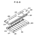
- Figure 6 is a schematic perspective view showing a recording head according to a third embodiment of the present invention.
- the present embodiment is substantially similar in construction to the above-described second embodiment, and differs from the latter in that as described above, one slit corresponds to a plurality of electro-thermal converting members and droplets forming a plurality of dots are discharged from one slit.
- the reference numeral 220 designates a glass substrate, on which is provided a heat generating resistance layer, on which are disposed patterned Al electrode 241, whereby electro-thermal converting members 217 are constituted.
- a protective layer formed of SiO2 is provided on the electro-thermal converting members 217 and electrodes 241 to thereby constitute a heater board.
- Fluid resistance elements 219 are disposed on the opposite sides of each electro-thermal converting member 217, whereby pressure waves can be prevented from being propagated in the lengthwise direction of the slit, i.e., the direction of arrangement of the electro-thermal converting members.
- each electro-thermal converting member 217 to prevent the interference between the pressure waves and to exhaust created minute bubbles, they are rightly positioned by the construction of the present invention to thereby display the effect thereof at its maximum.
- the reference numeral 221 denotes a spacer which keeps the spacing between the slit plate 212 and the substrate 220 constant and defines a liquid path.
- the recording head 211 is fixed to the head supporting means (not shown) of the apparatus with the aid of positioning apertures 214, whereby positioning of the head is accomplished.
- the positioning apertures of the recording head are formed with good accuracy simultaneously with the through-holes which provide the orifices and therefore, accurate positioning of the recording head using the orifice plate is simplified.
- the positioning apertures in the orifice plate can be easily formed without the addition of any special high-degree process, an ink jet recording head having highly accurate and inexpensive positioning apertures can be obtained with ease.
- This specification discloses an orifice plate provided with openings capable of defining discharge ports for discharging the ink of a recording head carried on an ink jet recording apparatus, characterized by the provision of positioning portions usable for the positioning of the discharge ports in the ink jet recording apparatus.
- the specification also discloses an ink jet recording head using such orifice plate, and an ink jet recording apparatus carrying the head thereon.
Landscapes
- Engineering & Computer Science (AREA)
- Manufacturing & Machinery (AREA)
- Particle Formation And Scattering Control In Inkjet Printers (AREA)
Applications Claiming Priority (4)
| Application Number | Priority Date | Filing Date | Title |
|---|---|---|---|
| JP151083/88 | 1988-06-21 | ||
| JP15108388 | 1988-06-21 | ||
| JP1155581A JP2831380B2 (ja) | 1988-06-21 | 1989-06-20 | オリフィスプレート及びインクジェット記録ヘッドの製造方法,ならびに該オリフィスプレートを用いたインクジェット記録装置 |
| JP155581/89 | 1989-06-20 |
Publications (3)
| Publication Number | Publication Date |
|---|---|
| EP0352468A2 true EP0352468A2 (fr) | 1990-01-31 |
| EP0352468A3 EP0352468A3 (en) | 1990-09-05 |
| EP0352468B1 EP0352468B1 (fr) | 1994-12-07 |
Family
ID=26480454
Family Applications (1)
| Application Number | Title | Priority Date | Filing Date |
|---|---|---|---|
| EP19890111168 Expired - Lifetime EP0352468B1 (fr) | 1988-06-21 | 1989-06-20 | Procédé de fabrication d'une plaque à tuyères pour une tête d'imprimante à jet d'encre |
Country Status (3)
| Country | Link |
|---|---|
| EP (1) | EP0352468B1 (fr) |
| DE (1) | DE68919768T2 (fr) |
| ES (1) | ES2064383T3 (fr) |
Cited By (8)
| Publication number | Priority date | Publication date | Assignee | Title |
|---|---|---|---|---|
| EP0564295A1 (fr) * | 1992-04-02 | 1993-10-06 | Hewlett-Packard Company | Tête d'impression et son procédé de fabrication |
| EP0770487A1 (fr) * | 1995-10-25 | 1997-05-02 | Hewlett-Packard Company | Orifice de tête d'impression non-circulaire |
| EP0792744A3 (fr) * | 1996-02-29 | 1998-11-18 | Hewlett-Packard Company | Orifice de tête d'impression asymétrique |
| KR19990077695A (ko) * | 1998-03-10 | 1999-10-25 | 디. 크레이그 노룬드 | 잉크젯 프린팅 장치용 프린트헤드, 다공성판과 그 형성 방법 및 프린트헤드 구성 방법 |
| EP1138496A3 (fr) * | 2000-03-31 | 2002-01-30 | Canon Kabushiki Kaisha | Tête d'éjection de liquide, appareil d'éjection de liquide et procédé de production d'une tête d'éjection de liquide |
| US6527370B1 (en) | 1999-09-09 | 2003-03-04 | Hewlett-Packard Company | Counter-boring techniques for improved ink-jet printheads |
| EP1176019A3 (fr) * | 2000-07-25 | 2003-07-30 | Sony Corporation | Imprimante et tête d'impression à grande largeur |
| US6938988B2 (en) | 2003-02-10 | 2005-09-06 | Hewlett-Packard Development Company, L.P. | Counter-bore of a fluid ejection device |
Family Cites Families (1)
| Publication number | Priority date | Publication date | Assignee | Title |
|---|---|---|---|---|
| US4047186A (en) * | 1976-01-26 | 1977-09-06 | International Business Machines Corporation | Pre-aimed nozzle for ink jet recorder and method of manufacture |
-
1989
- 1989-06-20 EP EP19890111168 patent/EP0352468B1/fr not_active Expired - Lifetime
- 1989-06-20 ES ES89111168T patent/ES2064383T3/es not_active Expired - Lifetime
- 1989-06-20 DE DE1989619768 patent/DE68919768T2/de not_active Expired - Fee Related
Cited By (16)
| Publication number | Priority date | Publication date | Assignee | Title |
|---|---|---|---|---|
| US5453769A (en) * | 1992-04-02 | 1995-09-26 | Schantz; Christopher A. | Printhead and a method for the manufacture thereof |
| EP0564295A1 (fr) * | 1992-04-02 | 1993-10-06 | Hewlett-Packard Company | Tête d'impression et son procédé de fabrication |
| US6527369B1 (en) | 1995-10-25 | 2003-03-04 | Hewlett-Packard Company | Asymmetric printhead orifice |
| EP0770487A1 (fr) * | 1995-10-25 | 1997-05-02 | Hewlett-Packard Company | Orifice de tête d'impression non-circulaire |
| US6557974B1 (en) | 1995-10-25 | 2003-05-06 | Hewlett-Packard Company | Non-circular printhead orifice |
| EP0792744A3 (fr) * | 1996-02-29 | 1998-11-18 | Hewlett-Packard Company | Orifice de tête d'impression asymétrique |
| KR19990077695A (ko) * | 1998-03-10 | 1999-10-25 | 디. 크레이그 노룬드 | 잉크젯 프린팅 장치용 프린트헤드, 다공성판과 그 형성 방법 및 프린트헤드 구성 방법 |
| US6527370B1 (en) | 1999-09-09 | 2003-03-04 | Hewlett-Packard Company | Counter-boring techniques for improved ink-jet printheads |
| EP1138496A3 (fr) * | 2000-03-31 | 2002-01-30 | Canon Kabushiki Kaisha | Tête d'éjection de liquide, appareil d'éjection de liquide et procédé de production d'une tête d'éjection de liquide |
| US6652062B2 (en) | 2000-03-31 | 2003-11-25 | Canon Kabushiki Kaisha | Liquid discharge recording head with orifice plate having extended portion fixed to recording head main body, liquid discharge recording apparatus having such head, and method for manufacturing such head |
| US6975466B2 (en) | 2000-03-31 | 2005-12-13 | Canon Kabushiki Kaisha | Liquid discharge recording head, liquid discharge recording apparatus, and method for manufacturing liquid discharge head |
| EP1176019A3 (fr) * | 2000-07-25 | 2003-07-30 | Sony Corporation | Imprimante et tête d'impression à grande largeur |
| US6793319B2 (en) | 2000-07-25 | 2004-09-21 | Sony Corporation | Printer and printer head |
| EP1688256A1 (fr) * | 2000-07-25 | 2006-08-09 | Sony Corporation | Imprimante et tête d'impression à grande largeur |
| US7240986B2 (en) | 2000-07-25 | 2007-07-10 | Sony Corporation | Printer and printer head |
| US6938988B2 (en) | 2003-02-10 | 2005-09-06 | Hewlett-Packard Development Company, L.P. | Counter-bore of a fluid ejection device |
Also Published As
| Publication number | Publication date |
|---|---|
| DE68919768T2 (de) | 1995-05-04 |
| DE68919768D1 (de) | 1995-01-19 |
| EP0352468B1 (fr) | 1994-12-07 |
| ES2064383T3 (es) | 1995-02-01 |
| EP0352468A3 (en) | 1990-09-05 |
Similar Documents
| Publication | Publication Date | Title |
|---|---|---|
| EP0627314B1 (fr) | Tête d'impression à jet d'encre améliorée pour imprimante matricielle à points | |
| US4367480A (en) | Head device for ink jet printer | |
| CA1169292A (fr) | Plateau a buses pour tete d'impression au jet d'encre | |
| JP3152259B2 (ja) | ルーフシュータ型熱インクジェット印字ヘッド | |
| US5160577A (en) | Method of fabricating an aperture plate for a roof-shooter type printhead | |
| JP4006441B2 (ja) | インクジェットプリンタ用プリントヘッド | |
| JP3327246B2 (ja) | インクジェット記録ヘッド及びその製造方法 | |
| US5659343A (en) | Method of forming an ink jet recording head having an orifice plate with positioning openings for precisely locating discharge ports in a recording apparatus | |
| EP1179430B1 (fr) | Tête d'impression et son procédé de fabrication | |
| EP1452316A1 (fr) | Tete d'impression a jet d'encre, imprimante a jet d'encre la contenant et procede de fabrication de cette tete | |
| EP0624471A2 (fr) | Motif de masque pour la réalisation de buses à jet d'encre coniques | |
| US4980703A (en) | Print head for ink-jet printing apparatus | |
| JP2006192622A (ja) | 液体吐出ヘッド、液体吐出装置、及び液体吐出ヘッドの製造方法 | |
| EP0352468B1 (fr) | Procédé de fabrication d'une plaque à tuyères pour une tête d'imprimante à jet d'encre | |
| US5948290A (en) | Method of fabricating an ink jet recording head | |
| JP2001162811A (ja) | インクジェット式記録ヘッドユニット及びその製造方法 | |
| KR20020032980A (ko) | 프린트 어레이 헤드 및 그 제조방법 | |
| CN1328050C (zh) | 液体喷射头以及液体喷射装置 | |
| EP1211077B1 (fr) | Procédé de formation d'un orifice dans un élément d'une tête d'impression, élément à orifices, tête d'impression à jet d'encre munie d'un tel élément et imprimante à jet d'encre munie d'une telle tête | |
| JP3739532B2 (ja) | インクジェット式記録装置 | |
| US6692103B2 (en) | Ink jet recording head | |
| JP3126276B2 (ja) | インクジェット記録ヘッド | |
| JPH10296982A (ja) | インクジェットヘッド用ノズル板の製造方法及びインクジェットヘッド | |
| JP2002001966A (ja) | 記録ヘッドと記録ヘッドの製造方法及びインクジェット記録装置 | |
| US7207652B2 (en) | Balanced satellite distributions |
Legal Events
| Date | Code | Title | Description |
|---|---|---|---|
| PUAI | Public reference made under article 153(3) epc to a published international application that has entered the european phase |
Free format text: ORIGINAL CODE: 0009012 |
|
| AK | Designated contracting states |
Kind code of ref document: A2 Designated state(s): DE ES FR GB IT |
|
| PUAL | Search report despatched |
Free format text: ORIGINAL CODE: 0009013 |
|
| AK | Designated contracting states |
Kind code of ref document: A3 Designated state(s): DE ES FR GB IT |
|
| 17P | Request for examination filed |
Effective date: 19901221 |
|
| 17Q | First examination report despatched |
Effective date: 19920722 |
|
| GRAA | (expected) grant |
Free format text: ORIGINAL CODE: 0009210 |
|
| AK | Designated contracting states |
Kind code of ref document: B1 Designated state(s): DE ES FR GB IT |
|
| REF | Corresponds to: |
Ref document number: 68919768 Country of ref document: DE Date of ref document: 19950119 |
|
| REG | Reference to a national code |
Ref country code: ES Ref legal event code: FG2A Ref document number: 2064383 Country of ref document: ES Kind code of ref document: T3 |
|
| ITF | It: translation for a ep patent filed | ||
| ET | Fr: translation filed | ||
| PLBE | No opposition filed within time limit |
Free format text: ORIGINAL CODE: 0009261 |
|
| STAA | Information on the status of an ep patent application or granted ep patent |
Free format text: STATUS: NO OPPOSITION FILED WITHIN TIME LIMIT |
|
| 26N | No opposition filed | ||
| REG | Reference to a national code |
Ref country code: GB Ref legal event code: IF02 |
|
| PGFP | Annual fee paid to national office [announced via postgrant information from national office to epo] |
Ref country code: DE Payment date: 20070614 Year of fee payment: 19 |
|
| PGFP | Annual fee paid to national office [announced via postgrant information from national office to epo] |
Ref country code: ES Payment date: 20070626 Year of fee payment: 19 |
|
| PGFP | Annual fee paid to national office [announced via postgrant information from national office to epo] |
Ref country code: GB Payment date: 20070620 Year of fee payment: 19 |
|
| PGFP | Annual fee paid to national office [announced via postgrant information from national office to epo] |
Ref country code: IT Payment date: 20070626 Year of fee payment: 19 |
|
| PGFP | Annual fee paid to national office [announced via postgrant information from national office to epo] |
Ref country code: FR Payment date: 20070608 Year of fee payment: 19 |
|
| GBPC | Gb: european patent ceased through non-payment of renewal fee |
Effective date: 20080620 |
|
| REG | Reference to a national code |
Ref country code: FR Ref legal event code: ST Effective date: 20090228 |
|
| PG25 | Lapsed in a contracting state [announced via postgrant information from national office to epo] |
Ref country code: DE Free format text: LAPSE BECAUSE OF NON-PAYMENT OF DUE FEES Effective date: 20090101 |
|
| PG25 | Lapsed in a contracting state [announced via postgrant information from national office to epo] |
Ref country code: GB Free format text: LAPSE BECAUSE OF NON-PAYMENT OF DUE FEES Effective date: 20080620 |
|
| REG | Reference to a national code |
Ref country code: ES Ref legal event code: FD2A Effective date: 20080621 |
|
| PG25 | Lapsed in a contracting state [announced via postgrant information from national office to epo] |
Ref country code: IT Free format text: LAPSE BECAUSE OF NON-PAYMENT OF DUE FEES Effective date: 20080620 Ref country code: FR Free format text: LAPSE BECAUSE OF NON-PAYMENT OF DUE FEES Effective date: 20080630 |
|
| PG25 | Lapsed in a contracting state [announced via postgrant information from national office to epo] |
Ref country code: ES Free format text: LAPSE BECAUSE OF NON-PAYMENT OF DUE FEES Effective date: 20080621 |