EP0352608B1 - Fabrication de matériaux pour garniture d'étanchéité en PTFE renforcé - Google Patents
Fabrication de matériaux pour garniture d'étanchéité en PTFE renforcé Download PDFInfo
- Publication number
- EP0352608B1 EP0352608B1 EP89113186A EP89113186A EP0352608B1 EP 0352608 B1 EP0352608 B1 EP 0352608B1 EP 89113186 A EP89113186 A EP 89113186A EP 89113186 A EP89113186 A EP 89113186A EP 0352608 B1 EP0352608 B1 EP 0352608B1
- Authority
- EP
- European Patent Office
- Prior art keywords
- composite
- ptfe
- filler
- pressure
- polytetrafluoroethylene
- Prior art date
- Legal status (The legal status is an assumption and is not a legal conclusion. Google has not performed a legal analysis and makes no representation as to the accuracy of the status listed.)
- Expired - Lifetime
Links
Images


Classifications
-
- B—PERFORMING OPERATIONS; TRANSPORTING
- B32—LAYERED PRODUCTS
- B32B—LAYERED PRODUCTS, i.e. PRODUCTS BUILT-UP OF STRATA OF FLAT OR NON-FLAT, e.g. CELLULAR OR HONEYCOMB, FORM
- B32B15/00—Layered products comprising a layer of metal
- B32B15/04—Layered products comprising a layer of metal comprising metal as the main or only constituent of a layer, which is next to another layer of the same or of a different material
- B32B15/08—Layered products comprising a layer of metal comprising metal as the main or only constituent of a layer, which is next to another layer of the same or of a different material of synthetic resin
- B32B15/085—Layered products comprising a layer of metal comprising metal as the main or only constituent of a layer, which is next to another layer of the same or of a different material of synthetic resin comprising polyolefins
-
- B—PERFORMING OPERATIONS; TRANSPORTING
- B29—WORKING OF PLASTICS; WORKING OF SUBSTANCES IN A PLASTIC STATE IN GENERAL
- B29C—SHAPING OR JOINING OF PLASTICS; SHAPING OF MATERIAL IN A PLASTIC STATE, NOT OTHERWISE PROVIDED FOR; AFTER-TREATMENT OF THE SHAPED PRODUCTS, e.g. REPAIRING
- B29C43/00—Compression moulding, i.e. applying external pressure to flow the moulding material; Apparatus therefor
- B29C43/02—Compression moulding, i.e. applying external pressure to flow the moulding material; Apparatus therefor of articles of definite length, i.e. discrete articles
- B29C43/027—Compression moulding, i.e. applying external pressure to flow the moulding material; Apparatus therefor of articles of definite length, i.e. discrete articles having an axis of symmetry
-
- B—PERFORMING OPERATIONS; TRANSPORTING
- B29—WORKING OF PLASTICS; WORKING OF SUBSTANCES IN A PLASTIC STATE IN GENERAL
- B29C—SHAPING OR JOINING OF PLASTICS; SHAPING OF MATERIAL IN A PLASTIC STATE, NOT OTHERWISE PROVIDED FOR; AFTER-TREATMENT OF THE SHAPED PRODUCTS, e.g. REPAIRING
- B29C43/00—Compression moulding, i.e. applying external pressure to flow the moulding material; Apparatus therefor
- B29C43/02—Compression moulding, i.e. applying external pressure to flow the moulding material; Apparatus therefor of articles of definite length, i.e. discrete articles
- B29C43/18—Compression moulding, i.e. applying external pressure to flow the moulding material; Apparatus therefor of articles of definite length, i.e. discrete articles incorporating preformed parts or layers, e.g. compression moulding around inserts or for coating articles
-
- B—PERFORMING OPERATIONS; TRANSPORTING
- B29—WORKING OF PLASTICS; WORKING OF SUBSTANCES IN A PLASTIC STATE IN GENERAL
- B29C—SHAPING OR JOINING OF PLASTICS; SHAPING OF MATERIAL IN A PLASTIC STATE, NOT OTHERWISE PROVIDED FOR; AFTER-TREATMENT OF THE SHAPED PRODUCTS, e.g. REPAIRING
- B29C70/00—Shaping composites, i.e. plastics material comprising reinforcements, fillers or preformed parts, e.g. inserts
- B29C70/04—Shaping composites, i.e. plastics material comprising reinforcements, fillers or preformed parts, e.g. inserts comprising reinforcements only, e.g. self-reinforcing plastics
- B29C70/26—Non-fibrous reinforcements only
-
- B—PERFORMING OPERATIONS; TRANSPORTING
- B30—PRESSES
- B30B—PRESSES IN GENERAL
- B30B15/00—Details of, or accessories for, presses; Auxiliary measures in connection with pressing
- B30B15/06—Platens or press rams
- B30B15/062—Press plates
- B30B15/064—Press plates with heating or cooling means
-
- B—PERFORMING OPERATIONS; TRANSPORTING
- B32—LAYERED PRODUCTS
- B32B—LAYERED PRODUCTS, i.e. PRODUCTS BUILT-UP OF STRATA OF FLAT OR NON-FLAT, e.g. CELLULAR OR HONEYCOMB, FORM
- B32B15/00—Layered products comprising a layer of metal
- B32B15/04—Layered products comprising a layer of metal comprising metal as the main or only constituent of a layer, which is next to another layer of the same or of a different material
- B32B15/08—Layered products comprising a layer of metal comprising metal as the main or only constituent of a layer, which is next to another layer of the same or of a different material of synthetic resin
-
- B—PERFORMING OPERATIONS; TRANSPORTING
- B32—LAYERED PRODUCTS
- B32B—LAYERED PRODUCTS, i.e. PRODUCTS BUILT-UP OF STRATA OF FLAT OR NON-FLAT, e.g. CELLULAR OR HONEYCOMB, FORM
- B32B15/00—Layered products comprising a layer of metal
- B32B15/18—Layered products comprising a layer of metal comprising iron or steel
-
- B—PERFORMING OPERATIONS; TRANSPORTING
- B32—LAYERED PRODUCTS
- B32B—LAYERED PRODUCTS, i.e. PRODUCTS BUILT-UP OF STRATA OF FLAT OR NON-FLAT, e.g. CELLULAR OR HONEYCOMB, FORM
- B32B15/00—Layered products comprising a layer of metal
- B32B15/20—Layered products comprising a layer of metal comprising aluminium or copper
-
- B—PERFORMING OPERATIONS; TRANSPORTING
- B32—LAYERED PRODUCTS
- B32B—LAYERED PRODUCTS, i.e. PRODUCTS BUILT-UP OF STRATA OF FLAT OR NON-FLAT, e.g. CELLULAR OR HONEYCOMB, FORM
- B32B27/00—Layered products comprising a layer of synthetic resin
- B32B27/18—Layered products comprising a layer of synthetic resin characterised by the use of special additives
- B32B27/20—Layered products comprising a layer of synthetic resin characterised by the use of special additives using fillers, pigments, thixotroping agents
-
- B—PERFORMING OPERATIONS; TRANSPORTING
- B32—LAYERED PRODUCTS
- B32B—LAYERED PRODUCTS, i.e. PRODUCTS BUILT-UP OF STRATA OF FLAT OR NON-FLAT, e.g. CELLULAR OR HONEYCOMB, FORM
- B32B27/00—Layered products comprising a layer of synthetic resin
- B32B27/32—Layered products comprising a layer of synthetic resin comprising polyolefins
- B32B27/322—Layered products comprising a layer of synthetic resin comprising polyolefins comprising halogenated polyolefins, e.g. PTFE
-
- B—PERFORMING OPERATIONS; TRANSPORTING
- B32—LAYERED PRODUCTS
- B32B—LAYERED PRODUCTS, i.e. PRODUCTS BUILT-UP OF STRATA OF FLAT OR NON-FLAT, e.g. CELLULAR OR HONEYCOMB, FORM
- B32B3/00—Layered products comprising a layer with external or internal discontinuities or unevennesses, or a layer of non-planar shape; Layered products comprising a layer having particular features of form
- B32B3/26—Layered products comprising a layer with external or internal discontinuities or unevennesses, or a layer of non-planar shape; Layered products comprising a layer having particular features of form characterised by a particular shape of the outline of the cross-section of a continuous layer; characterised by a layer with cavities or internal voids ; characterised by an apertured layer
- B32B3/266—Layered products comprising a layer with external or internal discontinuities or unevennesses, or a layer of non-planar shape; Layered products comprising a layer having particular features of form characterised by a particular shape of the outline of the cross-section of a continuous layer; characterised by a layer with cavities or internal voids ; characterised by an apertured layer characterised by an apertured layer, the apertures going through the whole thickness of the layer, e.g. expanded metal, perforated layer, slit layer regular cells B32B3/12
-
- B—PERFORMING OPERATIONS; TRANSPORTING
- B32—LAYERED PRODUCTS
- B32B—LAYERED PRODUCTS, i.e. PRODUCTS BUILT-UP OF STRATA OF FLAT OR NON-FLAT, e.g. CELLULAR OR HONEYCOMB, FORM
- B32B37/00—Methods or apparatus for laminating, e.g. by curing or by ultrasonic bonding
- B32B37/06—Methods or apparatus for laminating, e.g. by curing or by ultrasonic bonding characterised by the heating method
-
- B—PERFORMING OPERATIONS; TRANSPORTING
- B32—LAYERED PRODUCTS
- B32B—LAYERED PRODUCTS, i.e. PRODUCTS BUILT-UP OF STRATA OF FLAT OR NON-FLAT, e.g. CELLULAR OR HONEYCOMB, FORM
- B32B37/00—Methods or apparatus for laminating, e.g. by curing or by ultrasonic bonding
- B32B37/08—Methods or apparatus for laminating, e.g. by curing or by ultrasonic bonding characterised by the cooling method
-
- F—MECHANICAL ENGINEERING; LIGHTING; HEATING; WEAPONS; BLASTING
- F16—ENGINEERING ELEMENTS AND UNITS; GENERAL MEASURES FOR PRODUCING AND MAINTAINING EFFECTIVE FUNCTIONING OF MACHINES OR INSTALLATIONS; THERMAL INSULATION IN GENERAL
- F16J—PISTONS; CYLINDERS; SEALINGS
- F16J15/00—Sealings
- F16J15/02—Sealings between relatively-stationary surfaces
- F16J15/06—Sealings between relatively-stationary surfaces with solid packing compressed between sealing surfaces
- F16J15/10—Sealings between relatively-stationary surfaces with solid packing compressed between sealing surfaces with non-metallic packing
- F16J15/12—Sealings between relatively-stationary surfaces with solid packing compressed between sealing surfaces with non-metallic packing with metal reinforcement or covering
- F16J15/121—Sealings between relatively-stationary surfaces with solid packing compressed between sealing surfaces with non-metallic packing with metal reinforcement or covering with metal reinforcement
- F16J15/122—Sealings between relatively-stationary surfaces with solid packing compressed between sealing surfaces with non-metallic packing with metal reinforcement or covering with metal reinforcement generally parallel to the surfaces
-
- F—MECHANICAL ENGINEERING; LIGHTING; HEATING; WEAPONS; BLASTING
- F16—ENGINEERING ELEMENTS AND UNITS; GENERAL MEASURES FOR PRODUCING AND MAINTAINING EFFECTIVE FUNCTIONING OF MACHINES OR INSTALLATIONS; THERMAL INSULATION IN GENERAL
- F16L—PIPES; JOINTS OR FITTINGS FOR PIPES; SUPPORTS FOR PIPES, CABLES OR PROTECTIVE TUBING; MEANS FOR THERMAL INSULATION IN GENERAL
- F16L23/00—Flanged joints
- F16L23/16—Flanged joints characterised by the sealing means
- F16L23/18—Flanged joints characterised by the sealing means the sealing means being rings
-
- B—PERFORMING OPERATIONS; TRANSPORTING
- B29—WORKING OF PLASTICS; WORKING OF SUBSTANCES IN A PLASTIC STATE IN GENERAL
- B29K—INDEXING SCHEME ASSOCIATED WITH SUBCLASSES B29B, B29C OR B29D, RELATING TO MOULDING MATERIALS OR TO MATERIALS FOR MOULDS, REINFORCEMENTS, FILLERS OR PREFORMED PARTS, e.g. INSERTS
- B29K2027/00—Use of polyvinylhalogenides or derivatives thereof as moulding material
- B29K2027/12—Use of polyvinylhalogenides or derivatives thereof as moulding material containing fluorine
- B29K2027/18—PTFE, i.e. polytetrafluoroethylene, e.g. ePTFE, i.e. expanded polytetrafluoroethylene
-
- B—PERFORMING OPERATIONS; TRANSPORTING
- B29—WORKING OF PLASTICS; WORKING OF SUBSTANCES IN A PLASTIC STATE IN GENERAL
- B29K—INDEXING SCHEME ASSOCIATED WITH SUBCLASSES B29B, B29C OR B29D, RELATING TO MOULDING MATERIALS OR TO MATERIALS FOR MOULDS, REINFORCEMENTS, FILLERS OR PREFORMED PARTS, e.g. INSERTS
- B29K2105/00—Condition, form or state of moulded material or of the material to be shaped
- B29K2105/06—Condition, form or state of moulded material or of the material to be shaped containing reinforcements, fillers or inserts
- B29K2105/16—Fillers
-
- B—PERFORMING OPERATIONS; TRANSPORTING
- B29—WORKING OF PLASTICS; WORKING OF SUBSTANCES IN A PLASTIC STATE IN GENERAL
- B29L—INDEXING SCHEME ASSOCIATED WITH SUBCLASS B29C, RELATING TO PARTICULAR ARTICLES
- B29L2031/00—Other particular articles
- B29L2031/26—Sealing devices, e.g. packaging for pistons or pipe joints
-
- B—PERFORMING OPERATIONS; TRANSPORTING
- B32—LAYERED PRODUCTS
- B32B—LAYERED PRODUCTS, i.e. PRODUCTS BUILT-UP OF STRATA OF FLAT OR NON-FLAT, e.g. CELLULAR OR HONEYCOMB, FORM
- B32B2307/00—Properties of the layers or laminate
- B32B2307/70—Other properties
- B32B2307/732—Dimensional properties
- B32B2307/734—Dimensional stability
-
- B—PERFORMING OPERATIONS; TRANSPORTING
- B32—LAYERED PRODUCTS
- B32B—LAYERED PRODUCTS, i.e. PRODUCTS BUILT-UP OF STRATA OF FLAT OR NON-FLAT, e.g. CELLULAR OR HONEYCOMB, FORM
- B32B2309/00—Parameters for the laminating or treatment process; Apparatus details
- B32B2309/02—Temperature
-
- B—PERFORMING OPERATIONS; TRANSPORTING
- B32—LAYERED PRODUCTS
- B32B—LAYERED PRODUCTS, i.e. PRODUCTS BUILT-UP OF STRATA OF FLAT OR NON-FLAT, e.g. CELLULAR OR HONEYCOMB, FORM
- B32B2311/00—Metals, their alloys or their compounds
- B32B2311/24—Aluminium
-
- B—PERFORMING OPERATIONS; TRANSPORTING
- B32—LAYERED PRODUCTS
- B32B—LAYERED PRODUCTS, i.e. PRODUCTS BUILT-UP OF STRATA OF FLAT OR NON-FLAT, e.g. CELLULAR OR HONEYCOMB, FORM
- B32B2311/00—Metals, their alloys or their compounds
- B32B2311/30—Iron, e.g. steel
-
- B—PERFORMING OPERATIONS; TRANSPORTING
- B32—LAYERED PRODUCTS
- B32B—LAYERED PRODUCTS, i.e. PRODUCTS BUILT-UP OF STRATA OF FLAT OR NON-FLAT, e.g. CELLULAR OR HONEYCOMB, FORM
- B32B2327/00—Polyvinylhalogenides
- B32B2327/12—Polyvinylhalogenides containing fluorine
- B32B2327/18—PTFE, i.e. polytetrafluoroethylene
-
- B—PERFORMING OPERATIONS; TRANSPORTING
- B32—LAYERED PRODUCTS
- B32B—LAYERED PRODUCTS, i.e. PRODUCTS BUILT-UP OF STRATA OF FLAT OR NON-FLAT, e.g. CELLULAR OR HONEYCOMB, FORM
- B32B2581/00—Seals; Sealing equipment; Gaskets
-
- Y—GENERAL TAGGING OF NEW TECHNOLOGICAL DEVELOPMENTS; GENERAL TAGGING OF CROSS-SECTIONAL TECHNOLOGIES SPANNING OVER SEVERAL SECTIONS OF THE IPC; TECHNICAL SUBJECTS COVERED BY FORMER USPC CROSS-REFERENCE ART COLLECTIONS [XRACs] AND DIGESTS
- Y10—TECHNICAL SUBJECTS COVERED BY FORMER USPC
- Y10T—TECHNICAL SUBJECTS COVERED BY FORMER US CLASSIFICATION
- Y10T156/00—Adhesive bonding and miscellaneous chemical manufacture
- Y10T156/10—Methods of surface bonding and/or assembly therefor
- Y10T156/1052—Methods of surface bonding and/or assembly therefor with cutting, punching, tearing or severing
- Y10T156/1056—Perforating lamina
-
- Y—GENERAL TAGGING OF NEW TECHNOLOGICAL DEVELOPMENTS; GENERAL TAGGING OF CROSS-SECTIONAL TECHNOLOGIES SPANNING OVER SEVERAL SECTIONS OF THE IPC; TECHNICAL SUBJECTS COVERED BY FORMER USPC CROSS-REFERENCE ART COLLECTIONS [XRACs] AND DIGESTS
- Y10—TECHNICAL SUBJECTS COVERED BY FORMER USPC
- Y10T—TECHNICAL SUBJECTS COVERED BY FORMER US CLASSIFICATION
- Y10T156/00—Adhesive bonding and miscellaneous chemical manufacture
- Y10T156/10—Methods of surface bonding and/or assembly therefor
- Y10T156/1052—Methods of surface bonding and/or assembly therefor with cutting, punching, tearing or severing
- Y10T156/1062—Prior to assembly
- Y10T156/1075—Prior to assembly of plural laminae from single stock and assembling to each other or to additional lamina
-
- Y—GENERAL TAGGING OF NEW TECHNOLOGICAL DEVELOPMENTS; GENERAL TAGGING OF CROSS-SECTIONAL TECHNOLOGIES SPANNING OVER SEVERAL SECTIONS OF THE IPC; TECHNICAL SUBJECTS COVERED BY FORMER USPC CROSS-REFERENCE ART COLLECTIONS [XRACs] AND DIGESTS
- Y10—TECHNICAL SUBJECTS COVERED BY FORMER USPC
- Y10T—TECHNICAL SUBJECTS COVERED BY FORMER US CLASSIFICATION
- Y10T428/00—Stock material or miscellaneous articles
- Y10T428/23—Sheet including cover or casing
- Y10T428/239—Complete cover or casing
-
- Y—GENERAL TAGGING OF NEW TECHNOLOGICAL DEVELOPMENTS; GENERAL TAGGING OF CROSS-SECTIONAL TECHNOLOGIES SPANNING OVER SEVERAL SECTIONS OF THE IPC; TECHNICAL SUBJECTS COVERED BY FORMER USPC CROSS-REFERENCE ART COLLECTIONS [XRACs] AND DIGESTS
- Y10—TECHNICAL SUBJECTS COVERED BY FORMER USPC
- Y10T—TECHNICAL SUBJECTS COVERED BY FORMER US CLASSIFICATION
- Y10T428/00—Stock material or miscellaneous articles
- Y10T428/24—Structurally defined web or sheet [e.g., overall dimension, etc.]
- Y10T428/24273—Structurally defined web or sheet [e.g., overall dimension, etc.] including aperture
- Y10T428/24322—Composite web or sheet
- Y10T428/24331—Composite web or sheet including nonapertured component
- Y10T428/24339—Keyed
- Y10T428/24347—From both sides
Definitions
- the present invention relates generally to reinforced gasketing materials and specifically to a filled polytetrafluoroethylene stainless steel reinforced gasketing material and a process whereby such a material can be produced.
- PTFE has also been bonded to metal by an adhesive material to form a composite useful as a gasketing material with improved dimensional stability.
- U.S. Patent No. 4,103,913 discloses a multilayer engine head gasket which resists scoring, scratching and fretting corrosion and maintains the desired shape.
- This laminated gasket material consists of a metal core sandwiched between intermediate layers of phosphate and outer layers formed from polytetrafluorethylene which may be mixed with molybdenum disulfide.
- the phosphate layer is stated to enhance the ability of the PTFE to adhere to the steel, and there is no suggestion that the gasket material described in this patent could be formed without the adhesive phosphate layer.
- U.S. Patent No. 2,976,093 discloses a method of making a reinforced PTFE laminate wherein PTFE powder is placed in a mold, a perforated metal reinforcing member is placed on the powder, and additional PTFE powder is layered on the metal member. These materials are compacted under pressure to produce a preformed composite, which is then subjected to sintering temperatures.
- the reinforced PTFE laminate thus produced is characterized by variations in density, surface dimples and inadequate adhesion between the PTFE and the metal. Consequently, gaskets produced according to this process are susceptible to fluid leakage and internal cold flow following the application of an external load. Moreover, creep relaxation and gasket deformation at high temperatures and internal pressures may present substantial problems in gaskets produced according to the aforementioned process that will make them unsuitable for use in these types of environments.
- the prior art therefore, has failed to disclose a PTFE gasket which is characterized by low creep relaxation, minimum cold flow, excellent resistance against deformation and excellent fluid sealability under high external loads at high temperatures and pressures and in the presence of corrosive chemicals.
- the prior art has further failed to disclose a method of making a laminated filled PTFE-metal reinforced gasketing material having the foregoing characteristics wherein the PTFE is actually bonded to the metal without binders or adhesives.
- a primary object of the present invention to overcome the disadvantages of the prior art and to provide a filled PTFE reinforced gasketing material characterized by resistance to creep relaxation, cold flow and deformation to produce a superior seal under high temperatures and external loads in adverse environments and to provide a process for making such a gasketing material.
- the composite gasketing material of the present invention is characterized by high strength, excellent recovery and superior creep relaxation resistance wherein at least one metal reinforcing member is encapsulated by and has bonded thereto outer layers of a PTFE/filler material.
- the present invention provides an improved gasket material and a process for preparing such a gasket material.
- Gasketing products produced as described herein demonstrate superior physical and functional properties in applications where conventional gasketing materials have failed. Evaluations of the gasket material produced according to the process described herein demonstrate that this material displays superior creep relaxation resistance, improved recovery, excellent sealing capacity and substantially increased material strength when compared to previous PTFE gasketing materials.
- the present process actually bonds the filled PTFE to the reinforcing metal. The strong filled PTFE-metal bonds resulting from this process are obtained without etching or prior treatment of the metal and without binders or adhesives.
- Composite gasketing materials can be readily made in the form of sheets from which the individual gaskets can be cut or, alternatively, in the form of individual gaskets in suitable molds.
- the versatility of the present process permits the production of high performance gaskets of special sizes and configurations with the same ease as gaskets of standard sizes and shapes.
- the gasketing material produced according to the process of the present invention is a multilayer laminated composite that takes a variety of forms. This material may be structured as shown in the drawings or may have a different arrangement, depending on the end use or application of the gasket formed from the composite.
- the materials preferred for use in the present process are filled polytetrafluoroethylene (PTFE), stainless steel and aluminum foil. Filled PTFE is preferred for use in the present process since the processing conditions described below do not produce the same superior results when unfilled or pure PTFE is used. Both barium sulfate and silica (e.g., Opal Supersil Silica) have been demonstrated to function effectively as fillers in this process.
- glass microballoons may be used as a filler material for gasket applications in which high compressibility is required.
- the filled PTFE may be in the form of either sintered or unsintered sheets.
- Sintered PTFE/filler sheets that can be successfully employed in the present process to produce superior gasketing materials are available from Garlock Inc under the designations Style 3500, which is a sintered PTFE/silica sheet, and Style 3510, which is a sintered PTFE/barytes sheet.
- Style 3500 which is a sintered PTFE/silica sheet
- Style 3510 which is a sintered PTFE/barytes sheet.
- Other commercially available sintered or unsintered PTFE/filler sheets may also be used advantageously to form the gasketing material of the present invention.
- Figure 1 illustrates a well-known process for the preparation of an unsintered PTFE/filler sheet for use in forming the superior gasketing material of the present invention.
- PTFE/silica, PTFE/barytes, or other PTFE/filler blends may be used in this process.
- the PTFE/filler blend selected is mixed with Stoddard solvent (petroleum naphtha) in a high speed mixer and then filtered and pressed to remove most of the solvent.
- Stoddard solvent (petroleum naphtha) in a high speed mixer and then filtered and pressed to remove most of the solvent.
- a PTFE/filler cake 10 is obtained.
- the cake 10 is passed back and forth through a nip 16 formed between calendar rolls 12 and 14.
- a sheet 18 of PTFE/filler having a thickness T1 is formed.
- the final gap G of the nip 16 controls the final thickness T1 of the sheet 10.
- the sheet 18 is cut into segments 20 having the dimensions X and Y as shown in Figure 1.
- the cut sheet segments 20 are dried, either in a batch type or conveyor type oven, which removes most of the remaining solvent.
- the time required to dry the sheet segments 20 depends on their thickness T1. Drying time in a batch oven at 394°K (250°F) varies from 2.5 hours for a 0,08 cm (1/32 inch) sheet to 5 hours for a sheet 0,32 cm (1/8 inches) thick. Any residual solvent contained in the sheet 20 will be eliminated by further processing.
- Figure 2 illustrates one possible composition of a multilayer composite gasketing material 22.
- the thickness of the finished composite sheet can vary, but preferably should be about 0,32 cm (1/8 inch) for most applications.
- the X and Y dimensions are ideally 60,96 cm x 60,96 cm (24 inches x 24 inches) or 81,28 cm x 81,28 cm (32 inches x 32 inches), although other sizes could be used as well.
- the thickness T1 of each ply of PTFE/filler material will depend in large measure upon the desired thickness of the final composite.
- the gap G of nip 16 can be adjusted accordingly to produce PTFE/filler sheets of the desired thickness.
- the composite of Figure 2 includes three PTFE/filler sheets, although, as mentioned above, other numbers of these sheets sould be employed.
- Reinforcement of the gasketing materials of the present invention is achieved by providing one or more sheets of metal, preferably stainless steel, which contact the PTFE/filler sheet and impart dimensional stability and other desirable properties to the composite.
- a major advantage of using stainless steel sheets is that they do not chemically or mechanically alter the surface characteristics of the PTFE/filler material. It has been discovered that perforated stainless steel produces results superior to those obtained with nonperforated stainless steel.
- a stainless steel sheet material particularly preferred for use in the present gasket product and process is known as 316 SS, which is 0,020 cm (0.008 inches) thick and has a staggered pattern of perforations. The perforations are 0,16 cm (1/16 inches) in diameter, with 0,24 cm (3/32 inches) between their centers.
- Each 6,45 cm2 (square inch) of perforated sheet optimally has about 41% open area.
- Stainless steel sheets having these characteristics are readily available commercially in sheets of 60,96 cm x 60,96 cm (24 inches x 24 inches) or 81,28 cm x 81,28 cm (32 inches x 32 inches).
- the size of the stainless steel sheets should be selected to be slightly larger than that of the PTFE/filler sheets for reasons that will be discussed in greater detail below.
- the stainless steel reinforcement sheets should be in degreased form to be ready for use in forming the present gasketing materials.
- Figure 2 shows two perforated stainless steel sheets 24 inserted between adjacent pairs of the PTFE/filler sheets 20.
- the gasketing material composite 22 of Figure 2 further includes outer layers 26, which are aluminum foil.
- the primary function of the aluminum foil is to protect the surface of the gasketing material during handling as well as during the pressure stages of the present process described below. At the end of the process, the foil is stripped from the gasket composite.
- One available aluminum foil suitable for use in this process is 2,54 ⁇ 10 ⁇ 3cm (0.001 inches) thick, is temper hard and is available in 60,96 cm (24 inch) and 81,28 cm (32 inch) wide rolls.
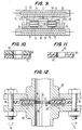
- the multilayer composite 22 of Figure 2 is subjected to a pressure sintering step, which is shown diagramatically in Figure 3.
- a pressure sintering step which is shown diagramatically in Figure 3.
- the entire assembly is then transferred to a sintering press 28.
- the sintering press includes an upper platen 30 and a lower platen 32.
- the upper platen 30 includes an electric heating element 34
- the lower platen 32 includes a similar heating element 36.
- the heating elements 34 and 36 must extend over the entire width of the composite 22 to insure proper sintering of the outermost edges 38 of the composite.
- the heating elements 34 and 36 are heated to 672° K (750°F), which is sufficiently above the gel point of both sintered and unsintered PTFE/filler sheets to achieve a strong filled PTFE-metal bond.
- 672° K 750°F
- the specific sintering temperature selected will depend upon the gel point for the PTFE-filler combination used to form the gasketing material. A temperature of 672°K (750°F), however, will achieve the desired results for almost all applications.
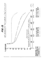
- the actual pressure sintering cycle to which the composite 22 is subjected is divided into five intervals or stages. The last three of these intervals are depicted graphically in Figure 4.
- interval A-B (not shown in Figure 4) the composite 22 is subjected to approximately 10 to 15 seconds of preheating at a pressure P1 of about 689,74 kPa (100 psi). This both preheats the material and also eliminates any waviness that might be present in the PTFE/filler sheets 20.
- the evacuation of residual moisture and solvent from the PTFE/filler material is initiated by this first preheating step.
- Interval B-C commences after approximately 15 seconds when residual moisture and solvent vapor fumes are visible.
- the pressure P1 is then reduced to 0 kPa (0 psi) and the platens 30 and 32 are opened momentarily and then closed so that the pressure on the composite 22 is again about 689,74 kPa (100 psi).
- This rapid pressure change is referred to as low pressure bumping and is repeated 3 to 5 times to accelerate the evacuation of the residual solvent and moisture in the composite 22.
- the PTFE/filler sheets 20 and stainless steel reinforcing sheets 24 are still the separate and distinguishable entities shown in Figure 3.
- approximately 90% of the residual solvent has been evacuated.
- Interval C-D is the first stage in the process shown in Figure 4. Up to this point the composite 22 has been in the pressure sintering assembly a total of about 20 to 30 seconds. At the beginning of this interval the pressure P1 on the platens 30 and 32 is immediately increased to about 4138,45 kPa (600 psi). As the PTFE/filler material slowly reaches the gel state, a drop in pressure is recorded from the beginning point C to the end point D of this interval. During the C-D interval the PTFE/filler material is being densified and forced through and around the perforations in reinforcing sheets 24, while evacuation of residual vapor fumes continues.
- the metal reinforcement sheets 24 are required to be larger than the PTFE/filler sheets 18. If the metal sheets 24 do not extend beyond the edges 38 of the composite 22 as shown in Figure 3, the metal sheets 24 will become completely enclosed by the PTFE/filler material. The result will be the entrapment of residual fumes, leading ultimately to blistering and delamination of the layers of the composite 22.
- interval D-E in Figure 4 it will be noted that point D is a critical point.
- the PTFE/filler material is close to the melting point and, as it actually changes from a solid state to a gel state at point D, this material expands. Expansion of the PTFE/filler material causes the pressure P1 to increase above the 4138,45 kPa (600 psi) pressure shown at point C and then to level off at point E.
- FIG. 4 illustrates three different PTFE/filler-metal reinforcement arrangements.
- Curve 40 is representative of pressure changes and expansion when barytes (barium sulfate) is used as the PTFE filler and the composite contains one stainless steel reinforcing sheet or insert.
- Curves 42 and 44 both represent the behavior of PTFE and a silica filler. However, the composite of curve 42 includes only one stainless steel reinforcing sheet, while the composite of curve 44, like composite 22, includes two stainless steel reinforcement sheets.
- the D-E interval is a very critical stage in the pressure sintering process because additional strike through and extrusion of the PTFE/filler material occurs in and around the perforations of the stainless steel sheet. Mechanical bonding between the filled PTFE and the steel sheet takes place during this stage. Moreover, the PTFE/filler sheets are chemically fused together during this stage to produce the homogeneous structure 46 which substantially totally encapsulates the stainless steel sheets 24 as shown in Figures 5 and 6.
- the composite 22 has experienced a total dwell time in the sintering press (Interval A-E) of about 1.5 to 2.0 minutes at 672°K (750°F), which allows the PTFE/filler material to fully reach the gel state and fuse together. This is shown in Figure 4 by the leveling off the pressure curves, which indicates a constant pressure P1. Once the PTFE/filler material reaches the gel state, it is considered to be fully sintered. The resulting composite can, therefore, be transferred and cooled at an point in the E-F interval.
- the total time required for sintering will depend upon the thickness of the composite 22. For example, a 0,16 cm (1/16 inch) thick composite of two plies of PTFE/silica and one ply of perforated stainless steel will require about 60 seconds to sinter. A composite of the same materials that is 0,32 cm (1/8 inch) thick requires about 83 seconds to sinter. Prolonged sintering at 672°K (750°F) is inadvisable. Such sintering does not improve the results obtained but, rather, results in degradation or gradual loss of the PTFE to toxic products.
- the next step in the present process is a rapid cooling step under pressure, which is shown diagramatically in Figure 5.
- the sintered composite is transferred from the sintering press of Figure 3 to the cooling apparatus of Figure 5.
- the sintered composite 46 is placed between fluid-cooled platens 48 and 50. Cooling fluid or coolant is circulated through inlets 52 and outlets 54 in the direction shown by arrows 53.
- Pressure P2 represented by the arrows in Figure 5, is applied to the platens 48 and 50.
- the pressure P2 is equal to the pressure P1, which is 4138,45 kPa (600 psi). This pressure is maintained for about 3 to 4 minutes.
- This rapid pressure cooling step is required to keep the composite 46 flat as it cools and to maintain a strong and uniform bond between the PTFE/filler material and the metal reinforcing sheets.
- the composite does not exhibit planar shrinkage because the steel reinforcing sheets 24 prevent shrinkage.
- a slight reduction in the thickness of the composite 46 will occur as the material cools under the pressure load P2.
- the composite 46 is shown in cross-section in Figure 5 and in a fragmentary view in Figure 6.
- the three PTFE/filler sheets 20 have fused together and totally encapsulated the steel sheets 24.
- fusing and bonding of the PTFE/filler material was accomplished during Interval C-D of the pressure sintering stage of the process.
- the final product shown in Figure 6 should optimally have a thickness T f of 0,318 cm ⁇ 0,025 cm (0.125 inch ⁇ 0.010 inch).
- the versatility of the process of the present invention permits the manufacture of both standard ring gaskets and gaskets of special configurations with equal facility from the PTFE/filler metal composition 46 of Figures 5 and 6. As will be discussed in detail below, these gaskets are particularly well suited for applications where blow-out protection as well as chemical resistance is required. Blow-out protection of the composite is provided by including multiple layers of 0,020 cm (0.008 inches) thick perforated metal.
- the pressure sintering steps should be conducted in a mold, such as the two part mold 68 shown in Figure 9, which is placed in a sintering press like the sintering press of Figure 3 for the sintering operation.
- the mold 68 is first placed in the press between the platens 30 and 32. Heating elements 34 and 36 supply the heat required to preheat the mold 68 to 672°K (750°F)
- the mold is removed from the press, the gasket assembly 60 of Figure 8 is placed in the cavity 70 of the mold 68, and the mold is returned to the press.
- the stainless steel ring 64 is centered by the outside diameter of cavity 70.
- the pressure P3 shown by the parallel arrows in Figure 9 is equal to the pressure P1.
- venting of the sintering operation is essential because of the potentially toxic residual fumes which must be evacuated. Consequently, mold cavity 70 must be properly vented, and a number of vents 72 are provided for this purpose.
- the gasket 60 is cooled as discussed in connection with Figure 5.
- the gasket is removed from the mold 68 and then pressed between two fluid cooled platens, such as platens 48 and 50 in Figure 5.
- the cooling pressure on the gasket, P2 is equal to 4138,45 kPa (600 psi) and this pressure is maintained for about 3-4 minutes. Table I provides additional information regarding cooling pressures and times for gasketing materials of different thickness.
- Figures 10 and 11 show an enlarged cross-sectional view of the gasket 60 before ( Figure 10) and after ( Figure 11) pressure sintering.
- the layers or plies of PTFE/filler material 62 and the perforated metal ring 64 are separate.
- the PTFE/filler material 62 and the metal 64 are chemically fused and bonded together as shown in Figure 11.
- the inside diameter of metal ring 64 is completely encapsulated by the PTFE/filler material.
- the process of the present invention permits the production of many types and sizes of gaskets.
- the final thickness T f can be varied by using a PTFE/filler sheet for the PTFE/filler plies of the laminate that has a greater or lesser thickness.
- different numbers of metal reinforcing sheets could be used as well, although the metal sheets are used primarily for strength and dimensional stability.
- Figures 7-11 show the production of a precut ringtype gasket in a mold.
- a gasket having the same shape could also be cut from the composite sheet 46 of Figure 6. If the precut metal reinforcement 64 of Figure 8 is smaller than the precut PTFE rings 62, the metal ring should be completely encapsulated by the PTFE/filler material, whereas a ring cut from composite 46 ( Figure 6) will have at least some exposed metal on the edges.
- gaskets produced according to the present invention are ideal is pipes that have glass-lined flanges. These pipes typically carry extremely corrosive materials which will readily break down even stainless steel. However, because the gasketing material produced as described herein completely encapsulates the metal with PTFE/filler material, the stainless steel is not exposed and therefore is not contacted by the corrosive. If gaskets produced according to the aforementioned process are intended for use in glass-lined pipes, the filler material most suitable for such applications is one that will insure maximum compressibility of the gasketing material. Glass lined flanges ideally require a gasket with compressibility that exceeds 25%.
- Glass microballoons such as Extendospheres XOL-200, are used as the filler material in the PTFE/filler blend in place of silica, barytes or another filler to form the sheet 18, which is then processed as described in connection with Figures 7-11 to produce a gasket having a compressibility of 25-30%. This is in distinct contrast to the compressibility of available gaskets for glass-lined pipe applications which ranges from 5-10%. Gaskets made from a PTFE/glass microballoon blend-metal composite have all of the superior properties of the gaskets of Figure 11 plus high compressibility.
- the composite gasketing materials produced according to the present invention have been tested and evaluated, primarily in accordance with the rules and procedures of the American Society for Testing and Materials (ASTM) for gasketing materials.
- ASTM American Society for Testing and Materials
- a blow-out test which tests the resistance of gaskets to blow-out at varying temperatures and pressures
- a hot compression test with measures the compression set of gasketing materials subjected to heat and constant gasket load over a short time period, were conducted.
- Three different thicknesses of gasketing materials, 0,08 cm (1/32 inch), 0,16 cm (1/16 inch) and 0,32 cm (1/8 inch) were tested.
- the 0,08 cm (1/32 inch) and 0,16 cm (1/16 inch) gaskets evaluated were made of three kinds of material: a conventional pure PTFE gasketing material, a filled PTFE gasketing material (Garlock Style 3500), and a composite like that of Figure 11 including one perforated stainless steel insert or ply and two outer plies of a PTFE/silica blend.
- the 0,32 cm (1/8 inch) gasketing materials tested did not include pure PTFE of this thickness, but evaluated instead a composite like that of Figure 6 which includes two perforated stainless steel inserts or plies and three PTFE/silica plies.
- FIG. 12 illustrates an apparatus similar to that which may be used to conduct this test.
- the device of Figure 12 is essentially a two flange pipe joint.
- one of the flanges 80 or 82 must be capped or sealed in a suitable manner to allow the buildup of pressure on the gasket 61.
- the flanges 80 and 82 are the standard ANSI-2500 pounds series, which are designed for high internal pressures. Nitrogen gas is used for the test fluid, and the internal pressure can be varied from atmospheric to 34487,05 kPa (5000 psi).
- the gasket 61 is held between the flanges 80 and 82 by an external load P0, which is applied by adjusting the torque (TQ) of eight 2,54 cm (one inch) diameter alloy steel bolts 86, only two of which are shown in Figure 12.
- the torque applied for this test is varied according to thickness of the gasketing material as set forth below. Thickness of Gasket Torque (TQ) 0,08 cm (1/32 Inch) 43,4 Nm (32 ft lbs) 0,16 cm (1/16 Inch) 61,0 Nm (45 ft lbs) 0,32 cm (1/8 Inch) 84,0 Nm (62 ft lbs)
- Tables II, III and IV compare several important physical and functional properties of two types of gasketing materials produced according to the present invention, one having a single stainless steel reinforcing sheet ( Figures 7-11) and the other having two stainless steel reinforcing sheets ( Figures 2-6), conventional PTFE gasketing material and a silica filled PTFE gasketing material.
- the silica filled PTFE is made by a process that includes free sintering at 617°K to 644°K (650°F to 700°F) and has the same PTFE/silica ratio by weight as the PTFE/silica ratio in the gasketing material produced according to the present invention.
- the present process densifies the PTFE/silica material and mechanically bonds it to the metal layer and, therefore, directly produces the excellent sealability characteristic of the present gasketing materials.
- the leakage paths for PTFE gasketing materials are primarily between the flange surfaces 88 and 92 and the gasket surfaces 90 and 94. If the fluid and internal pressure P1 remains constant, the amount of leakage is directly related to the external gasket load P0. Gaskets subjected to high external loads generally have low leakage rates as shown by the sealability test results for gasket loads of 3450 kPa (500 psi) and 6900 kPa (1000 psi) in Tables II-IV. These results also indicate that there is no leakage between the metal sheet 65 and the PTFE/silica material of the gasket 61.
- Elongation, tensile strength and blow-out resistance are material strength properties that are controlled by the metal reinforcement in the gasketing material of the present invention.
- the gasketing composites evaluated in Tables II-IV and Figures 13-15 contain metal reinforcement layers which are 0,020 cm (0.008 inch) thick, have 0,16 cm (1/16 inch) round perforations, and have 41% open area per 6,45 cm2 (square inch).
- the tensile strength and blow-out resistance can be improved by using a thicker metal reinforcing sheet or by using a metal sheet with smaller perforations and a smaller percentage of open area.
- a 0,32 cm (1/8 inch) thick gasket composite with one metal reinforcement sheet 0,020 cm (0.008 inch) thick having 0,051 cm (0.02 inch) diameter perforations and 22% open area per 6,45 cm2 (square inch) was tested at 589°K (600°F) and did not exhibit gasket blowout at 575°K (575°F) or at 589°K (600°F).
- Filled PFTE gasketing materials however, have an upper temperature limit of 533°K (500°F).
- the compression of ring gaskets formed from the three thicknesses of gasketing materials tested above was also evaluated through a hot compression test of the gasketing materials when they are subjected to heat and constant gasket load over a short time period of one-half hour.
- This test is conducted by placing the gasket to be tested between two electrically heated and polished platens. A constant hydraulic load of 24668 kPa (3575 psi) is applied on the gasket and maintained throughout the one-half hour test. At the start of the test the temperature is room temperature and is gradually increased to as high as 589°K (600°F). As the platens are heated, the polished platen surfaces do not restrict the radial flow of the gasket so that the thickness of the gasket is reduced.
- the conventional PTFE gasketing materials had spread radially to produce an irregularly shaped ring with a greatly reduced central opening to resemble a doughnut, the PTFE/silica blend gasketing material showed a lesser degree of radial spread with some irregularity in shape, while the 0,08 cm (1/32 inch) and 0,16 cm (1/16 inch) PTFE/filler-metal composite with one metal ply had spread radially only a small amount.
- the 0,32 cm (1/8 inch) PTFE/filler-metal composite had spread radially so that the central opening was reduced somewhat in size, but the gaskets still were regular in shape.
- the gasket formed from the PTFE/silica blend with one perforated stainless steel reinforcing sheet exhibited a significantly lower per cent compression than did the gaskets formed from either pure PTFE or from prior PTFE/Silica gasketing materials.
- the 0,32 cm (1/8 inch) thick gasket formed from PTFE/silica blend with two perforated stainless steel reinforcing sheets or inserts showed even a lesser percentage of compression.
- the processing conditions of the present invention cause the PTFE/filler material to actually bond to the stainless steel reinforcing sheets.
- pure PTFE does not bond to stainless steel.
- Tables V and VI below set forth the results of bonding experiments conducted on metal reinforced PTFE/filler gasketing material composites using silica (Table V) and barytes (Table VI) as the filler.
- the silica filler demonstrated somewhat better bonding than did the barytes. It is likely that other fillers or combinations of fillers will achieve a similar result, and consequently, the use of fillers which function like silica and barytes is contemplated to be within the scope of the present invention.
- a application for which gaskets formed according to the present process are especially well-suited is in the blow tank lines of a batch digester in a pulp and paper mill.
- the temperature cycles ranging from ambient to 444°K (340°F) and considerable hammering or shock loading with high internal pressures are the predominate factors contributing to the failure of available filled PTFE gasketing materials.
- a gasket like that shown in Figure 7 with one metal reinforcing sheet was tested under the conditions associated with a batch digester.
- Both PTFE/silica- and PTFE/barytes-reinforced gaskets having a single perforated stainless steel sheet were tested. These gaskets were cut from a 0,32 cm (1/8 inch) thick sheet of gasketing material produced according to the present invention.
- the gaskets were placed in pipe joints similar to that shown in Figure 14. As the system is cooled and subsequently heated the pipe and the two flange joints expand and contract, which results in high and low cycles of external load (P0 in Figure 12) on the gasket. Gaskets produced as described herein performed successfully under these conditions because of their excellent recovery and creep relaxation resistance properties. Additionally, the high tensile strength and low elongation of the present gaskets did not blow-out or extrude even with the high internal pressure in the digester lines.
- the filled PTFE metal reinforced gasketing material of the present invention will be successfully employed to form gaskets for a wide variety of applications where standard filled PTFE gasketing materials have failed to provide a strong, reliable seal. It is contemplated that the process of the present invention can be used to produce gasketing materials for applications where high strength, excellent recovery and superior creep relaxation resistance properties are required.
Landscapes
- Engineering & Computer Science (AREA)
- Mechanical Engineering (AREA)
- General Engineering & Computer Science (AREA)
- Chemical & Material Sciences (AREA)
- Composite Materials (AREA)
- Laminated Bodies (AREA)
- Gasket Seals (AREA)
- Sealing Material Composition (AREA)
- Processing And Handling Of Plastics And Other Materials For Molding In General (AREA)
Claims (12)
- Procédé de production d'un matériau stable pour garnitures d'étanchéité comprenant les étapes suivantes :(a) former une première plaque en un mélange de polytétrafluoroéthylène et au moins une charge ;(b) préparer une seconde plaque en métal perforé ;(c) préparer une troisième plaque en feuille d'aluminium ;(d) former un composite dans lequel ladite seconde plaque de métal est étalée en alternance avec lesdites premières plaques de polytétrafluoroéthylène/charge afin que les couches les plus extérieures soient lesdites premières plaques de polytétrafluoro-éthylène/charge ;(e) appliquer une couche de ladite troisième plaque en forme de feuille pour recouvrir chaque couche la plus extérieure de ladite première plaque dudit composite ;(f) soumettre le composite formé à l'étape (e) à un frittage sous pression à une température dépassant le point de gélification dudit matériau de polytétrafluoroéthylène ;(g) ledit frittage sous pression dudit composite comprenant les étapes suivantes :(I) préchauffer ledit composite pendant 10 à 15 secondes sous environ 689,74 kPa (100 livres par pouce carré) ;(II) réduire rapidement la pression appliquée audit composite d'environ 689,74 kPa (100 livres par pouce carré) à 0 kPa (0 livre par pouce carré) ;(III) répéter rapidement le cycle de pression des étapes (I) et (II) de 3 à 5 fois ;(IV) augmenter rapidement la pression exercée sur ledit composite jusqu'à environ 4 138,45 kPa (600 livres par pouce carré) et(V) maintenir ledit composite sous une pression d'environ 4 138,45 kPa (600 livres par pouce carré) pendant un temps suffisant pour transformer complètement ledit polytétrafluoroéthylène/charge en un gel et faire extruder ledit gel à travers les perforations de ladite plaque métallique, pour lier ladite plaque métallique et enrober complètement ladite plaque métallique, et(h) soumettre le composite fritté sous pression formé aux étapes (f) et (g) à un refroidissement rapide sous pression.
- Procédé selon la revendication 1, dans lequel ladite première plaque est choisie dans le groupe consistant en polytétrafluoroéthylène et la silice, polytétrafluoroéthylène et sulfate de baryum, et polytétrafluoroéthylène et microbilles de verre.
- Procédé selon la revendication 2, dans lequel ledit métal est de l'acier inoxydable.
- Procédé selon la revendication 3, dans lequel l'une desdites secondes plaques métalliques est insérée entre deux desdites plaques de polytétrafluoroéthylène/charge pour former lesdits composés.
- Procédé selon la revendication 4, dans lequel la température de l'étape (f) est d'au moins 672 °K (750 °F).
- Procédé selon l'une des revendications 1 à 5, dans lequel ladite étape de refroidissement rapide consiste à soumettre le composite fritté sous pression à une pression d'environ 4 138,45 kPa (600 livres par pouce carré) appliquée au moyen d'une presse refroidie par un fluide pendant un temps suffisant pour refroidir ledit composite.
- Procédé selon l'une des revendications 3 à 5, dans lequel deux desdites secondes plaques métalliques sont insérées entre d'autres couches desdites premières plaques de polytétrafluoroéthylène/charge pour former lesdits composites.
- Procédé selon la revendication 1 caractérisé par la formation d'un composite à plusieurs couches comprenant une couche centrale en acier inoxydable perforé, deux couches intermédiaires d'une plaque constituée d'un mélange de polytétrafluoroéthylène et d'une charge et deux couches extérieures en feuille d'aluminium, dans lequel chacune desdites couches intermédiaires est placée entre ladite couche centrale et ladite couche extérieure.
- Procédé selon la revendication 8, dans lequel lesdites couches intermédiaires sont constituées d'un mélange choisi dans le groupe consistant en polytétrafluoroéthylène et silice, polytétrafluoroéthylène et barytes, et polytétrafluoroéthylène et microbilles de verre.
- Procédé selon la revendication 8, dans lequel ledit refroidissement rapide consiste à appliquer une pression d'environ 4 138,45 kPa (600 livres par pouce carré) audit composite au moyen d'une presse refroidie par un fluide, et en particulier d'une presse refroidie par eau.
- Procédé selon la revendication 1, caractérisé par la formation d'un composite en couches comprenant une paire de couches-extérieures en feuille d'aluminium et une pluralité de couches intérieures alternées en acier inoxydable perforé et en matériau polytétrafluoroéthylène/charge, lesdites couches intérieures étant disposées de manière qu'une couche de polytétrafluoroéthylène/charge soit adjacente à chaque couche extérieure et à chaque couche en acier inoxydable.
- Matériau pour garniture d'étanchéité formé suivant un procédé décrit dans les revendications 1, 8 ou 11.
Applications Claiming Priority (2)
| Application Number | Priority Date | Filing Date | Title |
|---|---|---|---|
| US224393 | 1988-07-26 | ||
| US07/224,393 US4913951A (en) | 1988-07-26 | 1988-07-26 | Fabrication of reinforced PTFE gasketing material |
Publications (3)
| Publication Number | Publication Date |
|---|---|
| EP0352608A2 EP0352608A2 (fr) | 1990-01-31 |
| EP0352608A3 EP0352608A3 (en) | 1990-11-28 |
| EP0352608B1 true EP0352608B1 (fr) | 1995-01-25 |
Family
ID=22840480
Family Applications (1)
| Application Number | Title | Priority Date | Filing Date |
|---|---|---|---|
| EP89113186A Expired - Lifetime EP0352608B1 (fr) | 1988-07-26 | 1989-07-19 | Fabrication de matériaux pour garniture d'étanchéité en PTFE renforcé |
Country Status (6)
| Country | Link |
|---|---|
| US (1) | US4913951A (fr) |
| EP (1) | EP0352608B1 (fr) |
| AT (1) | ATE117625T1 (fr) |
| DE (1) | DE68920789T2 (fr) |
| ES (1) | ES2068853T3 (fr) |
| GR (1) | GR3014961T3 (fr) |
Cited By (1)
| Publication number | Priority date | Publication date | Assignee | Title |
|---|---|---|---|---|
| US7666947B2 (en) | 2004-04-07 | 2010-02-23 | Garlock Sealing Technologies, Llc | Gasket material |
Families Citing this family (44)
| Publication number | Priority date | Publication date | Assignee | Title |
|---|---|---|---|---|
| US5056757A (en) * | 1990-10-12 | 1991-10-15 | Fisher Controls International, Inc. | Packing containment for live loaded fugitive emission seals |
| US5213749A (en) * | 1991-07-31 | 1993-05-25 | Westinghouse Air Brake Company | Method of forming a rubber seal having a metallic insert |
| US5172920A (en) * | 1992-01-28 | 1992-12-22 | Diamond Manufacturing Co. | Composite material for gaskets |
| US5240766A (en) * | 1992-04-01 | 1993-08-31 | Hollingsworth & Vose Company | Gasket material |
| US5299811A (en) * | 1992-12-23 | 1994-04-05 | Siemens Automotive Limited | Seal member mounted in housing pocket by resilient retaining member |
| US5520772A (en) * | 1993-09-02 | 1996-05-28 | Technologies Development, Inc. | Laminating machine with two-stage heating |
| US5651554A (en) * | 1995-06-07 | 1997-07-29 | Townsend; Newton A. | Non-abrading gasket assembly |
| JP3336864B2 (ja) * | 1996-01-18 | 2002-10-21 | 松下電工株式会社 | 積層体の製造方法およびその製造装置 |
| US5882817A (en) * | 1997-03-03 | 1999-03-16 | Space Systems/Loral, Inc. | Battery cell design for a bipolar rechargeable battery |
| WO1998058199A1 (fr) * | 1997-06-16 | 1998-12-23 | Garlock Inc. | Element d'etancheite fendu |
| DE19804283B4 (de) * | 1998-02-04 | 2006-10-12 | Sgl Carbon Ag | Metallverstärkter Graphitschichtstoff |
| US6139026A (en) * | 1999-03-25 | 2000-10-31 | Pfaudler, Inc. | Stabilized "O" ring gasket seal |
| US6485809B1 (en) * | 1999-08-11 | 2002-11-26 | W. L. Gore & Associates Gmbh | Low stress to seal gasket |
| DE19953240A1 (de) | 1999-11-04 | 2001-05-10 | Basf Ag | Verbundelemente |
| JP2002243041A (ja) * | 2001-02-19 | 2002-08-28 | Japan Gore Tex Inc | テープ状シール材及びその製造方法 |
| US20030175520A1 (en) * | 2002-03-13 | 2003-09-18 | Grutta James T. | Formed composite structural members and methods and apparatus for making the same |
| DE10242731B4 (de) * | 2002-09-13 | 2004-09-16 | Federal-Mogul Friedberg Gmbh | Gleitringdichtung |
| US20040211062A1 (en) * | 2003-04-28 | 2004-10-28 | Brian Lang | Method for producing a gasket |
| US7867345B2 (en) * | 2003-10-06 | 2011-01-11 | Ntn Corporation | Manufacturing method of thin component, bearing ring, thrust needle roller bearing, manufacturing method of rolling bearing ring, rolling bearing ring, and rolling bearing |
| US20050244245A1 (en) * | 2004-04-30 | 2005-11-03 | Anatoly Efremov | Method and devices to limit a creep of mechanical fasteners |
| US20060201613A1 (en) * | 2005-03-10 | 2006-09-14 | Norihisa Minowa | Bonding perfluoroelastomers to aluminum |
| US7455301B2 (en) * | 2006-03-02 | 2008-11-25 | Virginia Sealing Products, Inc. | Seamless corrugated insert gasket and method of forming the same |
| EP2005041B1 (fr) * | 2006-03-28 | 2012-07-11 | Interface Solutions, Inc. | Joint forme de diverses matieres |
| WO2008058153A2 (fr) * | 2006-11-06 | 2008-05-15 | Garlock Sealing Technologies Llc | Joint moulé à faible contrainte, et son procédé de réalisation |
| EP2109639A4 (fr) * | 2007-02-06 | 2010-08-25 | Garlock Sealing Technologies | Ptfe rempli de nitrure de bore |
| ITTO20070519A1 (it) * | 2007-07-12 | 2009-01-14 | Seval Srl | Guarnizioni metalliche lamellari e procedimento di produzione |
| US8579299B2 (en) * | 2009-04-03 | 2013-11-12 | Interface Solutions, Inc. | Gasket having adhesive element |
| US8931481B2 (en) | 2009-06-04 | 2015-01-13 | Redmed Limited | Flow generator chassis assembly with suspension seal |
| US20110287677A1 (en) * | 2010-05-19 | 2011-11-24 | Garlock Sealing Technologies, Llc | Flexible reinforced gasket |
| US9234589B2 (en) | 2010-10-20 | 2016-01-12 | Garlock Sealing Technologies, Llc | Extreme temperature gasket and method of making the same |
| US20130082447A1 (en) | 2011-10-04 | 2013-04-04 | Garlock Sealing Technologies, Llc | Spiral wound gasket |
| KR20130067538A (ko) * | 2011-12-14 | 2013-06-25 | 현대자동차주식회사 | 복합재료 샤시프레임 및 그 제작 방법 |
| FR3008339B1 (fr) * | 2013-07-15 | 2015-08-07 | Commissariat Energie Atomique | Procede de mise en forme d'une plaque en un polytetrafluoroethylene fritte et restructure et ses applications |
| JP6779236B2 (ja) | 2015-05-15 | 2020-11-04 | コーニンクラケ ダウ エグバート ビー.ブイ. | カプセル、そのようなカプセルから飲用可能な飲料を調製するためのシステム、およびそのようなカプセルの飲料調製装置における使用方法 |
| KR102633888B1 (ko) | 2015-05-15 | 2024-02-06 | 코닌클리케 도우베 에그베르츠 비.브이. | 캡슐, 이러한 캡슐로부터 마실 수 있는 음료를 제조하기 위한 시스템 및 음료 제조 장치 내의 이러한 캡슐의 이용 |
| US9701058B2 (en) * | 2015-09-17 | 2017-07-11 | Teadit N.A., Inc. | Spiral-wound PTFE gasket and methods of manufacture |
| KR101932842B1 (ko) * | 2016-04-01 | 2018-12-26 | 주식회사 엘지화학 | 봉지 필름 |
| NL2016779B1 (en) * | 2016-05-13 | 2017-11-16 | Douwe Egberts Bv | A capsule and a system for preparing a potable beverage from such a capsule |
| WO2017221105A1 (fr) * | 2016-06-23 | 2017-12-28 | Manoj Harilal Akkad | Procédé pour améliorer la résistance au délaminage d'une couche de revêtement appliquée sur un substrat monolithique rigide |
| NL2019254B9 (en) | 2016-10-07 | 2018-09-10 | Douwe Egberts Bv | A capsule, a system for preparing a potable beverage from such a capsule and use of such a capsule in a beverage preparation device |
| NL2019253B1 (en) | 2017-07-14 | 2019-01-28 | Douwe Egberts Bv | Assembly of a capsule and a brew chamber, brew chamber, beverage preparation machine, capsule and use of a capsule. |
| CN109648768B (zh) * | 2018-11-21 | 2024-05-31 | 江苏宣臻防腐工程有限公司 | 一种钢衬四氟笼箍等钢复合工艺 |
| CN109501424B (zh) * | 2018-12-26 | 2023-09-12 | 江苏金由新材料有限公司 | 一种ptfe复合密封垫片及其制备工艺 |
| CN114571751B (zh) * | 2022-03-07 | 2023-06-06 | 常州华日新材有限公司 | Smc片材浸渍挤压装置 |
Family Cites Families (12)
| Publication number | Priority date | Publication date | Assignee | Title |
|---|---|---|---|---|
| US2054210A (en) * | 1933-05-22 | 1936-09-15 | Crown Cork & Seal Co | Clutch plate |
| GB721949A (en) * | 1951-07-24 | 1955-01-19 | Glacier Co Ltd | Improvements in or relating to leaf spring assemblies |
| GB867782A (en) * | 1957-03-30 | 1961-05-10 | Boulton & Paul Ltd | Improvements in or relating to laminated material |
| US2976093A (en) * | 1958-03-28 | 1961-03-21 | Durion Company Inc | Fabrication of plastic material |
| FR1303584A (fr) * | 1961-08-02 | 1962-09-14 | Procédé de revêtement d'une surface métallique par une couche de polytétrafluoroéthylène chargé, et matériaux composites ainsi obtenus pour la réalisation de surfaces de frottement, telles que celles de coussinets | |
| US3304221A (en) * | 1963-04-18 | 1967-02-14 | Dixon Corp | Polytetrafluoroethylene laminates and method of making the same |
| US3421972A (en) * | 1965-06-28 | 1969-01-14 | Koppers Co Inc | Process for directly bonding polytetrafluoroethylene to metal,adhesive composition used therefor and laminated product thereof |
| US3532570A (en) * | 1966-06-08 | 1970-10-06 | Du Pont | Dimensionally stable electrical circuit laminates |
| GB1336000A (en) * | 1970-12-29 | 1973-10-31 | Uzina Tractorul Brasov | Moulding friction discs |
| US4103913A (en) * | 1976-04-19 | 1978-08-01 | Felt Products Mfg. Co. | Fretting corrosion resistant gasket and method of making same |
| FR2362315A1 (fr) * | 1976-08-18 | 1978-03-17 | Kleber Colombes | Joint d'etancheite |
| US4670089A (en) * | 1986-02-27 | 1987-06-02 | Dixon Industries Corporation | Method of bonding polytetrafluoro-ethylene composition to metal substrates |
-
1988
- 1988-07-26 US US07/224,393 patent/US4913951A/en not_active Expired - Lifetime
-
1989
- 1989-07-19 DE DE68920789T patent/DE68920789T2/de not_active Expired - Lifetime
- 1989-07-19 EP EP89113186A patent/EP0352608B1/fr not_active Expired - Lifetime
- 1989-07-19 AT AT89113186T patent/ATE117625T1/de not_active IP Right Cessation
- 1989-07-19 ES ES89113186T patent/ES2068853T3/es not_active Expired - Lifetime
-
1995
- 1995-02-03 GR GR950400210T patent/GR3014961T3/el unknown
Cited By (2)
| Publication number | Priority date | Publication date | Assignee | Title |
|---|---|---|---|---|
| US7666947B2 (en) | 2004-04-07 | 2010-02-23 | Garlock Sealing Technologies, Llc | Gasket material |
| US7851555B2 (en) | 2004-04-07 | 2010-12-14 | Garlock Sealing Technologies Llc | Gasket material |
Also Published As
| Publication number | Publication date |
|---|---|
| EP0352608A3 (en) | 1990-11-28 |
| US4913951A (en) | 1990-04-03 |
| ATE117625T1 (de) | 1995-02-15 |
| GR3014961T3 (en) | 1995-05-31 |
| DE68920789T2 (de) | 1995-05-18 |
| ES2068853T3 (es) | 1995-05-01 |
| DE68920789D1 (de) | 1995-03-09 |
| EP0352608A2 (fr) | 1990-01-31 |
Similar Documents
| Publication | Publication Date | Title |
|---|---|---|
| EP0352608B1 (fr) | Fabrication de matériaux pour garniture d'étanchéité en PTFE renforcé | |
| EP0365871B1 (fr) | Méthode de production d'un matériau pour joints et joint hautement compressible | |
| US5998339A (en) | Wet type sliding apparatus comprising radial bearing | |
| US9618122B2 (en) | Low-stress molded gasket and method of making same | |
| EP0849219B1 (fr) | Pate obturatrice a base de graphite expanse et procede de fabrication associe | |
| US5792525A (en) | Creep resistant shaped article of densified expanded polytetrafluoroethylene | |
| US4961891A (en) | Method of making high compressibility gasket material | |
| CA2016869C (fr) | Procede de soudage d'elements en polytetrafluoroethylene fritte, a charge | |
| US4820787A (en) | Shaped article of an oriented tetrafluoroethylene polymer | |
| US7851555B2 (en) | Gasket material | |
| US5670189A (en) | Compression molding two or more polytetrafluoroethylene resin layers to form a pressure pad | |
| DE3785810T2 (de) | Verwendung einer festen, fliessbaren, metall enthaltenden polymerzusammensetzung in formgebungsprozessen. | |
| JP2018529055A (ja) | 渦巻形ptfeガスケットおよびその製造方法 | |
| EP0302279B1 (fr) | Matériau pour garniture d'étanchéité et procédé pour le fabriquer par compactage de couches collées à un métal de base | |
| WO1994002547A1 (fr) | Polytetrafluoroethylene presentant une meilleure resistance au fluage et preparation de ce compose | |
| DE2346499A1 (de) | Verfahren zur herstellung von koerpern aus pulver durch isostatisches warmpressen | |
| EP2050561B1 (fr) | Procédé et appareil de fabrication | |
| CZ20011381A3 (cs) | Ploąný polotovar a způsob jeho výroby | |
| JPWO1998024612A1 (ja) | 変性ポリテトラフルオロエチレン成形品の接合成形方法 | |
| JP2992589B2 (ja) | ポリテトラフルオロエチレン樹脂フィルムおよびその製造方法 | |
| RU2030293C1 (ru) | Многослойный композиционный материал и способ его изготовления | |
| JP3862853B2 (ja) | グランドパッキンおよびその製造方法 | |
| JPH02175805A (ja) | 複合合金シリンダおよびその製造方法 | |
| JPS638262A (ja) | 炭化珪素焼結体からなる摺動部材およびその製造方法 | |
| CA1204098A (fr) | Sieges en metal fritte a charge de graphite pour clapets spheriques, et leur fabrication |
Legal Events
| Date | Code | Title | Description |
|---|---|---|---|
| PUAI | Public reference made under article 153(3) epc to a published international application that has entered the european phase |
Free format text: ORIGINAL CODE: 0009012 |
|
| AK | Designated contracting states |
Kind code of ref document: A2 Designated state(s): AT BE CH DE ES FR GB GR IT LI LU NL SE |
|
| PUAL | Search report despatched |
Free format text: ORIGINAL CODE: 0009013 |
|
| AK | Designated contracting states |
Kind code of ref document: A3 Designated state(s): AT BE CH DE ES FR GB GR IT LI LU NL SE |
|
| 17P | Request for examination filed |
Effective date: 19910124 |
|
| 17Q | First examination report despatched |
Effective date: 19931105 |
|
| GRAA | (expected) grant |
Free format text: ORIGINAL CODE: 0009210 |
|
| AK | Designated contracting states |
Kind code of ref document: B1 Designated state(s): AT BE CH DE ES FR GB GR IT LI LU NL SE |
|
| REF | Corresponds to: |
Ref document number: 117625 Country of ref document: AT Date of ref document: 19950215 Kind code of ref document: T |
|
| ET | Fr: translation filed | ||
| REF | Corresponds to: |
Ref document number: 68920789 Country of ref document: DE Date of ref document: 19950309 |
|
| ITF | It: translation for a ep patent filed | ||
| REG | Reference to a national code |
Ref country code: GR Ref legal event code: FG4A Free format text: 3014961 |
|
| REG | Reference to a national code |
Ref country code: ES Ref legal event code: FG2A Ref document number: 2068853 Country of ref document: ES Kind code of ref document: T3 |
|
| PLBE | No opposition filed within time limit |
Free format text: ORIGINAL CODE: 0009261 |
|
| STAA | Information on the status of an ep patent application or granted ep patent |
Free format text: STATUS: NO OPPOSITION FILED WITHIN TIME LIMIT |
|
| 26N | No opposition filed | ||
| REG | Reference to a national code |
Ref country code: CH Ref legal event code: NV Representative=s name: BOVARD AG PATENTANWAELTE Ref country code: CH Ref legal event code: PUE Owner name: GARLOCK INC. TRANSFER- COLTEC NORTH CAROLINA INC. |
|
| REG | Reference to a national code |
Ref country code: FR Ref legal event code: TP |
|
| BECA | Be: change of holder's address |
Free format text: 19990713 *COLTEC NORTH CAROLINA INC.:3 COLISEUM CENTRE 2550 WEST TYVOLA ROAD, CHARLOTTE NORTH CAROLINA 28217 |
|
| REG | Reference to a national code |
Ref country code: GB Ref legal event code: IF02 |
|
| PGFP | Annual fee paid to national office [announced via postgrant information from national office to epo] |
Ref country code: AT Payment date: 20020703 Year of fee payment: 14 Ref country code: NL Payment date: 20020703 Year of fee payment: 14 Ref country code: SE Payment date: 20020703 Year of fee payment: 14 |
|
| PGFP | Annual fee paid to national office [announced via postgrant information from national office to epo] |
Ref country code: CH Payment date: 20020704 Year of fee payment: 14 |
|
| PGFP | Annual fee paid to national office [announced via postgrant information from national office to epo] |
Ref country code: LU Payment date: 20020709 Year of fee payment: 14 |
|
| PGFP | Annual fee paid to national office [announced via postgrant information from national office to epo] |
Ref country code: GR Payment date: 20020723 Year of fee payment: 14 |
|
| PGFP | Annual fee paid to national office [announced via postgrant information from national office to epo] |
Ref country code: BE Payment date: 20020802 Year of fee payment: 14 |
|
| PGFP | Annual fee paid to national office [announced via postgrant information from national office to epo] |
Ref country code: ES Payment date: 20020807 Year of fee payment: 14 |
|
| PG25 | Lapsed in a contracting state [announced via postgrant information from national office to epo] |
Ref country code: LU Free format text: LAPSE BECAUSE OF NON-PAYMENT OF DUE FEES Effective date: 20030719 Ref country code: AT Free format text: LAPSE BECAUSE OF NON-PAYMENT OF DUE FEES Effective date: 20030719 |
|
| PG25 | Lapsed in a contracting state [announced via postgrant information from national office to epo] |
Ref country code: SE Free format text: LAPSE BECAUSE OF NON-PAYMENT OF DUE FEES Effective date: 20030720 |
|
| PG25 | Lapsed in a contracting state [announced via postgrant information from national office to epo] |
Ref country code: ES Free format text: LAPSE BECAUSE OF NON-PAYMENT OF DUE FEES Effective date: 20030721 |
|
| PG25 | Lapsed in a contracting state [announced via postgrant information from national office to epo] |
Ref country code: LI Free format text: LAPSE BECAUSE OF NON-PAYMENT OF DUE FEES Effective date: 20030731 Ref country code: CH Free format text: LAPSE BECAUSE OF NON-PAYMENT OF DUE FEES Effective date: 20030731 Ref country code: BE Free format text: LAPSE BECAUSE OF NON-PAYMENT OF DUE FEES Effective date: 20030731 |
|
| BERE | Be: lapsed |
Owner name: *COLTEC NORTH CAROLINA INC. Effective date: 20030731 |
|
| PG25 | Lapsed in a contracting state [announced via postgrant information from national office to epo] |
Ref country code: NL Free format text: LAPSE BECAUSE OF NON-PAYMENT OF DUE FEES Effective date: 20040201 |
|
| PG25 | Lapsed in a contracting state [announced via postgrant information from national office to epo] |
Ref country code: GR Free format text: LAPSE BECAUSE OF NON-PAYMENT OF DUE FEES Effective date: 20040205 |
|
| EUG | Se: european patent has lapsed | ||
| REG | Reference to a national code |
Ref country code: CH Ref legal event code: PL |
|
| NLV4 | Nl: lapsed or anulled due to non-payment of the annual fee |
Effective date: 20040201 |
|
| REG | Reference to a national code |
Ref country code: ES Ref legal event code: FD2A Effective date: 20030721 |
|
| PG25 | Lapsed in a contracting state [announced via postgrant information from national office to epo] |
Ref country code: IT Free format text: LAPSE BECAUSE OF NON-PAYMENT OF DUE FEES;WARNING: LAPSES OF ITALIAN PATENTS WITH EFFECTIVE DATE BEFORE 2007 MAY HAVE OCCURRED AT ANY TIME BEFORE 2007. THE CORRECT EFFECTIVE DATE MAY BE DIFFERENT FROM THE ONE RECORDED. Effective date: 20050719 |
|
| PGFP | Annual fee paid to national office [announced via postgrant information from national office to epo] |
Ref country code: DE Payment date: 20080829 Year of fee payment: 20 |
|
| PGFP | Annual fee paid to national office [announced via postgrant information from national office to epo] |
Ref country code: FR Payment date: 20080729 Year of fee payment: 20 |
|
| PGFP | Annual fee paid to national office [announced via postgrant information from national office to epo] |
Ref country code: GB Payment date: 20080729 Year of fee payment: 20 |
|
| REG | Reference to a national code |
Ref country code: GB Ref legal event code: PE20 Expiry date: 20090718 |
|
| PG25 | Lapsed in a contracting state [announced via postgrant information from national office to epo] |
Ref country code: GB Free format text: LAPSE BECAUSE OF EXPIRATION OF PROTECTION Effective date: 20090718 |