EP0352747A2 - Procédé de stabilisation d'une séparation de fréquence pour communication optique hétérodyne ou homodyne - Google Patents
Procédé de stabilisation d'une séparation de fréquence pour communication optique hétérodyne ou homodyne Download PDFInfo
- Publication number
- EP0352747A2 EP0352747A2 EP89113710A EP89113710A EP0352747A2 EP 0352747 A2 EP0352747 A2 EP 0352747A2 EP 89113710 A EP89113710 A EP 89113710A EP 89113710 A EP89113710 A EP 89113710A EP 0352747 A2 EP0352747 A2 EP 0352747A2
- Authority
- EP
- European Patent Office
- Prior art keywords
- frequency
- signal
- optical
- electrical
- output
- Prior art date
- Legal status (The legal status is an assumption and is not a legal conclusion. Google has not performed a legal analysis and makes no representation as to the accuracy of the status listed.)
- Granted
Links
- 238000000926 separation method Methods 0.000 title claims abstract description 59
- 230000003287 optical effect Effects 0.000 title claims description 232
- 238000004891 communication Methods 0.000 title claims description 23
- 230000006641 stabilisation Effects 0.000 title claims description 23
- 238000011105 stabilization Methods 0.000 title claims description 23
- 238000000034 method Methods 0.000 title claims description 19
- 239000004065 semiconductor Substances 0.000 claims abstract description 50
- 230000000087 stabilizing effect Effects 0.000 claims abstract description 14
- 230000001427 coherent effect Effects 0.000 claims abstract description 7
- 230000010287 polarization Effects 0.000 claims description 59
- 230000000737 periodic effect Effects 0.000 claims description 21
- 239000013307 optical fiber Substances 0.000 claims description 17
- 230000010355 oscillation Effects 0.000 claims description 17
- 238000001914 filtration Methods 0.000 claims 3
- 230000003111 delayed effect Effects 0.000 claims 2
- 230000000694 effects Effects 0.000 description 18
- 230000005540 biological transmission Effects 0.000 description 14
- 238000001514 detection method Methods 0.000 description 13
- 230000015556 catabolic process Effects 0.000 description 10
- 238000006731 degradation reaction Methods 0.000 description 9
- 230000003321 amplification Effects 0.000 description 6
- BJQHLKABXJIVAM-UHFFFAOYSA-N bis(2-ethylhexyl) phthalate Chemical compound CCCCC(CC)COC(=O)C1=CC=CC=C1C(=O)OCC(CC)CCCC BJQHLKABXJIVAM-UHFFFAOYSA-N 0.000 description 6
- 238000003199 nucleic acid amplification method Methods 0.000 description 6
- 238000006243 chemical reaction Methods 0.000 description 3
- 238000010276 construction Methods 0.000 description 2
- 230000003595 spectral effect Effects 0.000 description 2
- 239000013078 crystal Substances 0.000 description 1
- 230000006866 deterioration Effects 0.000 description 1
- 230000001747 exhibiting effect Effects 0.000 description 1
- 239000000835 fiber Substances 0.000 description 1
- 150000002500 ions Chemical class 0.000 description 1
- 230000001902 propagating effect Effects 0.000 description 1
Images


Classifications
-
- H—ELECTRICITY
- H04—ELECTRIC COMMUNICATION TECHNIQUE
- H04B—TRANSMISSION
- H04B10/00—Transmission systems employing electromagnetic waves other than radio-waves, e.g. infrared, visible or ultraviolet light, or employing corpuscular radiation, e.g. quantum communication
- H04B10/50—Transmitters
-
- H—ELECTRICITY
- H01—ELECTRIC ELEMENTS
- H01S—DEVICES USING THE PROCESS OF LIGHT AMPLIFICATION BY STIMULATED EMISSION OF RADIATION [LASER] TO AMPLIFY OR GENERATE LIGHT; DEVICES USING STIMULATED EMISSION OF ELECTROMAGNETIC RADIATION IN WAVE RANGES OTHER THAN OPTICAL
- H01S5/00—Semiconductor lasers
- H01S5/40—Arrangement of two or more semiconductor lasers, not provided for in groups H01S5/02 - H01S5/30
- H01S5/4025—Array arrangements, e.g. constituted by discrete laser diodes or laser bar
-
- H—ELECTRICITY
- H04—ELECTRIC COMMUNICATION TECHNIQUE
- H04B—TRANSMISSION
- H04B10/00—Transmission systems employing electromagnetic waves other than radio-waves, e.g. infrared, visible or ultraviolet light, or employing corpuscular radiation, e.g. quantum communication
- H04B10/50—Transmitters
- H04B10/572—Wavelength control
-
- H—ELECTRICITY
- H01—ELECTRIC ELEMENTS
- H01S—DEVICES USING THE PROCESS OF LIGHT AMPLIFICATION BY STIMULATED EMISSION OF RADIATION [LASER] TO AMPLIFY OR GENERATE LIGHT; DEVICES USING STIMULATED EMISSION OF ELECTROMAGNETIC RADIATION IN WAVE RANGES OTHER THAN OPTICAL
- H01S5/00—Semiconductor lasers
- H01S5/06—Arrangements for controlling the laser output parameters, e.g. by operating on the active medium
- H01S5/068—Stabilisation of laser output parameters
- H01S5/0683—Stabilisation of laser output parameters by monitoring the optical output parameters
- H01S5/0687—Stabilising the frequency of the laser
Definitions
- This invention relates generally to optical communication systems, and more particularly to systems for stabilizing wavelength or frequency separation of light sources to render them suitable for a wavelength multiplexing or frequency multiplexing systems in coherent optical communication or direct detection optical communication systems.
- a conventional wavelength or frequency separation stabilization systems for light sources is discussed in IEEE, International Conference on Communications, Conference Record 37.4.1, pp. 1219 - 1223 (1988).
- This paper is directed to fiber type Fabry-Perot resonators, or in other words, a kind of etalon, as a means for stabilizing frequency separation.
- This etalon is used as an optical frequency discriminator for converting an optical frequency to an intensity.
- the system stabilizes the optical frequency separation by detecting the change of the intensity of the output beam of the etalon that occurs when the optical frequency changes, and by using this signal as a control signal.
- frequency stability of the light sources is limited by stability of the etalon with respect to the changes in temperature, mechanical vibration, air pressure, and the like. It is therefore difficult to maintain stability for extended periods.
- a system is therefore desirable which can facilitate a frequency separation stabilization which is stable for extended periods of time.
- Wavelength division multiplexing or frequency division multiplexing optical communication systems using the above-described technique render another problem in the part of a photo-coupler output for combining the beams from a plurality of light sources is discarded without using it.
- the optical output is not, therefore, utilized effectively.
- output beams of two light sources are combined and a portion of the combined beam is subjected to optical heterodyne detection by an optical detector and converted to an electric signal.
- This electric signal and the output of an oscillator are multiplied, and a difference frequency component generated by this multiplication between the electric signal and the output of the oscillator is extracted.
- the change of this signal component is detected by a frequency discrimination circuit and this signal is applied to one or both of the semiconductor lasers so as to make the difference of the optical frequencies of the two semiconductor lasers constant.
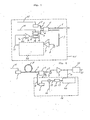
- a semiconductor laser suitably forms light sources 1 and 2.
- the output beams 3 and 4 of two semiconductor lasers 1 and 2 are combined by an optical multiplexer 5, such as a photo-coupler, and part of the beam 7 of the output is converted to an electric signal by an optical detector 8.
- an electric signal of a difference frequency f 2 - f 1 . component between the optical frequency f 1 and f 2 (it is hereby assumed that f 2 > fi) of the output beams of the two semiconductor lasers occurs.
- This signal component and the output 12 of an oscillator 11 are multiplied by a multiplier 13.
- the frequency of the oscillator output 12 is set to f s - f o , for example.
- f s represents a desired optical frequency separation of the two semiconductor lasers.
- a signal having a frequency component f 2 - f, - f s + f o appears at the output of the multiplier 13.
- the output of a filter 14 permitting the passage of this signal component is applied to a frequency discrimination circuit 6 having a certain specific voltage, e.g. a 0 V output, when the input frequency is f o .
- the output signal 17 of the frequency discrimination circuit is superimposed with a driving current 20 of the light source 2 to attain this relationship.
- the frequency separation between the two light sources can be kept at the constant value f s .
- the stability of the frequency separation between the two light sources is determined by the oscillator and the frequency discrimination circuit. This stability is sufficiently higher than stability of optical components, such as etalon, and a stable frequency separation stabilization system can thus be accomplished.
- frequency separation stabilization is conducted by use of part of the output of the optical multiplexer, and an optical wavelength multiplexing or frequency multiplexing communication system is realized by utilizing effectively the optical output, which output has not been used conventionally.
- optical wavelength multiplexing or frequency multiplexing communication
- the difference f 2 - f 1 between the optical frequency f 1 and f 2 (on the premise that f 2 > fi) of the two semiconductor lasers 1 and 2 is kept at an arbitrary frequency f s .
- the output beams 3 and 4 of the two light sources described above are combined by an optical multiplexer 5, such as a photo-coupler, and part of the output beam is used as a transmission signal.
- part 7 of the output beam of the optical multiplexer 5 is converted to an electric signal by an optical detector 8 such as a p-i-n photo-diode or APD (Avalanche Photo Diode).
- This electric signal contains a frequency component f 2 - f 1 .
- the signal is then amplified by a bandpass amplifier 9 which permits the passage of f 2 - f 1 .
- the amplifier 9 may consist of the combination of a low-pass amplifier with a bandpass filter or a high-pass filter.
- the output signal 10 of this amplifier 9 and the output 12 of an oscillator 11 are multiplied by a multiplier 13.
- a double balance mixer is an example of this multiplier 13.
- the output 12 of this oscillator 11 is set to f s - f o .
- f s represents a desired optical frequency separation between the two semiconductor lasers.
- the frequency of the output of the multiplier 13 becomes (f 2 - f 1 ) ⁇ (f s - f o ).
- the low frequency component :(f 2 -f 1 ) - (f s - f o ): is taken out by the low-pass or bandpass filter 15.
- This signal 15 is applied to a frequency discrimination circuit 16.
- This frequency discrimination circuit 16 is set so that when the frequency of the input signal is f o , its output takes a certain predetermined value, e.g. 0 V, and when the frequency of the input signal is higher than f o or lower than f o , a positive or negative signal is outputted, respectively.
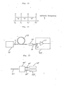
- This frequency discrimination circuit is suitably comprised of a signal separation circuit (divider), a delay circuit 23 and a double balance mixer 24 as shown in Fig. 2.
- the delay time of the delay circuit 23 can be expressed substantially as follows: where n is an odd number.
- the input/output characteristics of this frequency discriminator is as shown in Fig. 3 ⁇ a> and which exhibits desired characteristics. If the output is V and the input frequency is f, Vacos(2 ⁇ f ⁇ ).
- the output signal (voltage) 17 of this frequency discrimination circuit is applied to a voltage current conversion circuit 18 to obtain a current signal 19. This signal current 19 is added to a driving current 20 of the semiconductor laser 2.
- the voltage-current conversion circuit 18 then generates a current 19 corresponding to the signal 17, which is added to the driving current 20 to raise the optical frequency f 2 of the semiconductor laser 2.
- the current 19 in this case is a negative current and makes the driving current 20 small and f 2 high.
- the optical frequency difference f 2 - f, between the two semiconductor lasers 1 and 2 is kept at f s .
- f 1 becomes high
- the output 17 of the frequency discrimination circuit 16 generates a positive voltage so that the optical frequency f 2 of the semiconductor laser 2 becomes low.
- f 1 - f 2 becomes all the more greater and comes away from f s .
- f, - f 2 can be set to the predetermined value f s by employing any one of the following four methods.
- this embodiment can be applied similarly to a multi-electrode semiconductor laser.
- the signal current 19 may be applied directly to one or a plurality of electrodes of the multi-electrode laser.
- this embodiment is the system which applies negative feedback to the driving current, the embodiment can accomplish a frequency separation stabilization system which provides a quick frequency response of the feedback system and can follow a sharp optical frequency change.
- this embodiment uses a combination of a semiconductor laser 25, an optical system 26, and a mirror 27 shown in Fig. 4 ⁇ a>; the combination of the semiconductor laser 25 and an optical fiber 28 shown in Fig. 4 ⁇ b>; or the combination of the semiconductor laser 25, an optical system 24 and a diffraction grating 29 shown in Fig. 4 ⁇ c>.
- the driving current 20 on which the control current 19 is superposed is applied to the semiconductor laser 25.
- This embodiment provides the effect that a light source having a narrow spectral line width can be obtained.
- the third embodiment will be explained with reference to Fig. 4.
- this embodiment uses the combination of the semiconductor laser 25 and the external mirror or the optical fiber or the diffraction grating in the same way as in the second embodiment, this embodiment stabilizes the frequency separation by changing the length 1 between the semiconductor laser 25 and the mirror 27 or the optical fiber 28 or the diffraction grating 29 of the light source so as to change the optical frequency.
- the optical frequency is changed by changing the angle 0 as the optical axis by the diffraction grating by use of the output signal so as to stabilize the frequency separation.
- the distance 1 or the angle 9 can be changed by driving the mirror 27, the optical fiber 28, or the diffraction grating 29 by a piezo device.
- the optical frequency is changed by applying the output signal 17 of the control circuit 22 of Fig. 1 to the driving circuit of the piezo device so that frequency separation can be stabilized.
- the fourth embodiment will be explained with reference to Fig. 5.
- the output voltage 17 of the control circuit 22 is compared with a reference voltage (V o V in Fig. 5) by a differential amplification circuit 30.
- Its difference signal 31 is applied to a variable temperature device such as a Peltier device 32 of the light source 2 in order to change the temperature of the light source 2, to change the optical frequency f 2 (generally, the optical frequency drops in semiconductor lasers when the temperature is raised), and to fix the frequency separation f 2 - f 1 to the set value f s .
- the reference voltage Vo of the (+) input terminal of the differential amplification circuit 25 is of course set to 0 V.
- a laser module 33 incorporating therein integrally the light source 2 and the Peltier device 32 in a casing is hereby used.
- this embodiment provides the effect that the breakdown of the device is eliminated due to the drastic change of the driving current of the light source 2 by the control signal. Since the optical frequency has frequency-temperature characteristics of -12 GHz/° C in the semiconductor laser, there can be obtained the effect that the optical frequency can be controlled easily by frequency-current characteristics (-1GHz/rnA).
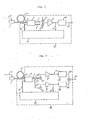
- the fifth embodiment of the present invention will be explained with reference to Fig. 6.
- the light sources 1 and 2 are herein assumed to be semiconductor lasers.
- the optical signal of the light source 1 driven by the driving current 21 passes through the optical fiber as the optical transmission path 3 and is combined with the output beam 4 of the local oscillation light source 2 by the photo- coupler 5.
- the output 7 of this photo-coupler 5 is converted to the electric signal by the optical detector 8.
- the frequency component f 2 - f 1 (where f 1 and f 2 are optical frequency of the lasers 1 and 2, respectively, and assumed to be f 2 > f 1 ) of this signal is amplified by the amplifier 9 and its part is converted to the baseband signal 35 by the demodulation circuit 34.
- Part 10 of the output of the amplifier 9 passes through the control circuit 22 and is converted to the control signal 17.
- This embodiment provides the effect that the intermediate frequency can be stabilized and the optical heterodyne communication system and the optical homodyne communication system can be accomplished while keeping stable transmission quality.
- the light sources 1 and 2 it is possible to use, as the light sources 1 and 2, other lasers; semiconductor lasers having a plurality of electrodes; and a combination of semiconductor lasers, the optical system and the mirror; optical fibers; or diffraction grating shown in Fig. 4. Needless to say, the method of Fig. 5 which changes the temperature of the local oscillation light source 2 by use of the control signal 17 can be applied to this embodiment.
- the intermediate frequency can of course be stabilized by changing the distance 1 between the semiconductor laser 25 (which serves as the local oscillator light source 2) and the mirror 27 or the optical fiber 28 or the diffraction grating, or changing again the angle 0 in the case of the diffraction grating by use of the control signal 17.
- Fig. 7 is a structural view of an optical heterodyne or optical homodyne system using a balanced type optical receiver.
- the optical signal 3 transmitted is combined with a local oscillation beam 4 by a 3 dB photo-coupler 5 and after their power is halved, they are outputted as the combined beams 7 and 6.
- These beams 7 and 6 are incident to optical detectors 8 and 8 , respectively, are converted to electric signals and added together to provide one electric signal.
- Part 10 of this signal is inputted to a control circuit 36 to stabilize the intermediate frequency and the rest are inputted to the demodulation circuit 34 to output a demodulation signal 35.
- this embodiment provides the effect that a demodulated signal having a high signal-to-noise ratio can be obtained.
- Fig. 8 is a structural view of an optical heterodyne or optical homodyne system using a polarization diversity type optical receiver 38.
- the transmitted optical signal 3 is combined with the local oscillation beam 4 by the photo- coupler 5 and its output beam 7 is separated to beams 7 and 7 having mutually crossing polarization components by a polarization separator such as a polarization prism.
- These beams are converted to electric signals by the optical detectors 8 and 8, amplified by the amplifiers 9 and 9 and demodulated by the demodulation circuits 34 and 34 to provide the demodulated signals 35' and 35.
- These demodulated signals 35 and 35 are added to provide a signal 36.
- the intermediate frequency is stabilized by the control circuit 36 using part 10 of the output of the amplifier 9.
- this embodiment can be accomplished by inputting part of the output 10 of the amplifier 9' to the control circuit 36.
- This embodiment provides the effect that degradation of the signal-to-noise ratio of the demodulated signal due to the polarization fluctuation of the optical signal 3 can be suppressed.
- the degradation described above can further be suppressed by furnishing a frequency mixer or an envelope detector contained in the demodulation circuit 34 or 34 with the amplification square characteristics.
- Fig. 9 is a structural view of an optical heterodyne or optical homodyne system using a balanced type polarization diversity receiver 40.
- the signal beam 3 propagating through the optical fiber 3 is separated to an x polarization component beam 3x and a y polarization component beam 3y having substantially crossing polarization directions with each other by the polarization separator 39.
- the polarization separator 39 include a TE-TM polarization separator produced by forming electrodes on an optical waveguide obtained by diffusing ions of Ti or the like in a polarization prism or an optical crystal exhibiting birefringence such as LiNb03.
- the local oscillation beam 4 is separated into two beams 4x and 4y whose polarization directions are substantially in agreement with 3x and 3y, respectively, by the polarization separator 39', and these beams 4x and 46 are combined with the x polarization component beams 3x and 3y by couplers 5x and 5y, respectively.
- the method of bringing the polarization directions of the signal beams 3x and 3y into substantial conformity with the local oscillation beams 3y and 4y, respectively comprises the steps of setting the angle and position of the local oscillator optical source so that the optical power of the output beam 4x is equal to that of the output beam 4y, then observing the detection output of the optical heterodyne (or optical homodyne), that is, the output amplitude of the amplifiers 9x and 9y while keeping this state (the relative position between the polarization beam splitter 39 and the local oscillator optical source 2), and rotating the polarization beam splitter 39 or the combination of the polarization beam splitter 39' with the local oscillator optical source 2 so that the output amplitude becomes maximal.
- the polarization directions of the beams 3x and 4x can be brought into substantial conformity with the polarization directions of the beams 4x and 4y, respectively.
- Another method of accomplishing the local oscillation beams 4x and 4y comprises inserting a polarization control device into an optical path between the local oscillator optical source 2 and the polarization beam splitter 39' and inserting another polarization control device into the optical paths from the two outputs of the polarization beam splitter 39 to the inputs of the photo-couplers 5x and 5y.
- the beam leaving the local oscillator optical source 2 controls the polarization directions so that the output power from the polarization beam splitter 39 is made equal by the polarization control device.
- Control is effected by the polarization control device so that polarization beam component 3x of the signal beam and the polarization beam directions of the two output beams from the polarization control device 39 are substantially in agreement with the polarization beam directions of the x polarization beam component 3x and y polarization beam component 3y.
- This control method observes the detection output of the optical heterodyne (or the optical homodyne), that is, the output amplitudes of the amplifiers 9x and 9y, and sets the polarization beam control device so that the output amplitudes become maximal.
- An example of the polarization beam control device is an optical fiber whose shape is turned to a circular coil-like form.
- the two outputs 7x and 6x (or 7y and 6y) of the two optical couplers 5x and 5y are converted to the electric signals by the two optical detectors 8x and 8x' (or 8y and 8y but at this time, optical heterodyne (or homodyne) detection occurs.
- the electric signals are added and amplified by the amplifier 9x (or 9y) and the baseband signal 35x (or 35y) is obtained by the demodulation circuit 34x (or 34y).
- the demodulation circuit 34x is not necessary in the case of the optical homodyne detection.
- the demodulation circuit may include a delay detection circuit having a delay device and a multiplier, or an envelope detection circuit having a bandpass filter and an envelope detector.
- the outputs 35x and 35y of the demodulation circuits 34x and 34y are added to obtain a signal 36.
- This embodiment provides the effects of suppressing the intensity noise contained in the local oscillation beam 4 and of preventing deterioration of the signal-to-noise ratio. Furthermore, this embodiment provides the effect that the degradation of the signal-to-noise ratio of the demodulation signal due to the polarization beam fluctuation of the optical signal 3 can be checked. This degradation can be further suppressed by furnishing the frequency mixer or the envelope detector contained in the demodulation circuit 34 or 34 with the amplitude square characteristics.
- Fig. 10 shows the optical frequency separation stabilization system of four light sources 1, 2, 1 and 2 .
- the beams of the light sources 1 and 2 are combined by the photocoupler 5.
- the optical frequency separation between the light sources 1 and 2 is stabilized by utilizing part 7 of the output beam by the same means as that of the first embodiment.
- the optical frequency separation between the light sources 1 and 2' is stabilized by utilizing part 7 of the combined beam by the same means as that of the first embodiment.
- the optical frequency separation between these two sets of optical sources (1 and 2) and (1' and 2') is stabilized by combining part 6, 6' of the photo-couplers 5 and 5 by a photo-coupler 5" and by changing the optical frequency of the light source 1 by utilizing part 7" of the output beam by the same means as that of the first embodiment.
- the pass band of the bandpass type amplifier 9 used thereby includes the optical frequency separation between the light sources 1 and 1
- Frequency separation stabilization of the four light sources is accomplished by the means described above.
- this embodiment provides the effect that the stable optical transmission apparatus 41 can be accomplished.
- this embodiment provides also the effect that the optical frequency gap between a plurality of light sources can be stabilized.
- the tenth embodiment will be described with reference to Figs. 10 and 11.
- Means for stabilizing the optical frequency separation between a plurality of (four in Fig. 10) light sources is the same as that of the ninth embodiment but this embodiment is characterized in that the disposition of these light sources is set in such a manner that their optical frequencies on the optical frequency axis are adjacent to one another.
- the optical frequencies of the light sources 1, 2, l' and 2 are arranged as shown in Fig. 11 ⁇ a> or ⁇ b>.
- Symbols f 1 ' f 2 ' f 1 ' and f 2 ' represent the optical frequencies of the light sources 1, 2, 1 and 2 , respectively.
- This embodiment provides an effect wherein it is not necessary to broaden the band width of the optical detectors 8, 8 and 8 and the bandpass filter type amplifiers 9, 9', 9" shown in Fig. 10.
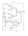
- Fig. 12 The eleventh embodiment will be explained with reference to Fig. 12.
- This embodiment represents means for keeping constant the optical frequency separation between the four light sources 1, 2, 1 and 2 .
- the beams 3, 4, 3 and 4 from the four light sources are combined by the optical multiplexers 5, 5', 5" and part 7" of its output is converted to the electric signal by the optical detector 8.
- This electric signal is amplified by the bandpass type amplifier 9.
- Fig. 13 shows the frequency characteristics of the electric signal described above.
- f 1 , f 2 , f 1 ' and f2 represent the optical frequencies of the light sources 1, 2, 1 and 2, respectively.
- the band 46 of the amplifier 9 is set so as to amplify only f 2 - f 1 .
- the signal processing from here to the acquisition of the signal 19 is the same as that of the first embodiment.
- This signal passes through the switch 19, and is added to the driving current of the light source 2 so that the optical frequency separation is stabilized between the light sources 1 and 2 by the same operation as that of the first embodiment.
- the amplification band of the bandpass amplifier 9 is switched by the control signal 43 from 46 to 46 in Fig. 13. This can be accomplished by changing the passband of the electronically tunable bandpass filter by the control signal 43.
- the output signal of this amplifier 9 contains the frequency component f2 f 1 .
- This signal is processed in the same way as in the first embodiment.
- the output signal 12 of the oscillator 11 is switched by the control signal 44 from f s - f o to f s ' - f o .
- fs is the target value of stabilization of the frequency separation between the light sources 1 and 2'.
- the signal 19 is added to the driving current 20 by switching the switch 100 by the control signal 45 so that the optical frequency separation between the light sources 1 and 2' can be stabilized.
- the amplification band of the bandpass amplifier 9 is switched by the control signal 43 from 46 to 46" in Fig. 13. Accordingly, the output signal of the amplifier 9 contains the frequency component f 1 ' -f 1 .
- This signal is processed in the same way as in the first embodiment.
- the output signal 12 of the oscillator 11 is switched by the control signal 44 from fs - f o to f s " - f o .
- fs is the target value of stabilization of the optical frequency separation between the light sources 1 and 1
- the signal 19 is applied to the driving current 20" by switching the switch 100 by the control signal 45 so that the optical frequency separation between the light sources 1 and 1 can be stabilized.
- the optical frequency separation of all the light sources 1, 1 , 2 and 2 can be kept constant by sequentially repeating the simultaneous switching operations of the amplification band of the amplifier 9, the oscillation frequency of the-oscillator 11 and the switch 100 by the control signals 43, 44, 45.
- the control signals 43, 44 and 45 are generated by the controller 42.
- This embodiment provides the effect that only one system is necessary as the control system 101 in order to keep the optical frequency gaps between three or more light sources constant.
- the second, third and fourth embodiments may be used as the frequency separation stabilization system in this embodiment.
- Figs. 12 and 14 Means for stabilizing the optical frequency separation between a plurality (four in Fig. 12) of light sources is the same as the one used in the eleventh embodiment but the set values f s , fs and fs of the plurality of optical frequency separation are mutually different as , shown in Fig. 14 and this is the characterizing feature of this embodiment.
- fi, fi , f 2 and f2 are the optical frequencies of the light sources 1, 1', 2 and 2 , respectively.
- f s , fs and fs are all different from one another, two or three frequencies of f, - f 2 , f 1 ' - fi and f 2 ' - f 1 ' do not superpose with one another and there can be obtained the effect that the periodic fluctuation of the optical frequencies due to the frequency stabilization signal can be suppressed.
- an optical transmitter 41 for intensity modulation or frequency modulation can be accomplished by causing part 6 of the output of the optical synthesizer 5 to be incident into a transmission optical fiber. This embodiment provides such an optical transmitter.
- the light source may be other lasers, multi-electrode semiconductor lasers, the combination of the semiconductor laser with the optical system and the mirror, the optical fiber or diffraction grating shown in Fig. 4, and so forth.
- Stabilization by temperature shown in Fig. 6 may be used as means for stabilizing the frequency separation.
- Another example of this embodiment is represented by 41 in Fig. 10.
- Reference numeral 41 in Fig. 12 represents still another example.
- This embodiment provides an optical transmission apparatus for wavelength multiplexing or frequency multiplexing with stabilized frequency separation.
- Reference numeral 41 in this drawing represents the transmission apparatus described in the thirteenth embodiment.
- the output beam 6 of this optical transmission apparatus 41 passes through the optical fiber 47, and are separated to a beam of each wavelength by the optical multi/ demultiplexer 48 and its optical output 50 is received by the optical receiver 49.
- the optical output 50 of the optical multiplexer/demultiplexer 48 is one of the wavelengths transmitted by transmission apparatus 41 (or optical frequency).
- the optical multi/demultiplexer produces a number of outputs corresponding to the number of the wavelengths (or frequencies) to be multiplexed which are received from the optical transmission apparatus and in this case, one each optical receiver 49 is necessary for each output. (See Fig. 16 where two receivers are required.)
- the optical signal in this embodiment is the intensity-modulated beam and the optical receiver 49 is a direct detection optical receiver consisting at least of the optical detector 51 and an amplifier.
- This embodiment provides a wavelength multiplexing or optical frequency multiplexing communication system and a communication apparatus with stabilized optical frequency separation.
- optical transmitters such as 41 in Fig. 1 or 41 in Fig. 12 may be used as the optical transmitter in Fig. 15.
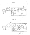
- the fifteenth embodiment will be explained with reference to Fig. 17.
- the beam 6 from the transmitter 41 of the thirteenth embodiment passes through the optical fiber 47 and the optical output 54 is combined with the beam 55 from the local oscillator optical source 56 by the photo-coupler 53.
- the output 57 of the photo-coupler 53 is subjected to optical heterodyne or optical homodyne detection by the optical detector 58 and the intermediate frequency signal is amplified by the amplifier 59 and converted to the baseband signal by the demodulation circuit 34.
- the optical signal of this embodiment is the amplitude-modulated. frequency-modulated or phase-modulated beam.
- This embodiment provides a wavelength multiplexing or optical frequency multiplexing communication system and communication apparatus with stabilized optical frequency separation.
- optical transmitters such as 41 in Fig. 1 or 41 in Fig. 12 may be used as the optical transmitter in Fig. 17.
- the sixteenth embodiment will be explained with reference to Fig. 18.
- This embodiment is characterized in that a balanced type receiver 61 is used in place of the optical heterodyne or optical homodyne receiver 60 of the fifteenth embodiment.
- This embodiment relates to the combined system . of the transmitter 41 and the receiver 60 and its transmitter.
- the structure and operation principle of the balanced type receiver are explained in the sixth embodiment.
- optical transmitters such as 41 in Fig. 1 or 41 in Fig. 12 may be used as the optical transmitter of this embodiment.
- this embodiment provides a system capable of obtaining a demodulated signal having a high signal-to-noise ratio, and a transmitter for the system.
- This embodiment uses a polarization diversity receiver 62 as the optical heterodyne or homodyne receiver 62.
- the structure and operation principle of the polarization diversity receiver are explained already with reference to the seventh embodiment.
- This embodiment relates to the combined system of the transmitter 41 with the receiver 61 and its transmission apparatus.
- other optical transmitters such as 41 in Fig. 1 or 41 in Fig. 12 may be used as the optical transmitter of this embodiment.
- This embodiment effectively prevents degradation of the signal-to-noise ratio of the demodulated signal 36 due to polarization fluctuation of the optical fiber output 54. Furthermore, the embodiment provides a communication system and its promoter capable of further suppressing the degradation of signal to noise can be ratio by furnishing the frequency mixers or the envelope detectors contained in the demodulation circuits 34 and 34 with the amplitude square characteristics.
- the eighteenth embodiment will be explained with reference to Fig. 20.
- This embodiment uses a balanced type polarization diversity receiver 63 as the optical heterodyne or homodyne receiver.
- the structure and operation principle of the balanced type polarization diversity receiver are explained already in the eighth embodiment.
- This embodiment relates to the combined system of the optical transmitter 41 and the receiver 63 and its transmission apparatus.
- the optical transmitter of this embodiment may be other optical transmitters such as 41' in Fig. 1 or 41 in Fig. 12.
- This embodiment provides the effect that the intensity noise contained in the beam from the local oscillator optical source 56 is extinguished and degradation of the signal-to-noise ratio can be prevented. Furthermore, the embodiment provides the effect that degradation of the signal-to-noise ratio of the demodulated signal due to the polarization fluctuation of the optical signal 54 can be suppressed. Still further, the embodiment provides the effect that the degradation can further be suppressed by furnishing the frequency mixer or the envelope detectors contained in the demodulation circuit 34 or 34 with the amplitude square characteristics.
- n optical fibers 471, 472, ... , 47n are shown extended from a center station 64 to n stations 651, 652, ... , 65n.
- the center station 64 stores n optical transmitters 411, 412, ... , 41n and these optical transmitters are the aforementioned transmitters 41, 41' or 41".
- At least one optical receiver 601, 602, ... , 60n exists in other station 651, 652, ... , 65n and these optical receivers are the aforementioned optical receiver 49, 60, 61, 62 or 63.
- the wavelength-multiplexed or frequency-multiplexed beams are transmitted from the center station 64 to the other stations 651, 652, ... , 65n and the other stations 651, 652, ... , 65n receive the information by any of direct detection, optical heterodyne detection and optical homodyne detection.
- This embodiment relates to this system and an apparatus for practicing the system.
- a two-way communication system can of course be accomplished by disposing the optical transmitter in at least one of the other stations 651, 652, ... , 65n so as to transmit the optical signal from the other station to the center station 64 and to receive it by the optical receiver installed in the center station.
- This embodiment provides the effect that a one-way or two-way optical communication network having stable optical frequency separation and high transmission quality can be configured.
- the optical frequency separation can be stabilized without using the optical etalon or the like so that an optical frequency stabilization system which issta- ble for a long period can be accomplished.
- optical frequency stabilization is made by utilizing part of the photo-coupler in accordance with the present invention, the beam from the light source can be utilized effectively.
- 1/2 of the photo-coupler output has been utilized conventionally in the wavelength multiplexing or optical frequency multiplexing system, but this embodiment can utilize all the photo-coupler output.
Landscapes
- Physics & Mathematics (AREA)
- Electromagnetism (AREA)
- Engineering & Computer Science (AREA)
- Computer Networks & Wireless Communication (AREA)
- Signal Processing (AREA)
- Condensed Matter Physics & Semiconductors (AREA)
- General Physics & Mathematics (AREA)
- Optics & Photonics (AREA)
- Optical Communication System (AREA)
- Semiconductor Lasers (AREA)
Applications Claiming Priority (2)
| Application Number | Priority Date | Filing Date | Title |
|---|---|---|---|
| JP63188413A JPH0239131A (ja) | 1988-07-29 | 1988-07-29 | 周波数間隔安定化方法、光ヘテロダイン又は光ホモダイン通信方法 |
| JP188413/88 | 1988-07-29 |
Publications (3)
| Publication Number | Publication Date |
|---|---|
| EP0352747A2 true EP0352747A2 (fr) | 1990-01-31 |
| EP0352747A3 EP0352747A3 (fr) | 1991-12-27 |
| EP0352747B1 EP0352747B1 (fr) | 1996-04-10 |
Family
ID=16223224
Family Applications (1)
| Application Number | Title | Priority Date | Filing Date |
|---|---|---|---|
| EP89113710A Expired - Lifetime EP0352747B1 (fr) | 1988-07-29 | 1989-07-25 | Procédé de stabilisation d'une séparation de fréquence pour communication optique hétérodyne ou homodyne |
Country Status (4)
| Country | Link |
|---|---|
| US (1) | US5396361A (fr) |
| EP (1) | EP0352747B1 (fr) |
| JP (1) | JPH0239131A (fr) |
| DE (1) | DE68926195T2 (fr) |
Cited By (15)
| Publication number | Priority date | Publication date | Assignee | Title |
|---|---|---|---|---|
| EP0591961A1 (fr) * | 1992-10-09 | 1994-04-13 | Matsushita Electric Industrial Co., Ltd. | Terminal de communication pour fibres optiques, système de communication par fibres optiques et méthode de réglage de sa longueur d'onde |
| US5532865A (en) * | 1992-10-09 | 1996-07-02 | Matsushita Electric Industrial Co., Ltd. | Fiber optic communication terminal, fiber optic communication system, and its wavelength setting method |
| FR2739236A1 (fr) * | 1995-09-27 | 1997-03-28 | Nec Corp | Circuit de stabilite de longueur d'onde |
| WO1997019504A1 (fr) * | 1995-11-17 | 1997-05-29 | The Secretary Of State For Defence | Synthetiseur de frequences |
| GB2323467A (en) * | 1995-11-17 | 1998-09-23 | Secr Defence | Frequency synthesizer |
| NL1006016C2 (nl) * | 1997-05-09 | 1998-11-10 | Univ Delft Tech | Ellipsometer met twee lasers. |
| EP0798882A3 (fr) * | 1996-03-28 | 2001-11-07 | Lucent Technologies Inc. | Procédé et appareil de surveillance et connexion des paramètres de longueurs d'ondes individuelles dans un système multi-canal à multiplexage à division de longueur d'onde |
| WO2003090385A3 (fr) * | 2002-04-17 | 2004-06-17 | Hrl Lab Llc | Procédé et appareil de synthèse de fréquences |
| US6867904B2 (en) | 2002-04-17 | 2005-03-15 | Hrl Laboratories, Llc | Integrated optical circuit for effecting stable injection locking of laser diode pairs used for microwave signal synthesis |
| US6963442B2 (en) | 2002-04-17 | 2005-11-08 | Hrl Laboratories, Llc | Low-noise, switchable RF-lightwave synthesizer |
| US7085499B2 (en) | 2001-11-15 | 2006-08-01 | Hrl Laboratories, Llc | Agile RF-lightwave waveform synthesis and an optical multi-tone amplitude modulator |
| US7499653B2 (en) | 2003-07-14 | 2009-03-03 | Hrl Laboratories, Llc | Multiple wavelength photonic oscillator |
| US7650080B2 (en) | 2001-11-15 | 2010-01-19 | Hrl Laboratories, Llc | Method and apparatus for waveform generation |
| KR200447428Y1 (ko) * | 2007-02-23 | 2010-01-25 | (주) 영진기획 | 태양전등이 구비되는 버스승강장 표지판 |
| US7822082B2 (en) | 2004-01-27 | 2010-10-26 | Hrl Laboratories, Llc | Wavelength reconfigurable laser transmitter tuned via the resonance passbands of a tunable microresonator |
Families Citing this family (34)
| Publication number | Priority date | Publication date | Assignee | Title |
|---|---|---|---|---|
| JP2798526B2 (ja) * | 1991-06-20 | 1998-09-17 | 富士通株式会社 | 周波数弁別器 |
| JP3184359B2 (ja) * | 1993-03-19 | 2001-07-09 | 富士通株式会社 | 半導体レーザ制御方法および半導体レーザ制御装置 |
| JP3534443B2 (ja) * | 1994-07-06 | 2004-06-07 | 浜松ホトニクス株式会社 | 光周波数混合装置 |
| US5717708A (en) * | 1995-11-09 | 1998-02-10 | Mells; Bradley | Method and apparatus of stabilizing a semiconductor laser |
| AU4144497A (en) | 1996-05-17 | 1997-12-05 | Uab Research Foundation | Semiconductor laser with a superbroadband or multiline spectral output |
| DE19640292C1 (de) | 1996-09-30 | 1998-05-28 | Siemens Ag | Verfahren und Anordnung zur Erzeugung eines optischen Frequenzreferenzsignals |
| DE19734957C1 (de) * | 1997-08-13 | 1998-12-24 | Lucent Tech Network Sys Gmbh | Verfahren und Anordnung zur Wellenlängenstabilisierung für mehrkanalige optische Übertragungssysteme |
| JPH1174847A (ja) | 1997-08-28 | 1999-03-16 | Matsushita Electric Ind Co Ltd | Fm変調装置 |
| DE19845701A1 (de) * | 1998-10-05 | 2000-04-06 | Palme Dieter | Anordnungen zur Überwachung der Performance von DWDM-Mehrwellenlängensystemen |
| EP0959571B1 (fr) * | 1998-10-22 | 2001-08-29 | Contraves Space AG | Dispositif pour la réception homodyne de signaux optiques modulés par déplacement de phase |
| US6483956B1 (en) | 1999-08-13 | 2002-11-19 | California Institute Of Technology | Fiber frequency locker |
| US6407846B1 (en) | 2001-03-16 | 2002-06-18 | All Optical Networks, Inc. | Photonic wavelength shifting method |
| US20020131100A1 (en) * | 2001-03-16 | 2002-09-19 | Myers Michael H. | Method for photonic wavelength error detection |
| US20020131125A1 (en) * | 2001-03-16 | 2002-09-19 | Myers Michael H. | Replicated-spectrum photonic transceiving |
| EP1262752B1 (fr) | 2001-05-17 | 2005-08-03 | THORLABS GmbH | Polarimètre à fibre, son utilisation, ainsi qu'une méthode polarimétrique |
| US7495765B2 (en) * | 2001-05-17 | 2009-02-24 | Thorlabs Gmbh | Fiber polarimeter, the use thereof, as well as polarimetric method |
| US6865345B2 (en) * | 2001-08-28 | 2005-03-08 | Agilent Technologies, Inc. | Frequency translating devices and frequency translating measurement systems that utilize light-activated resistors |
| US20040208646A1 (en) * | 2002-01-18 | 2004-10-21 | Seemant Choudhary | System and method for multi-level phase modulated communication |
| GB2387961B (en) * | 2002-04-25 | 2006-06-21 | Bookham Technology Plc | Frequency locker |
| US7099073B2 (en) * | 2002-09-27 | 2006-08-29 | Lucent Technologies Inc. | Optical frequency-converters based on group III-nitrides |
| US6986693B2 (en) * | 2003-03-26 | 2006-01-17 | Lucent Technologies Inc. | Group III-nitride layers with patterned surfaces |
| US20050100344A1 (en) * | 2003-11-06 | 2005-05-12 | Hogan Josh N. | System for coherent optical communication |
| JP2005138143A (ja) * | 2003-11-06 | 2005-06-02 | Disco Abrasive Syst Ltd | レーザ光線を利用する加工装置 |
| US7379672B2 (en) * | 2004-02-12 | 2008-05-27 | Northrop Grumman Corporation | Photonic RF distribution system |
| WO2006119795A1 (fr) * | 2005-05-13 | 2006-11-16 | Pirelli & C. S.P.A. | Procede et systeme de communications optiques a surveillance du rapport signal optique bruit par tomographie homodyne optique |
| US7406269B2 (en) * | 2006-03-10 | 2008-07-29 | Discovery Semiconductors, Inc. | Feedback-controlled coherent optical receiver with electrical compensation/equalization |
| US7809284B2 (en) * | 2006-06-23 | 2010-10-05 | Alcatel-Lucent Usa Inc. | System and method for receiving coherent, polarization-multiplexed optical signals |
| US7952109B2 (en) * | 2006-07-10 | 2011-05-31 | Alcatel-Lucent Usa Inc. | Light-emitting crystal structures |
| US7266257B1 (en) | 2006-07-12 | 2007-09-04 | Lucent Technologies Inc. | Reducing crosstalk in free-space optical communications |
| ES2326152B1 (es) * | 2006-12-29 | 2010-06-29 | Universitat Politecnica De Catalunya (Upc) | Receptor homodino para comunicaciones opticas con procesado a posteriori. |
| KR101809338B1 (ko) * | 2013-01-15 | 2018-01-18 | 더 리젠츠 오브 더 유니버시티 오브 캘리포니아 | 휴대용 브로드밴드 확산 광학 분광 이미징(dosi) |
| EP3264639B1 (fr) * | 2015-03-19 | 2019-05-08 | Huawei Technologies Co., Ltd. | Procédé et dispositif d'étalonnage de fréquence de signal optique |
| WO2018156132A1 (fr) * | 2017-02-23 | 2018-08-30 | Halliburton Energy Services, Inc. | Système de détection acoustique distribué équipé d'un dispositif de commande de polarisation destiné à améliorer le rapport signal sur bruit |
| ES2900166T3 (es) * | 2017-03-21 | 2022-03-16 | Bifrost Communications ApS | Sistemas, dispositivos y métodos de comunicación óptica que incluyen receptores ópticos de alto rendimiento |
Family Cites Families (7)
| Publication number | Priority date | Publication date | Assignee | Title |
|---|---|---|---|---|
| GB2172766B (en) * | 1985-03-21 | 1988-12-21 | Stc Plc | Optical receiver |
| US4726011A (en) * | 1985-04-08 | 1988-02-16 | Itt Defense Communications, A Division Of Itt Corporation | Coherent optical fiber communication with frequency-division-multiplexing |
| GB8522821D0 (en) * | 1985-09-16 | 1985-10-23 | British Telecomm | Frequency referencing system |
| US4783852A (en) * | 1985-09-18 | 1988-11-08 | Siemens Aktiengesellschaft | Method and apparatus for acquiring information using a relative phase deviation of the optical signal of a local oscillator of a homodyne receiver |
| WO1987004572A1 (fr) * | 1986-01-28 | 1987-07-30 | British Telecommunications Public Limited Company | Controle et regulation de la stabilite d'une source de radiation |
| JP2562623B2 (ja) * | 1987-10-28 | 1996-12-11 | 国際電信電話株式会社 | ベースバンド合成法による偏波ダイバーシティ光受信方式 |
| JPH063512B2 (ja) * | 1988-02-19 | 1994-01-12 | 富士通株式会社 | コヒーレント光通信用偏波ダイバーシティ光受信装置 |
-
1988
- 1988-07-29 JP JP63188413A patent/JPH0239131A/ja active Pending
-
1989
- 1989-07-25 DE DE68926195T patent/DE68926195T2/de not_active Expired - Fee Related
- 1989-07-25 EP EP89113710A patent/EP0352747B1/fr not_active Expired - Lifetime
-
1992
- 1992-06-19 US US07/902,473 patent/US5396361A/en not_active Expired - Fee Related
Non-Patent Citations (4)
| Title |
|---|
| APPLIED PHYSICS B vol. B 35, no. 7, November 1984, HEIDELBERG, DE pages 119 - 122; WHITFORD: 'Simultaneous phase-lock of five CO2 lasers to a primary Cs frequency standard' * |
| EUROPEAN CONFERENCE ON OPTICAL COMMUNICATION 21 September 1982, CANNES, FR pages 174 - 178; STEELE ET. AL.: 'Electronic controll of a difference frequency between two semiconductor lasers' * The whole document * * |
| JOURNAL OF OPTICAL COMMUNICATION vol. 2, no. 3, September 1981, BERLIN pages 82 - 88; OKOSHI, KIMURA: 'Heterodyne-type optical communication' * |
| MOLLENAUER, WHITE "Tunable lasers (Topics in applied physics vol.59)' 1987, SPRINGER VERLAG, Berlin, De. * Page 13, paragraph b * * |
Cited By (21)
| Publication number | Priority date | Publication date | Assignee | Title |
|---|---|---|---|---|
| US5532865A (en) * | 1992-10-09 | 1996-07-02 | Matsushita Electric Industrial Co., Ltd. | Fiber optic communication terminal, fiber optic communication system, and its wavelength setting method |
| EP0591961A1 (fr) * | 1992-10-09 | 1994-04-13 | Matsushita Electric Industrial Co., Ltd. | Terminal de communication pour fibres optiques, système de communication par fibres optiques et méthode de réglage de sa longueur d'onde |
| US5861975A (en) * | 1995-09-27 | 1999-01-19 | Nec Corporation | Wavelength stability circuit |
| FR2739236A1 (fr) * | 1995-09-27 | 1997-03-28 | Nec Corp | Circuit de stabilite de longueur d'onde |
| GB2305774A (en) * | 1995-09-27 | 1997-04-16 | Nec Corp | A wavelength stability circuit |
| GB2305774B (en) * | 1995-09-27 | 1997-12-24 | Nec Corp | A wavelength stability circuit |
| GB2323467B (en) * | 1995-11-17 | 2000-02-16 | Secr Defence | Frequency synthesizer |
| GB2323467A (en) * | 1995-11-17 | 1998-09-23 | Secr Defence | Frequency synthesizer |
| WO1997019504A1 (fr) * | 1995-11-17 | 1997-05-29 | The Secretary Of State For Defence | Synthetiseur de frequences |
| EP0798882A3 (fr) * | 1996-03-28 | 2001-11-07 | Lucent Technologies Inc. | Procédé et appareil de surveillance et connexion des paramètres de longueurs d'ondes individuelles dans un système multi-canal à multiplexage à division de longueur d'onde |
| NL1006016C2 (nl) * | 1997-05-09 | 1998-11-10 | Univ Delft Tech | Ellipsometer met twee lasers. |
| WO1998052019A1 (fr) * | 1997-05-09 | 1998-11-19 | Technische Universiteit Delft | Ellipsometre equipe de deux lasers |
| US6373871B1 (en) | 1997-05-09 | 2002-04-16 | Technische Universiteit Delft | Ellipsometer with two lasers |
| US7085499B2 (en) | 2001-11-15 | 2006-08-01 | Hrl Laboratories, Llc | Agile RF-lightwave waveform synthesis and an optical multi-tone amplitude modulator |
| US7650080B2 (en) | 2001-11-15 | 2010-01-19 | Hrl Laboratories, Llc | Method and apparatus for waveform generation |
| US6867904B2 (en) | 2002-04-17 | 2005-03-15 | Hrl Laboratories, Llc | Integrated optical circuit for effecting stable injection locking of laser diode pairs used for microwave signal synthesis |
| US6963442B2 (en) | 2002-04-17 | 2005-11-08 | Hrl Laboratories, Llc | Low-noise, switchable RF-lightwave synthesizer |
| WO2003090385A3 (fr) * | 2002-04-17 | 2004-06-17 | Hrl Lab Llc | Procédé et appareil de synthèse de fréquences |
| US7499653B2 (en) | 2003-07-14 | 2009-03-03 | Hrl Laboratories, Llc | Multiple wavelength photonic oscillator |
| US7822082B2 (en) | 2004-01-27 | 2010-10-26 | Hrl Laboratories, Llc | Wavelength reconfigurable laser transmitter tuned via the resonance passbands of a tunable microresonator |
| KR200447428Y1 (ko) * | 2007-02-23 | 2010-01-25 | (주) 영진기획 | 태양전등이 구비되는 버스승강장 표지판 |
Also Published As
| Publication number | Publication date |
|---|---|
| EP0352747A3 (fr) | 1991-12-27 |
| US5396361A (en) | 1995-03-07 |
| DE68926195T2 (de) | 1996-11-28 |
| JPH0239131A (ja) | 1990-02-08 |
| DE68926195D1 (de) | 1996-05-15 |
| EP0352747B1 (fr) | 1996-04-10 |
Similar Documents
| Publication | Publication Date | Title |
|---|---|---|
| EP0352747A2 (fr) | Procédé de stabilisation d'une séparation de fréquence pour communication optique hétérodyne ou homodyne | |
| US7209664B1 (en) | Frequency agile transmitter and receiver architecture for DWDM systems | |
| EP0228888B1 (fr) | Système de transmission optique à détection cohérente et procédé | |
| US5305134A (en) | Optical frequency division multiplexing transmitter and optical frequency division multiplexing transmission apparatus | |
| KR100305258B1 (ko) | 광전송시스템및그에이용되는광송신장치및광수신장치 | |
| US8861967B2 (en) | Reconfigurable optical add/drop multiplexer and reconfigurable optical add/drop multiplexing method | |
| JP3000551B2 (ja) | 光電式周波数分割器回路及びその操作方法 | |
| US7376356B2 (en) | Optical data transmission system using sub-band multiplexing | |
| US6788899B2 (en) | Dynamic wavelength add/drop multiplexer for UDWDM optical communication system | |
| EP0201825A2 (fr) | Communication par fibre optique avec multiplexage à division de fréquence | |
| EP0245026A2 (fr) | Mélangeur optique hétérodyne procurant une réjection des fréquences-images | |
| CA1308440C (fr) | Methode de communication optique a diversite de polarisation et appareil utilisant cette methode | |
| JP3697350B2 (ja) | 光送信器 | |
| EP1189376A2 (fr) | Emetteur optique a multiplexage en longueur d'onde, récepteur optique a multiplexage en longueur d'onde, dispositif de transmission optique, et système de transmission optique | |
| US6909853B1 (en) | Apparatus for transferring monitor signals in photo-transfer system | |
| JPH10126341A (ja) | 光送信機及び光ネットワークシステム | |
| CN119675784A (zh) | 基于周期性光滤波器的多通道光传输装置 | |
| US6788833B1 (en) | Method and system for suppressing signal distortions associated with nonlinearity in optical fibers | |
| EP1041748A2 (fr) | Stabilisateur de fréquence pour une source lumineuse pour la communication optique | |
| JP2003258373A (ja) | 波長制御装置及び波長制御方法 | |
| KR100977921B1 (ko) | 광전송시스템 | |
| JPH09129950A (ja) | 光受信装置 | |
| EP1324105B1 (fr) | Méthode de contrôle et dispositif pour un filtre optique | |
| JP2008228206A (ja) | 光角度変調器 | |
| JPS58206245A (ja) | 光波長分割多重方式 |
Legal Events
| Date | Code | Title | Description |
|---|---|---|---|
| PUAI | Public reference made under article 153(3) epc to a published international application that has entered the european phase |
Free format text: ORIGINAL CODE: 0009012 |
|
| AK | Designated contracting states |
Kind code of ref document: A2 Designated state(s): DE FR GB |
|
| 17P | Request for examination filed |
Effective date: 19901212 |
|
| PUAL | Search report despatched |
Free format text: ORIGINAL CODE: 0009013 |
|
| AK | Designated contracting states |
Kind code of ref document: A3 Designated state(s): DE FR GB |
|
| 17Q | First examination report despatched |
Effective date: 19940310 |
|
| GRAH | Despatch of communication of intention to grant a patent |
Free format text: ORIGINAL CODE: EPIDOS IGRA |
|
| GRAA | (expected) grant |
Free format text: ORIGINAL CODE: 0009210 |
|
| AK | Designated contracting states |
Kind code of ref document: B1 Designated state(s): DE FR GB |
|
| REF | Corresponds to: |
Ref document number: 68926195 Country of ref document: DE Date of ref document: 19960515 |
|
| PGFP | Annual fee paid to national office [announced via postgrant information from national office to epo] |
Ref country code: FR Payment date: 19960716 Year of fee payment: 8 |
|
| PGFP | Annual fee paid to national office [announced via postgrant information from national office to epo] |
Ref country code: GB Payment date: 19960724 Year of fee payment: 8 |
|
| ET | Fr: translation filed | ||
| PGFP | Annual fee paid to national office [announced via postgrant information from national office to epo] |
Ref country code: DE Payment date: 19960926 Year of fee payment: 8 |
|
| PLBE | No opposition filed within time limit |
Free format text: ORIGINAL CODE: 0009261 |
|
| STAA | Information on the status of an ep patent application or granted ep patent |
Free format text: STATUS: NO OPPOSITION FILED WITHIN TIME LIMIT |
|
| 26N | No opposition filed | ||
| PG25 | Lapsed in a contracting state [announced via postgrant information from national office to epo] |
Ref country code: GB Free format text: LAPSE BECAUSE OF NON-PAYMENT OF DUE FEES Effective date: 19970725 |
|
| GBPC | Gb: european patent ceased through non-payment of renewal fee |
Effective date: 19970725 |
|
| PG25 | Lapsed in a contracting state [announced via postgrant information from national office to epo] |
Ref country code: FR Free format text: LAPSE BECAUSE OF NON-PAYMENT OF DUE FEES Effective date: 19980331 |
|
| PG25 | Lapsed in a contracting state [announced via postgrant information from national office to epo] |
Ref country code: DE Free format text: LAPSE BECAUSE OF NON-PAYMENT OF DUE FEES Effective date: 19980401 |
|
| REG | Reference to a national code |
Ref country code: FR Ref legal event code: ST |