EP0353000B1 - Obturateur pour cassette à disque, procédé et appareil de fabrication dumême - Google Patents
Obturateur pour cassette à disque, procédé et appareil de fabrication dumême Download PDFInfo
- Publication number
- EP0353000B1 EP0353000B1 EP89307490A EP89307490A EP0353000B1 EP 0353000 B1 EP0353000 B1 EP 0353000B1 EP 89307490 A EP89307490 A EP 89307490A EP 89307490 A EP89307490 A EP 89307490A EP 0353000 B1 EP0353000 B1 EP 0353000B1
- Authority
- EP
- European Patent Office
- Prior art keywords
- shutter
- disposed
- edge
- gate
- injection
- Prior art date
- Legal status (The legal status is an assumption and is not a legal conclusion. Google has not performed a legal analysis and makes no representation as to the accuracy of the status listed.)
- Expired - Lifetime
Links
Images



Classifications
-
- G—PHYSICS
- G11—INFORMATION STORAGE
- G11B—INFORMATION STORAGE BASED ON RELATIVE MOVEMENT BETWEEN RECORD CARRIER AND TRANSDUCER
- G11B23/00—Record carriers not specific to the method of recording or reproducing; Accessories, e.g. containers, specially adapted for co-operation with the recording or reproducing apparatus ; Intermediate mediums; Apparatus or processes specially adapted for their manufacture
- G11B23/02—Containers; Storing means both adapted to cooperate with the recording or reproducing means
- G11B23/03—Containers for flat record carriers
-
- B—PERFORMING OPERATIONS; TRANSPORTING
- B29—WORKING OF PLASTICS; WORKING OF SUBSTANCES IN A PLASTIC STATE IN GENERAL
- B29C—SHAPING OR JOINING OF PLASTICS; SHAPING OF MATERIAL IN A PLASTIC STATE, NOT OTHERWISE PROVIDED FOR; AFTER-TREATMENT OF THE SHAPED PRODUCTS, e.g. REPAIRING
- B29C45/00—Injection moulding, i.e. forcing the required volume of moulding material through a nozzle into a closed mould; Apparatus therefor
- B29C45/17—Component parts, details or accessories; Auxiliary operations
- B29C45/26—Moulds
- B29C45/33—Moulds having transversely, e.g. radially, movable mould parts
-
- G—PHYSICS
- G11—INFORMATION STORAGE
- G11B—INFORMATION STORAGE BASED ON RELATIVE MOVEMENT BETWEEN RECORD CARRIER AND TRANSDUCER
- G11B23/00—Record carriers not specific to the method of recording or reproducing; Accessories, e.g. containers, specially adapted for co-operation with the recording or reproducing apparatus ; Intermediate mediums; Apparatus or processes specially adapted for their manufacture
- G11B23/02—Containers; Storing means both adapted to cooperate with the recording or reproducing means
- G11B23/03—Containers for flat record carriers
- G11B23/0301—Details
- G11B23/0308—Shutters
-
- G—PHYSICS
- G11—INFORMATION STORAGE
- G11B—INFORMATION STORAGE BASED ON RELATIVE MOVEMENT BETWEEN RECORD CARRIER AND TRANSDUCER
- G11B23/00—Record carriers not specific to the method of recording or reproducing; Accessories, e.g. containers, specially adapted for co-operation with the recording or reproducing apparatus ; Intermediate mediums; Apparatus or processes specially adapted for their manufacture
- G11B23/02—Containers; Storing means both adapted to cooperate with the recording or reproducing means
- G11B23/03—Containers for flat record carriers
- G11B23/033—Containers for flat record carriers for flexible discs
- G11B23/0332—Containers for flat record carriers for flexible discs for single discs, e.g. envelopes
Definitions
- the present invention relates to a shutter for a disk cartridge including a cartridge casing rotatably accommodating a recording medium disk, e.g. a magnetic disk, a photo disk or a photo-magnetic disk.
- the shutter is made of a synthetic resin and is provided for opening and closing a read/write window formed in the cartridge casing.
- the present invention further relates to a manufacturing apparatus for the shutter and a manufacturing method thereof.
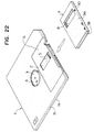
- a disk cartridge shown in Figure 22 of the accompanying drawings is one known such cartridge.
- the disk cartridge shown in Figure 22 comprises a cartridge casing 1 formed by combining two casing halves 1a and 1b together, both made of synthetic resin, and a flexible magnetic disk 2 rotatably accommodated in the casing 1.
- the magnetic disk 2 is provided at a centre portion thereof with a hub 3.
- the hub 3 is exposed through an opening 4 formed at a centre of the cartridge casing 1.
- a driving apparatus can rotate the magnetic disk 2 at a predetermined rotating speed through the hub 3.
- the cartridge casing 1 is provided at opposite sides thereof with rectangular recess portions 6.
- Read/write windows 5 are formed in the recess portions 6, into which a magnetic head can enter.
- a shutter 7 of U-shaped cross-section rides slidably astride the recess portions 6.
- the shutter 7 comprises two side plates 9a,9b and a connecting member 10 for connecting at one end the side plates 9a,9b.
- the shutter 7 further comprises a rectangular head access hole 8 of substantially the same dimension and shape as the window 5.
- the shutter 7 is elastically urged by a spring member accommodated therein (not shown) so as to close the windows 5.
- a spring member accommodated therein not shown
- the shutter is made of metal material or synthetic resin.
- the metal shutter may shave down sliding surfaces of the recess portions 6 by edge portions of the shutter 7 on sliding movement of the shutter 7 to provide shavings of the synthetic resin casing 1.
- the shavings may adhere to the surfaces of the magnetic disk 2 to cause recording and reproducing errors.
- an increased clearance is provided between the cartridge casing 1 and the shutter 7. In this case, foreign substances can easily enter from the outside into the casing 1 through the increased clearance. Accordingly, the foreign substances may adhere to the magnetic disk surfaces also to cause recording and reproducing errors.
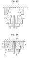
- the shutter 7 is made by the manufacturing apparatus shown in Figs. 23 and 24.
- a reference numeral 11 designates a stationary mould
- 12 designates a pair of side slide moulds
- 13 designates a core to be disposed between the side slide moulds 12 and 12′
- 14 and 14′ designate a pair of side locks
- 15 designates a cavity for the shutter
- 16 designates an ejecting pin slidably disposed in the core 13.
- the letter Z designates a mould clamping direction.
- the stationary mould 11, the side slide moulds 12, and the core 13 are so clamped together as to define thereamong the cavity 15 for the moulding operation.
- the side slide mound 12 abuts at a tapered portion 12a thereof against a tapered portion 14a of the slide lock 14 to clamp these moulds together under an appropriate clamping force.
- the moulds are held with a clamping force being applied thereto in the direction Z, and the synthetic resin is injected into the cavity 15 by means of injection means (not shown) to provide the mouldings.
- injection means not shown
- the side slide moulds 12 and 12 are separated from each other.
- The-moulded shutter 7 mounted on the core 13 is ejected therefrom by means of the ejecting pin 16.
- the force applied to the side locks 14 and 14′ may be nonuniform, or the abutting force against the core 13 from one side slide mould 12 may differ from that from the other side slide mould 12 due to dispersion of manufacturing accuracy. If the abutting forces differ from each other, the core 13 may incline towards either side thereof since the core 13 is thin (about 2.8 mm). As a result, the side plates 9a and 9b of the shutter 7 differ from each other in the thickness thereof. Further, molten resin enters between the side slide mould 12 and the core 13 which are abutted each other with lower abutting force to provide the mouldings with moulding flash.
- the core 13 is provided therein with a small straight bore for the ejecting pin 16.
- the core has, for example, a thickness of about 2.8 mm and a length of about 35 mm. Therefore, it is hard to provide the small straight bore (for example, 1.5 mm diameter) to the core 13 from the processing technical point of view.
- the ejecting pin 16 pushes the moulded shutter 7 at an inner wall surface of the connecting member 10 thereof to remove it from the core 13.
- a part of the connecting member 10 projects outwards or a moulding flash projects inwards from the inner wall surface of the connecting member 10.
- the shutter 7 is limited in the slide movement thereof by the stepped parts of the recess portions 6 of the casing 1.
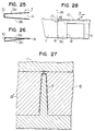
- the side plates 9a and 9b of the shutter 7 extend apart from each other to widen an opening end A , the shutter 7 can slide beyond the stepped part ( Figure 25). Therefore, the hole 8 does not align with the windows 5 thus to disable the head from entering the windows 5.
- a conventional shutter is formed to be of a U-shaped cross-section by bending a thin metal plate, for example, a stainless steel plate of a thickness of 0.2 mm.
- a thin metal plate for example, a stainless steel plate of a thickness of 0.2 mm.
- the metal shutter may readily shave down the synthetic resin casing and may be readily detached from the casing on drop impact.
- the shutter is formed integrally by means of injection moulding of synthetic resin.
- the moulds used in the injection moulding are so arranged, as shown in Fig. 27, that a core 13 is supported at opposite sides thereof by side slide moulds 12 and 12′ to define thereamong a longitudinal cavity for the shutter, and a stationary mould 11 is mounted on these moulds.
- the supporting force for the core 13 is one perpendicular to the clamping force for clamping the moulds 12 and 12′. Namely, such supporting force is one transmitted through the locking blocks and an angular pin and is not sufficient to withstand the injection pressure.
- the injection pressure of resin at the side of the core 13 into which resin is first injected urges the core 13 towards the other side. This causes a difference in thickness between the side plates.
- a cartridge casing 1 of a magnetic disk cartridge to which a conventional synthetic resin shutter 7 is mounted is provided with a recess 17.
- a pin 18 of a recording/reproducing apparatus enters into the recess 17 to abut against an edge of the shutter 7 and moves it from a closed position (shown in the drawings) to an open position in a direction X to open the hole 8.
- a gate is disposed at an edge of the connecting member 10 adjacent to the hole 8. Therefore, after the moulding, a tapered gate mark 19 is left at the edge of the connecting member 10 to extend towards the recess 17.
- the gate mark 19 prevents the pin 18 from engaging with the shutter 7 and may ride on the side plate 9a or 9b of the shutter 7. It becomes impossible to obtain reliability of the movement of the shutter 7.
- An object of the present invention is to provide a disk cartridge shutter which can be moulded without defective moulding and with a high efficiency of moulding, and to provide apparatus for, and a method of, manufacturing such a shutter.
- Another object of the present invention is to provide a shutter for a disk cartridge, which can be so moulded that the side plates thereof are somewhat in contact with each other or are close to each other to narrow an opening of the shutter, and to provide a manufacturing apparatus for such shutter.
- EP-A-0 201 870 discloses a shutter, apparatus for manufacturing the shutter and a method of manufacturing the shutter as referred to in the prior art portions of claims 1, 6 and 11, respectively.
- the shutter of the present invention as defined in claim 1, and as made in the apparatus and using the method of the invention as defined in claims 6 and 11 is advantageous in that both side plates reliably have the same thickness due to the method of moulding with ejection being transversely of the connecting plate between the two side plates.
- This improved construction provides a shutter for a disk cartridge, which can present a high reliability of movement thereof.
- the draft angle defined by opposite side surfaces of the slide core is held between 2° and 8°. According to this, due to the difference of cooling rate, the shutter is so moulded that free ends of the side plates, which define an opening end, come into contact with each other or come close to each other to narrow the opening end.
- the slide core for forming a space defined by the side plates of the shutter is slidable in a direction perpendicular to a mould opening direction, it becomes possible directly to support the slide core by means of the mould clamping force, thereby effectively preventing the side plates from differing from each other in the thickness thereof and improving the productivity of the shutter moulding.
- the shutter has opposite edges, one on which a shutter opening member of recording/reproducing apparatus is adapted to abut, and the other edge which is the only edge provided with a gate mark, or has a first injection gate disposed at a portion corresponding to one end of the shutter on which a shutter opening member of a recording/reproducing apparatus is adapted to abut, and a second injection gate disposed at a portion corresponding to the other edge of the shutter opposite to the one edge thereof, the second injection gate having a passage cross-section larger than that of the first injection gate.
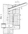
- an injection moulding apparatus for a shutter includes a movable mould 21, a stationary mould 22 disposed above the movable mould 21, and a slide core 23 disposed between the moulds 21 and 22 to define therebetween a cavity 24 for a shutter.
- the mould 22, the slide core 23 and the mould 21 are to be clamped up in a claiming direction Z in order.
- the apparatus further includes an angular pin 25 and resin injection means 26.
- the base portion 28 is provided with a bore 29 through which the angular pin 25 extends. The slide core 23 can move along the angular pin 25.
- the injection means 26 injects molten synthetic resin, e.g. polypropylene, as moulding compound into the cavity 24 through a passage 27.
- molten synthetic resin e.g. polypropylene
- a moulded shutter 34 is retained on the movable mould 21.
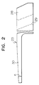
- the shutter 34 has opposite side plates 35a and 35b, and a connecting plate 36 connecting one ends of the side plates 35a and 35b.
- a reference numeral 31 designates an ejection pin consisting of an ejecting plate portion 32 and a cylindrical body portion 33 from which the ejecting plate portion 32 extends.
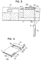
- the ejection pin 31 is so disposed that an end of the ejecting plate portion 32 faces towards and abuts on a portion of the side plate 35a under a connecting portion 36a between the side plate 35a and the connecting plate 36.
- the ejection pin 31 pushes up the shutter 34 to remove it from the movable mould 21.
- the shutter 34 is, as shown in Fig. 4, provided on the side plate 35a thereof with two elongate ejection marks 37 and 37 which are somewhat recessed and each of which is placed on a portion including at least the connecting portion 36a.
- the ejecting plate portion 32 is so designed that a width W of the ejection mark 37 becomes substantially identical to a thickness t of the connecting plate 36.
- the ejecting plate portion 32 does not completely face to the connecting portion 36a only, but extend over the connecting portion 36a and the side plate 35a.
- the shutter can be ejected by means of means of pushing up a portion thereof including at least the connecting portion 36a by the ejection pin 31, the connecting plate 36 withstands an ejecting force from the ejection pin 31, as clearly seen from Fig. 3, on the ejection to prevent the shutter from deforming and to eject it from the mould 21 surely.
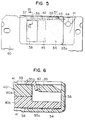
- the cartridge casing 40 consists of two casing halves 40a and 40b. Each of the halves 40a and 40b is provided on a predetermined portion thereof with a recess portion 41 which restricts the movement of the shutter within a predetermined range.
- a guide groove 42 is provided in the casing 40 to extend on the casing half 40a.
- a guide claw 39 extending inwardly from the side plate 35a with a predetermined inclination angle cooperates with the guide groove 42 to control the sliding movement of the shutter 34.
- the shutter 34 is elastically urged to close a magnetic head access hole 45 by means of a spring force of a spring 44.
- the spring 44 is engaged at one end thereof with a projection 43 projecting from an inner surface of the connecting plate 36 and at the other end thereof with an inner surface of the casing 40.
- the shutter 34 is tightly and slidably mounted on the recess portion 41 as well as is certainly stopped at opposite stepped portions, i.e. both ends of the recess portion 41.
- a magnetic disk cartridge according to another embodiment of the invention includes a cartridge casing 40, a magnetic disk 46 rotatably accommodated within the casing 40, and a shutter 34.
- the casing 40 consists of two casing halves 40a and 40b.
- the casing 40 is provided on opposite surfaces thereof with recess portions 41 and on an end face adjacent to the recess portions 41 with a guide groove 42. Further, the casing 40 is provided on the recess portions 41 with a head access hole 45 through which a magnetic head accesses the magnetic disk 46.
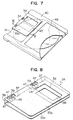
- two guide projections 39 are provided in the connecting plate 36 to extend perpendicular thereto. Both ends 48 and 48 of each of the guide projection 39 expand outwards in opposite directions perpendicular to the guide projection 39. The both ends 48 are received within the guide groove 42 so as to cooperate therewith to control the slide movement of the shutter 34.
- a reference numeral 50 designates a runner block.
- the slide core 49 is adapted to move along the angular pin 25 to remove from the movable mould 21 in a direction Y perpendicular to the mould clamping direction Z .
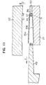
- the movable and the stationary moulds 21 and 22 are provided with projections 51 and 51, respectively. As clearly shown in Fig. 12, when clamped, these projections 51 and 51 abut to each other to form therebetween a cavity 39c for the guide projection 39. Accordingly, the shutter 34 is provided with windows 47 corresponding to the guide projections 39, which are formed by the projections 51. Further, the moulds 21 and 22 are provided with recess portions 52 and 52 for directly receiving a part of the slide core 49 (Fig. 12). The mould clamping force applied to the moulds 21 and 22 is directly transmitted to the slide core 49 so as to retain a tapered end portion of the slide core 49. According this, the slide core is prevented from being deflected by means of pressure of injected molten resin.
- This mould arrangement is applicable not only to the above-mentioned shutter which includes a guide projections projected from the connecting plate 36, but also to the shutter which includes a guide projections projected from the side plate 35a or 35b as shown in Fig. 6.
- a mould arrangement of an injection moulding apparatus for two-impression include gates 53 through which molten resin flowing in a runner 56 is injected into cavities for the shutters.
- the gate 53 is so disposed as to communicate at first with a part of the cavity corresponding to an edge 55b of the moulded shutter 34 opposite to an edge 55a thereof to which a shutter opening member 54 of a recording/reproducing apparatus is adapted to abut, namely an edge 55b apart from a hole 38.
- the gate 53 has a width (a dimension measured in a direction perpendicular to the drawing sheet) substantially identical to a height of the connecting plate 36.
- a gate mark is formed only in one edge 55b of the shutter 34, opposite to the other edge 55a to which the shutter opening member 54 is to be abutted. According this, when the shutter 34 is to be moved by means of the member 54, the gate mark never prevents the opening member 54 from engaging with the other edge 55a.
- the opening member 54 can engage with the edge 55a without riding onto the connecting plate 36, thereby surely moving the shutter to open the head access hole of the cartridge casing.
- the shutter 34 is provided at outer surfaces thereof with a plurality of straight projections 57 and of grooves 58 which are formed alternately.
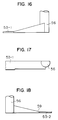
- a mould arrangement of an injection moulding apparatus for two-impression includes a first gate 53-1 and a second gate 53-2 for each shutter, through which molten resin flowing in runners 56 is injected into a cavity for the shutter.
- the first gate 53-1 is so disposed as to communicate at first with a part of the cavity corresponding to an edge 55b of the moulded shutter 34 opposite to an edge 55a thereof which is adjacent to the hole 38a.
- the second gate 53-2 is so disposed as to communicate at first with a part of the cavity corresponding to the edge 55a of the moulded shutter 34.
- the molten resin is injected into a cavity simultaneously through the first gate 53-1 and the second gate 53-2 to mould the shutter 34.
- the first gate 53-1 has a cross-sectional area S1 greater than that S2 of the second gate 53-2 (S1 > S2).
- S1 greater than that S2 of the second gate 53-2
- the second gate 53-2 is provided with a constriction portion 59 to narrow the cross-sectional area thereof.
- no constriction portion 59 is provided in the first gate 53-1.
- the plan shape dimension of the second gate portion is identical to that of the first gage portion shown in Fig. 17.
- the gate mark formed on the edge 55a of the moulded shutter is necessarily smaller than that on the edge 55b.
- the periphery of the hole 38 is generally deformable under moulding pressure due to a lower rigidity thereof. According to this embodiment, if the injection is so controlled that the moulding pressure is applied to the first gate 53-1 more longer and is applied to the second gate 53-2 more shorter by means of shortening a gate seal time period, it becomes possible to improve the rigidity in the periphery of the hole 38 to prevent deformation thereof.
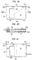
- the thicknesses in two parts 60 and 61 of the side plate 35a and 35b of the shutter 34 differ from each other, into which parts 60 and 61 the side plate is divided by a diagonal line (broken line).
- the fluidity resistance of molten resin in the part 60 is higher than that in the part 61 because an opening for the hole 38 is formed in the part 60 to generate two parts 62 and 62 of narrow width.
- the thickness of the side plate in the part 60 is substantially larger than that in the part 61.
- the thickness of the side plate is generally uniform and is t1 .
- the thickness of the side plate is gradually increased towards the side end of the shutter.
- the thickness in the side end of the shutter is t2 which is somewhat greater than t1
- the thickness in the boundary portion between the parts 60 and 61 is t1 . According this, it can be possible to eliminate generation of defective moulded shutter.
- this shutter 34 is also provided at outer surfaces thereof with a plurality of straight projections and of grooves as the shutter shown in Fig. 13 is.
- the side plate is divided into two parts 60 and 61 by a bisector (broken line).
- a bisector broken line
- an ejection mark is provided on a part of the outer surface of either side plate of the shutter including a part corresponding to the connecting portion of the connecting plate.
- the slide core becomes simple and then readily manufactured. Furthermore, it can be possible to shorten a cooling time period to improve an efficiency of moulding of the shutter with decrease of the defective one.
- the mould clamping force is directly applied to the slide core to support it, the deflection of the slide core on the moulding is prevented, thereby eliminating the thickness deviation in the side plates of the shutter and the moulding flash.
- the shutter moulded with a high accuracy in the dimension thereof can be obtained.
- the gate mark is provided only on an edge of the shutter opposite to an edge thereof to which a shutter opening member is adapted to abut. Therefore, it is eliminated that the gate mark prevents the opening member from engaging with side end of the shutter and then prevents the driving of the shutter. Improved is a reliability on the driving of the shutter to open the head access window of the cartridge casing.
Landscapes
- Engineering & Computer Science (AREA)
- Manufacturing & Machinery (AREA)
- Mechanical Engineering (AREA)
- Moulds For Moulding Plastics Or The Like (AREA)
Claims (15)
- Obturateur (34) en résine de synthèse destiné à une cartouche de disque (40) pour ouvrir et fermer un trou (45) d'accès de tête formé dans un boîtier de cartouche dans lequel est logé un disque pouvant tourner, ledit obturateur (34) comprenant:- une paire de plaques latérales (35a, 35b) en vis-à-vis l'une de l'autre, et- une plaque de liaison (36) qui relie lesdites plaques latérales (35a, 35b) en une extrémité pour donner audit obturateur (34) une section sensiblement en forme de U,caractérisé en ce qu'un repère d'éjection (37), qui a été formé à l'aide d'un moyen d'éjection (31) lors du moulage, est placé sur une partie de la surface extérieure de l'une (35a) desdites plaques latérales, ladite partie comprenant un morceau de ladite surface extérieure opposé à la liaison (36) entre ladite première plaque latérale (35a) et ladite plaque de liaison (36).
- Obturateur selon la revendication 1, dans lequel ledit repère d'éjection (37) est allongé et a une largeur sensiblement identique à l'épaisseur de ladite plaque de liaison.
- Obturateur selon la revendication 1, 2 ou 3, dans lequel l'obturateur (34) a des bords opposés dont l'un (55a) est celui apte à être accroché par un organe (54) d'ouverture de l'obturateur d'un appareil d'enregistrement/reproduction et dont l'autre (55b) est pourvu d'une marque de coulée, aucune marque de coulée ne se trouvant sur ledit premier bord (55a).
- Obturateur selon la revendication 1 ou 2, dans lequel ledit obturateur a un premier bord (55a) apte à ce que vienne en butée contre lui un organe (54) d'ouverture de l'obturateur de l'appareil d'enregistrement/reproduction et qui est pourvu d'une première marque de coulée, et un second bord (55b) opposé audit premier bord (55a), ledit second bord (55b) étant pourvu d'une seconde marque de coulée plus grande que ladite première marque de coulée.
- Cartouche de disque comprenant un obturateur (34) conforme à l'une quelconque des précédentes revendications.
- Appareil de moulage par injection destiné à la fabrication d'un obturateur (34) conforme à l'une quelconque des revendications 1 à 4, caractérisé en ce qu'il comprend:- une pièce de moule immobile (22) placée en un endroit qui correspond à une surface extérieure de l'une (35b) desdites plaques latérales de l'obturateur (34),- une pièce de moule mobile (21) placée en un endroit qui correspond à une surface extérieure de l'autre (35a) desdites plaques latérales,- une pièce de moule immobile et/ou une pièce de moule mobile placée en un endroit qui correspond à la surface extérieure de ladite plaque de liaison (36),- un noyau coulissant (30) placé de façon coulissante entre lesdites pièces de moule pour former les surfaces intérieures desdites plaques latérales (35a, 35b) et de ladite plaque de liaison (36), et- un moyen d'éjection (31) placé en un endroit qui correspond à une partie (36a) de ladite surface extérieure de l'une ou l'autre desdites plaques latérales (35) qui contient au moins une partie (32) en vis-à-vis de la partie de liaison (36a) entre ladite plaque latérale (35a) et ladite plaque de liaison (36).
- Appareil de moulage par injection selon la revendication 6, dans lequel ledit noyau coulissant (30) a un angle de dépouille compris entre 2° et 8°.
- Appareil de moulage par injection selon la revendication 6, dans lequel une seule porte d'injection (53) est prévue et est placée en un endroit qui correspond à un bord (55b) dudit obturateur (34), l'autre bord (55a) opposé dudit obturateur (34) étant apte à être accroché par un organe (54) d'ouverture de l'obturateur d'un appareil d'enregistrement/reproduction.
- Appareil de moulage par injection selon la revendication 6 ou 7, dans lequel une première porte d'injection (53-2) est placée en un endroit qui correspond au bord (55a) dudit obturateur (34) sur lequel un organe (54) d'ouverture de l'obturateur d'un appareil d'enregistrement/reproduction est apte à venir buter et une seconde porte d'injection (53-1) est placée en un endroit qui correspond à l'autre bord (55b) dudit obturateur (34) opposé audit premier bord (55a) de celui-ci, ladite seconde porte d'injection (53-1) ayant une section de passage plus grande que celle de ladite première porte d'injection (53-2).
- Appareil de moulage par injection selon la revendication 6, 7, 8 ou 9, dans lequel une partie (28) dudit noyau coulissant (30) est apte à être pincée entre lesdites pièces de moule immobiles et lesdites pièces de moule mobiles.
- Procédé de moulage par injection d'un obturateur (34) conforme à l'une quelconque des revendications 1 à 4, ledit procédé comprenant le fait de mettre en place la pièce de moule immobile (22) et une pièce de moule mobile (21) pour définir une cavité de moule (24), à injecter de la résine de synthèse dans ladite cavité de moule (24) pour former ledit obturateur (34) et à ouvrir la cavité (24) pour en retirer l'obturateur formé (34),
caractérisé en ce que:- l'une ou l'autre de la pièce de moule immobile (22) et de la pièce de moule mobile (21) est placée en un endroit qui correspond à une surface extérieure de l'une desdites plaques latérales (35a, 35b) dudit obturateur,- l'autre desdites pièces de moule est placée en un endroit qui correspond à une surface extérieure de l'autre desdites plaques latérales (35a, 35b),- l'une ou l'autre d'une pièce de moule mobile et d'une pièce de moule immobile est placée en un endroit qui correspond à une surface extérieure de ladite plaque de liaison (36) dudit obturateur (34),- un noyau coulissant (30) est placé entre lesdites pièces de moule immobiles et lesdites pièces de moule mobiles pour former les surfaces intérieures desdites plaques latérales (35a, 35b) et de ladite plaque de liaison (36), et- ledit noyau coulissant (30) est glissé dans une direction perpendiculaire à la direction de serrage desdites pièces de moule immobiles et pièces de moule mobiles pendant l'ouverture et la fermeture du moule. - Procédé selon la revendication 11, dans lequel l'obturateur formé (34) est éjecté de la cavité de moule (24) par un éjecteur (31) qui peut se déplacer dans la direction de serrage pour se mettre en prise avec une plaque latérale (35a) de l'obturateur en un emplacement opposé à la liaison entre la plaque latérale (35a) et la plaque de liaison (36).
- Procédé selon la revendication 11 ou 12, dans lequel le noyau coulissant a un angle de dépouille compris entre 2° et 8°.
- Procédé selon la revendication 11, 12 ou 13, dans lequel l'injection permettant de former l'obturateur se fait par une porte d'injection (53) unique située au niveau d'un bord (55b) seulement de l'obturateur.
- Procédé selon la revendication 11, 12 ou 13, dans lequel l'injection permettant de former l'obturateur se fait par des première et seconde portes d'injection (53-2, 53-1) adjacentes aux bords opposés (55a, 55b), la seconde porte d'injection (53-1) ayant une section de passage plus grande que celle de la première porte d'injection (53-2).
Applications Claiming Priority (4)
| Application Number | Priority Date | Filing Date | Title |
|---|---|---|---|
| JP184722/88 | 1988-07-26 | ||
| JP18472288 | 1988-07-26 | ||
| JP75012/89 | 1989-03-29 | ||
| JP7501289 | 1989-03-29 |
Publications (3)
| Publication Number | Publication Date |
|---|---|
| EP0353000A2 EP0353000A2 (fr) | 1990-01-31 |
| EP0353000A3 EP0353000A3 (fr) | 1991-01-16 |
| EP0353000B1 true EP0353000B1 (fr) | 1994-09-14 |
Family
ID=26416171
Family Applications (1)
| Application Number | Title | Priority Date | Filing Date |
|---|---|---|---|
| EP89307490A Expired - Lifetime EP0353000B1 (fr) | 1988-07-26 | 1989-07-24 | Obturateur pour cassette à disque, procédé et appareil de fabrication dumême |
Country Status (4)
| Country | Link |
|---|---|
| US (1) | US5084862A (fr) |
| EP (1) | EP0353000B1 (fr) |
| KR (1) | KR900002293A (fr) |
| DE (1) | DE68918195T2 (fr) |
Families Citing this family (21)
| Publication number | Priority date | Publication date | Assignee | Title |
|---|---|---|---|---|
| JPH0283876A (ja) * | 1988-09-20 | 1990-03-23 | Hitachi Maxell Ltd | デイスクカートリツジ |
| JP3020990B2 (ja) * | 1990-03-20 | 2000-03-15 | 日立マクセル株式会社 | カートリツジ用シヤツタならびにその成形装置 |
| JP2961982B2 (ja) * | 1990-08-24 | 1999-10-12 | ソニー株式会社 | ディスクカートリッジ |
| DE4130228A1 (de) * | 1990-09-11 | 1992-04-16 | Fuji Photo Film Co Ltd | Disk-kassette und verfahren zu deren herstellung |
| US5189586A (en) * | 1991-02-21 | 1993-02-23 | Minnesota Mining And Manufacturing Company | Lanced shutter tab for disk cartridges |
| CA2062100C (fr) * | 1991-03-05 | 2000-10-31 | Hirotoshi Fujisawa | Cartouche de disque |
| US5815344A (en) * | 1992-02-17 | 1998-09-29 | Sony Corporation | Disc cartridge loading apparatus |
| JP2990474B2 (ja) * | 1992-09-29 | 1999-12-13 | 富士写真フイルム株式会社 | プラスチックシャッター及びその成形方法、並びに金型 |
| US5410440A (en) * | 1992-11-04 | 1995-04-25 | Hitachi Maxell, Ltd. | Resinous disc cartridge containing an ester compound of glycerin |
| JP3159341B2 (ja) * | 1993-01-29 | 2001-04-23 | ソニー株式会社 | シャッタ部材の製造方法 |
| US5425629A (en) * | 1993-08-30 | 1995-06-20 | Taniyama; Yoshihiko | Apparatus for molding mini-compact disk cartridge shells |
| JPH07249279A (ja) * | 1994-03-10 | 1995-09-26 | Sony Corp | ディスクカートリッジ |
| JP3893419B2 (ja) * | 1994-04-20 | 2007-03-14 | 富士フイルム株式会社 | 射出成形用金型 |
| DE19504810C1 (de) * | 1995-02-14 | 1996-10-02 | Fuji Magnetics Gmbh | Kunststoffspritzgußvorrichtung für verschiebbare Abdeckungen von Diskettengehäusen |
| USD381643S (en) * | 1995-09-13 | 1997-07-29 | Imation Corp. | Data storage diskette cartridge |
| USD381644S (en) * | 1995-09-13 | 1997-07-29 | Imation Corp. | Triangle-shaped movable shutter for a data storage diskette cartridge |
| US5631792A (en) * | 1995-09-13 | 1997-05-20 | Imation Corp. | Triangle-shaped movable shutter for data storage diskette cartridge |
| JP3485761B2 (ja) * | 1997-07-25 | 2004-01-13 | Tdk株式会社 | ディスクカートリッジ |
| JPH1166797A (ja) | 1997-08-08 | 1999-03-09 | Sony Corp | ディスクカートリッジ |
| JP2000100111A (ja) | 1998-09-22 | 2000-04-07 | Sony Corp | ディスクカートリッジ |
| KR102655435B1 (ko) * | 2021-05-14 | 2024-05-03 | 주식회사 도루코 | 면도기 핸들 |
Family Cites Families (7)
| Publication number | Priority date | Publication date | Assignee | Title |
|---|---|---|---|---|
| JPS59177073U (ja) * | 1983-05-13 | 1984-11-27 | ソニー株式会社 | ディスクカセット |
| CA1241740A (fr) * | 1984-04-28 | 1988-09-06 | Kokichi Sugawara | Cassette de disque magnetique souple |
| JPH0424536Y2 (fr) * | 1985-04-15 | 1992-06-10 | ||
| KR950000953B1 (ko) * | 1985-05-09 | 1995-02-06 | 히다찌마구세루 가부시기가이샤 | 디스크 카트리지 |
| KR950000954B1 (ko) * | 1985-05-20 | 1995-02-06 | 히다찌마구세루 가부시기가이샤 | 디스크 카트리지 |
| JPH0740423B2 (ja) * | 1986-03-01 | 1995-05-01 | 日立マクセル株式会社 | デイスクカ−トリツジ |
| US4746013A (en) * | 1986-09-16 | 1988-05-24 | Sony Corporation | Disc cartridge with releasable locking means |
-
1989
- 1989-07-24 DE DE68918195T patent/DE68918195T2/de not_active Expired - Fee Related
- 1989-07-24 US US07/383,433 patent/US5084862A/en not_active Expired - Lifetime
- 1989-07-24 EP EP89307490A patent/EP0353000B1/fr not_active Expired - Lifetime
- 1989-07-26 KR KR1019890010560A patent/KR900002293A/ko not_active Withdrawn
Also Published As
| Publication number | Publication date |
|---|---|
| EP0353000A3 (fr) | 1991-01-16 |
| US5084862A (en) | 1992-01-28 |
| EP0353000A2 (fr) | 1990-01-31 |
| KR900002293A (ko) | 1990-02-28 |
| DE68918195T2 (de) | 1995-03-16 |
| DE68918195D1 (de) | 1994-10-20 |
Similar Documents
| Publication | Publication Date | Title |
|---|---|---|
| US5084862A (en) | Disk cartridge shutter | |
| EP0785554B1 (fr) | Moule pour la fabrication d'une cassette à disque | |
| EP0160538B1 (fr) | Cassettes de disques magnétiques flexibles et méthodes de fabrication de ces cassettes | |
| US5093878A (en) | Active device mount with mark prevention, anti-rotation features and method of making same | |
| JP4367765B2 (ja) | 磁気テープカートリッジ用のテープリール | |
| US5494621A (en) | Method for producing shutter for disc cartridge | |
| US5364583A (en) | Method and device for removing an injection-molded piece from a mold | |
| US5161081A (en) | Disk cartridge made by injecting molten synthetic resin into a mold so that flash lines, weld lines and burn marks do not occur | |
| EP0448320B1 (fr) | Obturateur pour cassette et appareil de moulage pour celui-ci | |
| JP3205974B2 (ja) | 成形用金型 | |
| US20070031533A1 (en) | Injection molding method and injection mold | |
| JPH05147082A (ja) | 内径アンダーカツト処理型 | |
| JPH06114889A (ja) | 射出成形金型 | |
| US5155647A (en) | Disk cartridge with improved shutter assembly | |
| EP0590569B1 (fr) | Moule pour mouler un obturateur en matière plastique et procédé pour mouler l'obturateur en matière plastique | |
| KR100272816B1 (ko) | 디스크 카트리지 | |
| JPH0322276A (ja) | デイスクカートリツジ用シヤツタ、シヤツタの製造装置ならびにシヤツタの製造方法 | |
| JP4841668B2 (ja) | テープカートリッジ用テープリールのフランジとその成形金型 | |
| JP4574804B2 (ja) | 回転非対称面を有する光学素子の金型装置 | |
| JP2764837B2 (ja) | 記録用カートリツジ | |
| JPH0620580Y2 (ja) | フロッピーディスク用シャッタの射出成形金型 | |
| JPH0939043A (ja) | 射出成形用金型 | |
| EP1912217B1 (fr) | Système de guidage de support d'information | |
| JPH1024458A (ja) | 射出成形用金型 | |
| JPH07304066A (ja) | 射出成形金型装置 |
Legal Events
| Date | Code | Title | Description |
|---|---|---|---|
| PUAI | Public reference made under article 153(3) epc to a published international application that has entered the european phase |
Free format text: ORIGINAL CODE: 0009012 |
|
| AK | Designated contracting states |
Kind code of ref document: A2 Designated state(s): DE FR GB |
|
| PUAL | Search report despatched |
Free format text: ORIGINAL CODE: 0009013 |
|
| AK | Designated contracting states |
Kind code of ref document: A3 Designated state(s): DE FR GB |
|
| 17P | Request for examination filed |
Effective date: 19910502 |
|
| 17Q | First examination report despatched |
Effective date: 19921210 |
|
| GRAA | (expected) grant |
Free format text: ORIGINAL CODE: 0009210 |
|
| AK | Designated contracting states |
Kind code of ref document: B1 Designated state(s): DE FR GB |
|
| ET | Fr: translation filed | ||
| REF | Corresponds to: |
Ref document number: 68918195 Country of ref document: DE Date of ref document: 19941020 |
|
| PLBE | No opposition filed within time limit |
Free format text: ORIGINAL CODE: 0009261 |
|
| STAA | Information on the status of an ep patent application or granted ep patent |
Free format text: STATUS: NO OPPOSITION FILED WITHIN TIME LIMIT |
|
| 26N | No opposition filed | ||
| REG | Reference to a national code |
Ref country code: GB Ref legal event code: IF02 |
|
| PGFP | Annual fee paid to national office [announced via postgrant information from national office to epo] |
Ref country code: FR Payment date: 20060511 Year of fee payment: 18 |
|
| PGFP | Annual fee paid to national office [announced via postgrant information from national office to epo] |
Ref country code: GB Payment date: 20060719 Year of fee payment: 18 |
|
| PGFP | Annual fee paid to national office [announced via postgrant information from national office to epo] |
Ref country code: DE Payment date: 20060929 Year of fee payment: 18 |
|
| GBPC | Gb: european patent ceased through non-payment of renewal fee |
Effective date: 20070724 |
|
| PG25 | Lapsed in a contracting state [announced via postgrant information from national office to epo] |
Ref country code: DE Free format text: LAPSE BECAUSE OF NON-PAYMENT OF DUE FEES Effective date: 20080201 |
|
| PG25 | Lapsed in a contracting state [announced via postgrant information from national office to epo] |
Ref country code: GB Free format text: LAPSE BECAUSE OF NON-PAYMENT OF DUE FEES Effective date: 20070724 |
|
| REG | Reference to a national code |
Ref country code: FR Ref legal event code: ST Effective date: 20080331 |
|
| PG25 | Lapsed in a contracting state [announced via postgrant information from national office to epo] |
Ref country code: FR Free format text: LAPSE BECAUSE OF NON-PAYMENT OF DUE FEES Effective date: 20070731 |