EP0353310A1 - Transmission automatique pour vehicules - Google Patents
Transmission automatique pour vehicules Download PDFInfo
- Publication number
- EP0353310A1 EP0353310A1 EP89901743A EP89901743A EP0353310A1 EP 0353310 A1 EP0353310 A1 EP 0353310A1 EP 89901743 A EP89901743 A EP 89901743A EP 89901743 A EP89901743 A EP 89901743A EP 0353310 A1 EP0353310 A1 EP 0353310A1
- Authority
- EP
- European Patent Office
- Prior art keywords
- vehicle
- hold
- movement
- speed
- speed stage
- Prior art date
- Legal status (The legal status is an assumption and is not a legal conclusion. Google has not performed a legal analysis and makes no representation as to the accuracy of the status listed.)
- Granted
Links
Images




Classifications
-
- B—PERFORMING OPERATIONS; TRANSPORTING
- B60—VEHICLES IN GENERAL
- B60K—ARRANGEMENT OR MOUNTING OF PROPULSION UNITS OR OF TRANSMISSIONS IN VEHICLES; ARRANGEMENT OR MOUNTING OF PLURAL DIVERSE PRIME-MOVERS IN VEHICLES; AUXILIARY DRIVES FOR VEHICLES; INSTRUMENTATION OR DASHBOARDS FOR VEHICLES; ARRANGEMENTS IN CONNECTION WITH COOLING, AIR INTAKE, GAS EXHAUST OR FUEL SUPPLY OF PROPULSION UNITS IN VEHICLES
- B60K20/00—Arrangement or mounting of change-speed gearing control devices in vehicles
-
- B—PERFORMING OPERATIONS; TRANSPORTING
- B60—VEHICLES IN GENERAL
- B60W—CONJOINT CONTROL OF VEHICLE SUB-UNITS OF DIFFERENT TYPE OR DIFFERENT FUNCTION; CONTROL SYSTEMS SPECIALLY ADAPTED FOR HYBRID VEHICLES; ROAD VEHICLE DRIVE CONTROL SYSTEMS FOR PURPOSES NOT RELATED TO THE CONTROL OF A PARTICULAR SUB-UNIT
- B60W30/00—Purposes of road vehicle drive control systems not related to the control of a particular sub-unit, e.g. of systems using conjoint control of vehicle sub-units
- B60W30/18—Propelling the vehicle
-
- B—PERFORMING OPERATIONS; TRANSPORTING
- B60—VEHICLES IN GENERAL
- B60W—CONJOINT CONTROL OF VEHICLE SUB-UNITS OF DIFFERENT TYPE OR DIFFERENT FUNCTION; CONTROL SYSTEMS SPECIALLY ADAPTED FOR HYBRID VEHICLES; ROAD VEHICLE DRIVE CONTROL SYSTEMS FOR PURPOSES NOT RELATED TO THE CONTROL OF A PARTICULAR SUB-UNIT
- B60W10/00—Conjoint control of vehicle sub-units of different type or different function
- B60W10/04—Conjoint control of vehicle sub-units of different type or different function including control of propulsion units
-
- B—PERFORMING OPERATIONS; TRANSPORTING
- B60—VEHICLES IN GENERAL
- B60W—CONJOINT CONTROL OF VEHICLE SUB-UNITS OF DIFFERENT TYPE OR DIFFERENT FUNCTION; CONTROL SYSTEMS SPECIALLY ADAPTED FOR HYBRID VEHICLES; ROAD VEHICLE DRIVE CONTROL SYSTEMS FOR PURPOSES NOT RELATED TO THE CONTROL OF A PARTICULAR SUB-UNIT
- B60W10/00—Conjoint control of vehicle sub-units of different type or different function
- B60W10/10—Conjoint control of vehicle sub-units of different type or different function including control of change-speed gearings
- B60W10/11—Stepped gearings
-
- B—PERFORMING OPERATIONS; TRANSPORTING
- B60—VEHICLES IN GENERAL
- B60W—CONJOINT CONTROL OF VEHICLE SUB-UNITS OF DIFFERENT TYPE OR DIFFERENT FUNCTION; CONTROL SYSTEMS SPECIALLY ADAPTED FOR HYBRID VEHICLES; ROAD VEHICLE DRIVE CONTROL SYSTEMS FOR PURPOSES NOT RELATED TO THE CONTROL OF A PARTICULAR SUB-UNIT
- B60W30/00—Purposes of road vehicle drive control systems not related to the control of a particular sub-unit, e.g. of systems using conjoint control of vehicle sub-units
- B60W30/18—Propelling the vehicle
- B60W30/1819—Propulsion control with control means using analogue circuits, relays or mechanical links
-
- F—MECHANICAL ENGINEERING; LIGHTING; HEATING; WEAPONS; BLASTING
- F16—ENGINEERING ELEMENTS AND UNITS; GENERAL MEASURES FOR PRODUCING AND MAINTAINING EFFECTIVE FUNCTIONING OF MACHINES OR INSTALLATIONS; THERMAL INSULATION IN GENERAL
- F16H—GEARING
- F16H59/00—Control inputs to control units of change-speed- or reversing-gearings for conveying rotary motion
- F16H59/02—Selector apparatus
- F16H59/0204—Selector apparatus for automatic transmissions with means for range selection and manual shifting, e.g. range selector with tiptronic
-
- F—MECHANICAL ENGINEERING; LIGHTING; HEATING; WEAPONS; BLASTING
- F16—ENGINEERING ELEMENTS AND UNITS; GENERAL MEASURES FOR PRODUCING AND MAINTAINING EFFECTIVE FUNCTIONING OF MACHINES OR INSTALLATIONS; THERMAL INSULATION IN GENERAL
- F16H—GEARING
- F16H59/00—Control inputs to control units of change-speed- or reversing-gearings for conveying rotary motion
- F16H59/02—Selector apparatus
- F16H59/08—Range selector apparatus
- F16H59/10—Range selector apparatus comprising levers
- F16H59/105—Range selector apparatus comprising levers consisting of electrical switches or sensors
-
- F—MECHANICAL ENGINEERING; LIGHTING; HEATING; WEAPONS; BLASTING
- F16—ENGINEERING ELEMENTS AND UNITS; GENERAL MEASURES FOR PRODUCING AND MAINTAINING EFFECTIVE FUNCTIONING OF MACHINES OR INSTALLATIONS; THERMAL INSULATION IN GENERAL
- F16H—GEARING
- F16H61/00—Control functions within control units of change-speed- or reversing-gearings for conveying rotary motion ; Control of exclusively fluid gearing, friction gearing, gearings with endless flexible members or other particular types of gearing
- F16H61/02—Control functions within control units of change-speed- or reversing-gearings for conveying rotary motion ; Control of exclusively fluid gearing, friction gearing, gearings with endless flexible members or other particular types of gearing characterised by the signals used
- F16H61/0202—Control functions within control units of change-speed- or reversing-gearings for conveying rotary motion ; Control of exclusively fluid gearing, friction gearing, gearings with endless flexible members or other particular types of gearing characterised by the signals used the signals being electric
- F16H61/0204—Control functions within control units of change-speed- or reversing-gearings for conveying rotary motion ; Control of exclusively fluid gearing, friction gearing, gearings with endless flexible members or other particular types of gearing characterised by the signals used the signals being electric for gearshift control, e.g. control functions for performing shifting or generation of shift signal
- F16H61/0246—Control functions within control units of change-speed- or reversing-gearings for conveying rotary motion ; Control of exclusively fluid gearing, friction gearing, gearings with endless flexible members or other particular types of gearing characterised by the signals used the signals being electric for gearshift control, e.g. control functions for performing shifting or generation of shift signal characterised by initiating reverse gearshift
-
- F—MECHANICAL ENGINEERING; LIGHTING; HEATING; WEAPONS; BLASTING
- F16—ENGINEERING ELEMENTS AND UNITS; GENERAL MEASURES FOR PRODUCING AND MAINTAINING EFFECTIVE FUNCTIONING OF MACHINES OR INSTALLATIONS; THERMAL INSULATION IN GENERAL
- F16H—GEARING
- F16H59/00—Control inputs to control units of change-speed- or reversing-gearings for conveying rotary motion
- F16H2059/006—Overriding automatic control
-
- F—MECHANICAL ENGINEERING; LIGHTING; HEATING; WEAPONS; BLASTING
- F16—ENGINEERING ELEMENTS AND UNITS; GENERAL MEASURES FOR PRODUCING AND MAINTAINING EFFECTIVE FUNCTIONING OF MACHINES OR INSTALLATIONS; THERMAL INSULATION IN GENERAL
- F16H—GEARING
- F16H59/00—Control inputs to control units of change-speed- or reversing-gearings for conveying rotary motion
- F16H59/02—Selector apparatus
- F16H2059/0239—Up- and down-shift or range or mode selection by repeated movement
-
- F—MECHANICAL ENGINEERING; LIGHTING; HEATING; WEAPONS; BLASTING
- F16—ENGINEERING ELEMENTS AND UNITS; GENERAL MEASURES FOR PRODUCING AND MAINTAINING EFFECTIVE FUNCTIONING OF MACHINES OR INSTALLATIONS; THERMAL INSULATION IN GENERAL
- F16H—GEARING
- F16H59/00—Control inputs to control units of change-speed- or reversing-gearings for conveying rotary motion
- F16H59/02—Selector apparatus
- F16H59/08—Range selector apparatus
- F16H2059/082—Range selector apparatus for different transmission modes
- F16H2059/088—Fast forward-reverse-sequence, e.g. rocking mode
-
- F—MECHANICAL ENGINEERING; LIGHTING; HEATING; WEAPONS; BLASTING
- F16—ENGINEERING ELEMENTS AND UNITS; GENERAL MEASURES FOR PRODUCING AND MAINTAINING EFFECTIVE FUNCTIONING OF MACHINES OR INSTALLATIONS; THERMAL INSULATION IN GENERAL
- F16H—GEARING
- F16H61/00—Control functions within control units of change-speed- or reversing-gearings for conveying rotary motion ; Control of exclusively fluid gearing, friction gearing, gearings with endless flexible members or other particular types of gearing
- F16H61/16—Inhibiting or initiating shift during unfavourable conditions , e.g. preventing forward-reverse shift at high vehicle speed, preventing engine overspeed
- F16H2061/163—Holding the gear for delaying gear shifts under unfavorable conditions, e.g. during cornering
-
- F—MECHANICAL ENGINEERING; LIGHTING; HEATING; WEAPONS; BLASTING
- F16—ENGINEERING ELEMENTS AND UNITS; GENERAL MEASURES FOR PRODUCING AND MAINTAINING EFFECTIVE FUNCTIONING OF MACHINES OR INSTALLATIONS; THERMAL INSULATION IN GENERAL
- F16H—GEARING
- F16H61/00—Control functions within control units of change-speed- or reversing-gearings for conveying rotary motion ; Control of exclusively fluid gearing, friction gearing, gearings with endless flexible members or other particular types of gearing
- F16H61/70—Control functions within control units of change-speed- or reversing-gearings for conveying rotary motion ; Control of exclusively fluid gearing, friction gearing, gearings with endless flexible members or other particular types of gearing specially adapted for change-speed gearing in group arrangement, i.e. with separate change-speed gear trains arranged in series, e.g. range or overdrive-type gearing arrangements
Definitions
- the present invention relates generally to an automatic speed changing apparatus for a vehicle wherein speed changing in connection with movement of the vehicle is automatically controlled and more particularly to improvement of an automatic speed changing apparatus preferably employable for a transmission mounted on a tire type construction machine such as a wheel loader or the like vehicle.
- Fig. 1 schematically illustrates a technical concept representing a conventional automatic speed changing apparatus which has been employed for a passenger car, a truck or the like vehicle.
- the automatic speed changing apparatus is usually constructed such that the content of actuations of a select lever device 10 and an acceleration pedal 20 is inputted into a controller 30 comprising computors 31 and 32, and a rotational speed of an engine 40, a manner of turning on or off a clutch 50 and a manner of shifting gears in a transmission 60 are controlled to match the content of actuations of the select lever device 10 and the acceleration pedal 20.
- the select lever device 10 is such that a select lever signal representative of the content corresponding to the actuation position is outputted in response to shifting actuation of a select lever 11 in the direction of an arrow mark F1 in the drawing.
- a select lever signal representative of "rearward movement of a vehicle ( movement of the vehicle in the rearward direction)” is outputted
- a select lever signal representative of "parking and initiating of engine start” is outputted
- a select lever signal signal representative of "forward movement” is outputted from the select lever device 10.
- the engine 40 (precisely speaking, an electronic governor 41 incorporated in the engine 40) and the transmission 60 (precisely speaking, a solenoid valve 61 usable for the purpose of shifting gears) are controlled via the controller 30 so that automatic speed changing is effected within the range of, e.g., second speed to fifth speed.
- a select lever signal representing "maintaining the gear position in the transmission 60 at this time point" is outputted from the select lever device 10.
- the gear position which has been selected via the solenoid valve 61 at this time point is maintained in the transmission 60. Namely, the vehicle is then caused to move while a constant speed stage which has been selected is maintained.
- reference numeral 13 designates an inching switch for commanding movement of the vehicle at a very low speed by a depressing operation without actuation of an acceleration pedal
- reference numeral 14 does an "ECON (economy)” switch for commanding so-called economic movement of the vehicle by a depressing operation
- reference numeral 15 does a "PWR (power)” switch for commanding so-called powerful movement of the vehicle (movement of the vehicle with high output) by a depressing operation
- reference numeral 16 does a "1st (first)” switch for commanding start of movement of the vehicle at a first speed at the "D" position of the select lever 11 by a depressing operation.
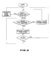
- Fig. 2 is a flowchart which summarily illustrates a manner of performing the aforementioned controlling operation in relation to the hold processing of the automatic speed changing apparatus (particularly, the controller 30), i.e., a processing to be performed when the select lever 11 is actuated to the "HOLD" position.
- the hold processing is executed under conditions that speed changing is controlled unless the select lever 11 is actuated to the "HOLD" position and the select lever 11 is actuated by no means in the direction of the arrow mark F2 once it has been actuated to the "HOLD" position.
- the hold processing permits the current speed stage of the transmission 60 (which has been selected at this time point) to be maintained, as mentioned above.
- the automatic speed changing apparatus assures that movement of the vehicle can excellently be stabilized by virtue of the hold function provided in that way and moreover fatigue of a driver (operator) can be minimized
- the automatic speed changing apparatus is very significant for a passenger car, a truck or the like vehicle of which movement is comparatively few shifted from forward movement to rearward movement and vice versa but employment of the automatic speed changing apparatus is still problematical for a construction machine such as a wheel loader or the like which is designed and constructed in the form of a vehicle having tires used therefor in the same manner as the aforementioned vehicles.
- the present invention has been made with the foregoing background in mind and its object resides in providing an automatic speed changing apparatus for a vehicle in the form of a construction machine such as a wheel loader or the like which assures that a hold processing can always be executed at a high efficiency while a load to be carried by an operator (driver) is reduced.
- switch means i.e., a hold switch for making a designation as to whether a hold processing should be executed or not is provided for a controller of the automatic speed changing apparatus independently of actuation levers in the form of a select lever or the like so that the controller executes a hold processing, i.e., a processing of automatically holding a gear position (speed stage) in the transmission which has been selected at this time point.
- a hold processing i.e., a processing of automatically holding a gear position (speed stage) in the transmission which has been selected at this time point.
- the transmission is once forcibly shifted to a second speed stage (representative of a shift change), and thereafter when movement of the vehicle reaches the required speed stage which has been held as the vehicle speed is increased, the hold processing is executed so as to automatically hold this speed stage.
- Fig. 1 is a view schematically illustrating by way of system diagram a conventional automatic speed changing apparatus employable for a vehicle
- Fig. 2 is a flowchart illustrating performing a plurality of processings, particularly a hold processing using the automatic speed changing apparatus shown in Fig. 1
- Fig. 3 is a perspective view illustrating an actuating section and a section to be controlled in the automatic speed changing apparatus for a vehicle in accordance with an embodiment of the present invention
- Fig. 4 is a view schematically illustrating a manner of arranging a variety of sensors in case where the automatic speed changing apparatus is employed for a wheel loader
- Fig. 1 is a view schematically illustrating by way of system diagram a conventional automatic speed changing apparatus employable for a vehicle
- Fig. 2 is a flowchart illustrating performing a plurality of processings, particularly a hold processing using the automatic speed changing apparatus shown in Fig. 1
- Fig. 3 is a perspective view illustrating an actuating section and a section to be controlled in
- FIG. 5 is a block diagram illustrating by way of example the electrical structure of portions relating mainly to a hold processing to be performed by the automatic speed changing apparatus
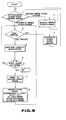
- Fig. 6 is a flowchart illustrating a manner of performing mainly a hold processing ("hold" mode processing") in the automatic speed changing apparatus
- Fig. 7 is a view schematically illustrating an automatic speed changing apparatus in accordance with other embodiment of the present invention in case where the present invention is applied to the conventional apparatus (system) as shown in Fig. 1.
- Fig. 3 is a perspective view which schematically illustrates the structure of a driver seat section and objects to be controlled in a wheel loader, i.e., a transmission section to be controlled by the automatic speed changing apparatus of the present invention.
- numeral 101 designates a steering handle
- reference numeral 110 does a lever device
- reference numeral 111 does a forward/rearward shifting lever arranged on the lever device 110 to perform a shifting operation of shifting from F (forward movement) to R (rearward movement) of a vehicle and vice versa as reprsented by arrow marks in the drawing
- reference numeral 112 does a speed stage shifting lever likewise arranged on the lever device 110 to perform a shifting operation of shifting to a required speed stage for the vehicle as represented by arrow marks in the drawing
- reference numeral 113 does an automatic speed changing/manual speed changing shifting lever provided at the fore end of the speed stage shifting lever 112 to perform a shifting operation from an "automatic speed changing" mode to a "manual speed changing” mode
- reference numeral 161 designates a solenoid valve mounted on the transmission 160 to shift the gear position (speed stage) in the transmission 160.
- the forward movement/rearward movement shifting lever 111 is provided with a sensor 111S for detecting the current shifted position and the speed stage shifting lever 112 is provided with a sensor 112S for detecting the current shifted position (in practice, these sensors 1115 and 112S being incorporated in the lever device 110), although they are not shown in F ig. 3.
- the speed stage shifting lever 112 is used for both modes, I.e., "automatic speed changing" mode and "manual speed changing" mode, and in case where the speed stage shifting lever 112 is actuated to, e.g., a position "3", an automatic speed changing operation can be performed within the range comprising a first speed stage, a second speed state and a third speed stage depending upon a quantity of depressing operation of the acceleration pedal 120, while in case where the speed stage shifting lever 112 is actuated to, e.g., a position "2", an automatic speed changing operation can be performed within the range comprising a first speed stage and a second speed stage depending upon a quantity of depressing operation of the acceleration pedal 120.
- the range in which an automatic speed changing operation is performed can be set in the same manner in conformity with the aforementioned rule.
- Fig. 4 schematically illustrates how essential components inclusive these various sensors and switches constituting the automatic speed changing apparatus are arranged in the wheel loader and how they are operatively associated with each other.
- reference numeral 130 designates a controller
- reference numeral 137 does a solenoid valve driving circuit to be controlled by the controller 130
- reference numeral 140 does an engine
- reference numeral 142 does an engine speed detecting sensor for detecting the current engine speed
- reference numeral 150 does a clutch
- reference numeral 162 does a vehicle speed detecting sensor for detecting the current speed of movement of the wheel loader.
- Other components and units have been already described above.
- Fig. 5 illustrates a structure of the automatic speed changing apparatus by showing how the aforementioned components and units are electrically connected to each other and Fig. 6 illustrates by way of flowchart a manner of performing operations in connection with the aforementioned hold mode processing. Structure and operations of the automatic speed changing apparatus will be described below with reference to Figs. 5 and 6.
- Informations on detected positions derived from the forward movement/rearward movement shifting lever position detecting sensor 111S, the speed stage shifting lever position detecting sensor 112S and the acceleration pedal position detecting sensor 120S are converted into digital signals by A/D (analogue/digital) converters 191, 192 and 193 so that they are inputted into the controller (computor) 130.
- A/D analogue/digital converters 191, 192 and 193 so that they are inputted into the controller (computor) 130.
- the content of actuations of the automatic speed changing/manual speed changing shifting switches 113 and the hold switch 180 is likewise inputted into the controller 130 in the form of a binary signal.
- the controller 130 is operated such that these inputted signals are introduced into an arithmetic circuit (CPU) 133 via a first input interface 131.
- CPU arithmetic circuit
- detected informations derived from the vehicle speed detecting sensor 162 and the engine speed detecting sensor 142 are converted into digital signals by A/D converters 194 and 195 so that they are inputted into the controller. 130.
- the controller 130 is operated such that these inputted signals are introduced into the arithmetic circuit 133 via a second input interface 132.
- the arithmetic circuit (CPU) 133 is a circuit in which a variety of signals inputted via the input interfaces 131 and 132 in accordance with a processing program previously stored in a program memory 134 are processed as required and the solenoid valve driving circuit 137 for driving the transmission shift solenoid 161, an electronic governor (not shown) for controlling a rotational speed of the engine 140, a solenoid valve (not shown) for turning on and off the clutch 150 and other associated components are controlled so as to match the content of actuations of the levers 111 and 112, the pedal 120 and the switches 113 and 180 executed by an operator. Control signals outputted from the arithmetic circuit 133 are transmitted via an output interface 135 to respective circuit to be controlled.
- a hold data memory 136 incorporated in the controller 133 is a memory in which when the hold switch 180 is shifted to an ON side, control data to be given to the solenoid valve driving circuit 137 from the arithmetic circuit 133 at this time point, i.e., a speed stage command to be issued at this time point is stored. While the hold switch 180 is shifted to the ON side in that way, the subsequent controlling and processing are executed in the arithmetic circuit 133 in accordance with the manner as represented by a step 5 and subsequent steps in a flowchart shown in Fig. 6.
- the arithmetic calculating circuit 133 makes a determination that the automatic speed changing has been designated (step 1 in Fig. 6) so that controlling and processing are executed in accordance with a hitherto known "manual speed changing" mode in response to detection of an actuation position of the speed stage shifting lever 112 (step 2 in Fig. 6).
- the hold switch 180 is shifted to the OFF side while the switch 113 is shifted to the ON side to designate "automatic speed change" (step 1 in Fig.
- the arithmetic circuit 133 makes a determination that the hold switch 180 has been shifted to the OFF side (step 3 in Fig. 6), controlling and processing are executed in accordance with "automatic speed changing" mode on the basis of the automatic speed change range designated and set by the speed stage shifting lever 112 in the above-described manner in response to detection of a depressing position of the acceleration pedal 120 (step 4 in Fig. 6).
- the arithmetic circuit 133 stores in the hold data memory 136 control data (speed stage command) to be given to the solenoid valve driving circuit 137 at this time point and then controls the solenoid valve driving circuit 137 in conformity with control data to be later stored in the hold data memory 136.
- This permits a speed stage selected in accordance with the current mode, i.e., "automatic speed changing" mode at this time point to be maintained in the transmission 160 (step 5 in Fig. 6).
- the arithmetic circuit 133 makes a determination that the forward movement/rearward movement has been shifted in that way (step 6 in Fig. 6). Then, when the vehicle starts its movement (either of forward movement and rearward movement), the transmission shifting solenoid valve 161 is first controlled via the solenoid valve driving circuit 137 so that the transmission 160 is forcibly shifted and changed to a second stage (step 7 in Fig. 6).
- controlling is executed for acceleration and selection of speed stage in accordance with "automatic speed changing" mode in correspondence to an extent of depressing of the acceleration pedal 120 until a control command value to be given to the solenoid valve driving circuit 137 reaches the command value (control data) stored in the hold data memory 136 (step 8 in Fig. 6).
- the arithmetic circuit 133 makes a determination that the control command value has reached the command value stored in the hold data memory 135 and thereafter the program automatically goes to the processing at the step 5, i.e., a processing of controlling the solenoid valve driving circuit 137 in accordance with the control data (control command value) stored in the hold data memory 136.
- Such processing to be executed by the arithmetic circuit 133 continues until the hold switch 180 is disconnected, i.e., until the hold switch 180 is shifted to the OFF side.
- a hold processing is brought in such a sate that it automatically continues in response to actuation of the hold switch 180. Thereafter, speed of the vehicle is automatically changed to the movement speed at a required speed stage which has been held in that way, when movement of the vehicle is shifted from forward movement to rearward movement and vice versa. Consequently, with the automatic speed changing apparatus of the present invention, any operation can be performed at a high efficiency with an operator's load reduced remarkably using a vehicle such as the illustrated wheel loader or the like of which movement is often shifted from forward movement to rearward movement and vice versa.
- shift control (shift change) is once forcibly carried out to a second speed stage, when the current speed stage is automatically shifted to a required speed stage which has been held in that way, i.e. when the vehicle starts its movement in accordance with the "hold" mode irrespective of forward movement or rearward movement.
- the speed stage reaches a required speed stage which has been held in that way as the vehicle speed is increased, the speed stage is automatically maintained at the above required speed stage by executing the hold processing. Consequently, when vehicle movement is attained at the required speed stage after the vehicle movement is shifted from forward movement to rearward movement and vice versa, shifting to the required speed stage can always be performed stably and smoothly.
- detection is made by the acceleration pedal position detecting sensor 120S as to whether the vehicle is held at the moving state or not but such detection can practically be made by monitoring the rotational speed of the engine 140.
- the automatic speed changing apparatus may be constructed with the acceleration pedal position detecting sensor 120S and the A/D converter 193 removed therefrom.
- a select lever device 10' is a device adapted to issue a command as to one of "R (rearward movement)", “N (neutral)” and “D (forward movement)” as well as “automatic speed changing” mode or “manual speed changing” mode in the same manner as the select lever device 10 in Fig. 1, when the vehicle starts its movement.
- a difference point from the select lever device 10 shown in Fig. 1 consists in that the select lever device 10' does not have a function of commanding a hold processing as mentioned above.
- a command as to whether a hold processing is required or not is issued in response to actuation of a hold switch 180 arranged separately.
- the select lever device 10' it is assumed that only a command for the "manual speed changing" mode is issued, when a select lever 11 is shifted to a "MANU" position (representing a manual position).
- reference numeral 170 designates a working machine actuating lever as described hereinbefore.
- the working machine actuating lever 170 is removed from the automatic speed changing apparatus in case where the vehicle is a passenger car, a truck or the like.
- a controller 30' has functions equal to those of the controller 30 according to the preceding embodiment shown in Fig. 5 so that when a "hold" mode is designated via the hold switch 180, a step 6 and subsequent steps as shown in Fig. 6 which represents a flowchart are repeatedly executed in the same manner as in the preceding embodiment.
- an operation can be performed at a high efficiency with an operator's load remarkably reduced using a vehicle such as a wheel loader or the like of which movement is often shifted from forward movement to rearward movement and vice versa.
- a vehicle such as a wheel loader or the like of which movement is often shifted from forward movement to rearward movement and vice versa.
- a position where the hold switch 180 is located and a manner of arranging the hold switch 180 can be determined arbitrarily. Provided that the position and the manner are determined such that the hold switch 180 can be actuated independently of other actuating levers, the hold switch 180 may be arranged at any position in accordance with any manner.
- the computor may, of course, be constructed in the form of a so-called hardware circuit so that the same controlling operations for automatic speed changing as mentioned above are executed using the hardware circuit.
- movement of a vehicle can immediately be achieved in any case in an automatic manner at a required speed stage which has been previously determined.
- a work can be performed at a high efficiency using a construction machine such as a wheel loader or the like of which movement is repeatedly shifted from forward movement to rearward movement and vice versa.
Landscapes
- Engineering & Computer Science (AREA)
- Mechanical Engineering (AREA)
- General Engineering & Computer Science (AREA)
- Chemical & Material Sciences (AREA)
- Combustion & Propulsion (AREA)
- Transportation (AREA)
- Automation & Control Theory (AREA)
- Control Of Transmission Device (AREA)
- Arrangement Or Mounting Of Control Devices For Change-Speed Gearing (AREA)
- Operation Control Of Excavators (AREA)
- Gear-Shifting Mechanisms (AREA)
Abstract
Applications Claiming Priority (2)
| Application Number | Priority Date | Filing Date | Title |
|---|---|---|---|
| JP1988009543U JPH0650258Y2 (ja) | 1988-01-29 | 1988-01-29 | 車両の自動変速装置 |
| JP9543/88U | 1988-01-29 |
Publications (3)
| Publication Number | Publication Date |
|---|---|
| EP0353310A1 true EP0353310A1 (fr) | 1990-02-07 |
| EP0353310A4 EP0353310A4 (en) | 1991-08-14 |
| EP0353310B1 EP0353310B1 (fr) | 1994-03-30 |
Family
ID=11723188
Family Applications (1)
| Application Number | Title | Priority Date | Filing Date |
|---|---|---|---|
| EP89901743A Expired - Lifetime EP0353310B1 (fr) | 1988-01-29 | 1989-01-27 | Transmission automatique pour vehicules |
Country Status (7)
| Country | Link |
|---|---|
| US (1) | US5050456A (fr) |
| EP (1) | EP0353310B1 (fr) |
| JP (1) | JPH0650258Y2 (fr) |
| KR (1) | KR960014071B1 (fr) |
| AU (1) | AU609938B2 (fr) |
| DE (1) | DE68914209T2 (fr) |
| WO (1) | WO1989007057A1 (fr) |
Cited By (19)
| Publication number | Priority date | Publication date | Assignee | Title |
|---|---|---|---|---|
| EP0444250A1 (fr) * | 1990-02-22 | 1991-09-04 | Dr.Ing.h.c. F. Porsche Aktiengesellschaft | Dispositif de changement de vitesse pour transmission automatique |
| EP0444676A1 (fr) * | 1990-03-01 | 1991-09-04 | Mazda Motor Corporation | Serveur pour une transmission automatique de véhicule |
| DE4119076A1 (de) * | 1990-06-08 | 1991-12-12 | Jatco Corp | Verfahren und einrichtung zur schaltsteuerung eines automatischen getriebes |
| EP0467773A1 (fr) * | 1990-07-17 | 1992-01-22 | Regie Nationale Des Usines Renault S.A. | Dispositif de commande manuelle de boîte de vitesses automatique |
| WO1992013215A1 (fr) * | 1991-01-22 | 1992-08-06 | Zf Friedrichshafen Ag | Dispositif de commutation et de selection de rapports de transmission pour une boite de vitesses a engrenages semi- ou entierement automatique d'un vehicule automobile |
| GB2256683A (en) * | 1991-06-15 | 1992-12-16 | Gen Motors France | Transmission control module using incremental manual shift mounted on steering wheel or column |
| EP0547598A1 (fr) * | 1991-12-19 | 1993-06-23 | Mitsubishi Jukogyo Kabushiki Kaisha | Transmission automatique à commande électronique pour véhicules |
| LT3373B (en) | 1991-01-04 | 1995-08-25 | Hoechst Ag | Azole derivatives, process for preparing and using thereof |
| EP0681120A1 (fr) * | 1994-05-05 | 1995-11-08 | Eaton Corporation | Régulation du verrouillage de la marche arrière |
| EP0709598A3 (fr) * | 1989-12-01 | 1997-11-12 | New Holland U.K. Limited | Caractéristique prioritaire de sélection de rapports dans un transmission à changement de rapports sous charge |
| EP0716250A3 (fr) * | 1991-06-03 | 1997-12-10 | New Holland U.K. Limited | Système de réglage d'une transmission avec logique pour empêcher des faux changements de vitesse lors d'un changement d'intention du conducteur |
| EP0784766A4 (fr) * | 1995-07-24 | 1998-05-13 | Chrysler Corp | Mecanisme de commande de changement de vitesse permettant de commander manuellement une boite automatique |
| EP0778429A3 (fr) * | 1995-12-07 | 1998-06-03 | Eaton Corporation | Système de commande pour système de transmission mécanique automatisée |
| US5861803A (en) * | 1995-07-28 | 1999-01-19 | Chrysler Corporation | Method of displaying a shift lever position for electronically-controlled automatic transmission |
| EP0922887A1 (fr) * | 1997-12-11 | 1999-06-16 | Volkswagen Aktiengesellschaft | Procédé et dispositif de commande d'une transmission automatique ou d'une boíte de vitesses mécanique robotisée d'un véhicule automobile |
| US5916292A (en) * | 1995-06-28 | 1999-06-29 | Chrysler Corporation | Method of shifting in a manual mode of an electronically-controlled automatic transmission system |
| GB2345945A (en) * | 1998-12-23 | 2000-07-26 | Agco Limited | Power shuttle gearbox with cycle time adjustment of clutch packs |
| WO2001023787A1 (fr) * | 1999-09-29 | 2001-04-05 | Zf Friedrichshafen Ag | Systeme pour indiquer a l'avance un changement de vitesse automatique imminent |
| WO2009015980A3 (fr) * | 2007-07-27 | 2009-05-07 | Zahnradfabrik Friedrichshafen | Procédé de commande d'une boîte de vitesses automatique ou automatisée d'un véhicule à moteur |
Families Citing this family (17)
| Publication number | Priority date | Publication date | Assignee | Title |
|---|---|---|---|---|
| US5467854A (en) * | 1994-06-07 | 1995-11-21 | Caterpillar Inc. | Method of controlling clutch-to-clutch shifts for a powershift transmission |
| US5520593A (en) * | 1994-07-15 | 1996-05-28 | Caterpillar Inc. | Transmission shift control and shift prevention during an inching operation |
| US5505100A (en) * | 1994-09-29 | 1996-04-09 | Caterpillar Inc. | Method of controlling interrupted shifts for a powershift transmission |
| US5551930A (en) * | 1995-04-13 | 1996-09-03 | Caterpillar Inc. | Adaptive control method for an automatic transmission |
| US5580332A (en) * | 1995-04-13 | 1996-12-03 | Caterpillar Inc. | Method for determining the fill time of a transmission clutch |
| US6115661A (en) * | 1998-04-09 | 2000-09-05 | Caterpillar Inc. | End-of-fill detector for a fluid actuated clutch |
| US5950789A (en) * | 1998-04-27 | 1999-09-14 | Caterpillar Inc. | End of fill detector for a fluid actuated clutch |
| US6030315A (en) * | 1998-10-27 | 2000-02-29 | Cumiins Engine Company, Inc. | System for overriding hold mode operation of an automated transmission |
| DE19963782B4 (de) * | 1999-12-30 | 2008-11-20 | Robert Bosch Gmbh | Steuerung für ein Fahrzeug mit einer Getriebesteuerung |
| DE102004057724A1 (de) * | 2004-11-30 | 2006-06-01 | Bayerische Motoren Werke Ag | Vorrichtung zum Steuern eines automatisch schaltenden Getriebes |
| CN101529130B (zh) * | 2006-11-30 | 2013-02-06 | 日立建机株式会社 | 工业车辆的变速控制装置 |
| US8224540B2 (en) * | 2009-12-14 | 2012-07-17 | Cnh America Llc | Apparatus and method for inching using a continuously variable transmission |
| BR112015003486B1 (pt) | 2012-08-16 | 2022-02-22 | Cnh America Llc | Veículo agrícola e método de operar um veículo de trabalho |
| JP5840104B2 (ja) * | 2012-10-19 | 2016-01-06 | 日立建機株式会社 | 作業車両の走行制御装置 |
| US12338606B2 (en) * | 2021-09-02 | 2025-06-24 | Caterpillar Inc. | Inching systems and methods |
| US12385222B2 (en) | 2022-08-17 | 2025-08-12 | Caterpillar Inc. | Powertrain eco-mode for work machines |
| EP4656910A1 (fr) * | 2024-05-28 | 2025-12-03 | Volvo Truck Corporation | Dispositif de commande pour la sélection de vitesse dans un véhicule à propulsion électrique et procédé de commande de sélection de vitesse dans un véhicule à propulsion électrique |
Family Cites Families (20)
| Publication number | Priority date | Publication date | Assignee | Title |
|---|---|---|---|---|
| US4208925A (en) * | 1977-08-11 | 1980-06-24 | Caterpillar Tractor Co. | Electronic transmission control and method therefor |
| AU525952B2 (en) * | 1978-01-24 | 1982-12-09 | Lahive, John A. | Mechanical automatic transmission |
| DE2918856A1 (de) * | 1978-07-01 | 1980-11-13 | Kaspar Ing Grad Franz | Sowohl von hand, als auch automatisch betaetigbare schaltvorrichtung fuer zahnraederwechselgetriebe von kraftfahrzeugen |
| SE417413B (sv) * | 1979-06-28 | 1981-03-16 | Volvo Bm | Sett att styra en kraftoverforingsanordning samt anordning for utforande av settet |
| US4414863A (en) * | 1980-02-19 | 1983-11-15 | Deere & Company | Automatic electronic control for a power shift transmission |
| US4425620A (en) * | 1981-01-28 | 1984-01-10 | Steiger Tractor, Inc. | Electrical control for power shift transmission |
| US4608873A (en) * | 1983-04-27 | 1986-09-02 | Clark Equipment Company | Elective automatic shift transmission |
| GB8418749D0 (en) * | 1984-07-23 | 1984-08-30 | Eaton Ltd | Semi-automatic transmission control |
| FI72789C (fi) * | 1984-10-24 | 1987-07-10 | Konejukka Oy | Halvautomatiskt vaexelsystem. |
| JPS61103044A (ja) * | 1984-10-26 | 1986-05-21 | Toyoda Autom Loom Works Ltd | 自動変速機 |
| DE3608208A1 (de) * | 1985-03-23 | 1986-09-25 | Zahnradfabrik Friedrichshafen Ag, 7990 Friedrichshafen | Steuereinrichtung zum schalten von stufenwechselgetrieben |
| JPH0658134B2 (ja) * | 1985-10-31 | 1994-08-03 | マツダ株式会社 | 自動変速機の制御装置 |
| US4711141A (en) * | 1986-04-30 | 1987-12-08 | Eaton Corporation | Method for controlling AMT system including after transmission gear change clutch and fuel control |
| JP2727183B2 (ja) * | 1987-03-04 | 1998-03-11 | 富士重工業 株式会社 | 自動変速機の変速制御装置 |
| JPS63275843A (ja) * | 1987-05-02 | 1988-11-14 | Daikin Mfg Co Ltd | 変速段切り換え制御装置 |
| HU198778B (en) * | 1987-10-14 | 1989-11-28 | Csepeli Autogyar | Method for starting motor vehicle by back-and-forth running |
| US4916979A (en) * | 1988-04-18 | 1990-04-17 | Eaton Corporation | On-grade shift logic with provision for skip downshifts |
| US4852006A (en) * | 1988-04-18 | 1989-07-25 | Eaton Corporation | Amt off-highway downshift logic |
| US4916983A (en) * | 1988-11-07 | 1990-04-17 | The United States Of America As Represented By The Secretary Of The Army | Override control for vehicle drive train |
| JPH06141628A (ja) * | 1992-11-05 | 1994-05-24 | Kubota Corp | 芝張り機の土供給装置 |
-
1988
- 1988-01-29 JP JP1988009543U patent/JPH0650258Y2/ja not_active Expired - Lifetime
-
1989
- 1989-01-27 WO PCT/JP1989/000079 patent/WO1989007057A1/fr not_active Ceased
- 1989-01-27 DE DE68914209T patent/DE68914209T2/de not_active Expired - Lifetime
- 1989-01-27 US US07/415,340 patent/US5050456A/en not_active Expired - Lifetime
- 1989-01-27 EP EP89901743A patent/EP0353310B1/fr not_active Expired - Lifetime
- 1989-01-27 AU AU29394/89A patent/AU609938B2/en not_active Ceased
- 1989-01-27 KR KR1019890701768A patent/KR960014071B1/ko not_active Expired - Fee Related
Cited By (31)
| Publication number | Priority date | Publication date | Assignee | Title |
|---|---|---|---|---|
| EP0709598A3 (fr) * | 1989-12-01 | 1997-11-12 | New Holland U.K. Limited | Caractéristique prioritaire de sélection de rapports dans un transmission à changement de rapports sous charge |
| US5197344A (en) * | 1990-02-22 | 1993-03-30 | Dr. Ing. H.C.F. Porsche Aktiengesellschaft | Shifting arrangement for an automatic transmission |
| EP0444250A1 (fr) * | 1990-02-22 | 1991-09-04 | Dr.Ing.h.c. F. Porsche Aktiengesellschaft | Dispositif de changement de vitesse pour transmission automatique |
| EP0444676A1 (fr) * | 1990-03-01 | 1991-09-04 | Mazda Motor Corporation | Serveur pour une transmission automatique de véhicule |
| DE4119076A1 (de) * | 1990-06-08 | 1991-12-12 | Jatco Corp | Verfahren und einrichtung zur schaltsteuerung eines automatischen getriebes |
| EP0467773A1 (fr) * | 1990-07-17 | 1992-01-22 | Regie Nationale Des Usines Renault S.A. | Dispositif de commande manuelle de boîte de vitesses automatique |
| FR2664959A1 (fr) * | 1990-07-17 | 1992-01-24 | Renault | Dispositif de commande manuelle de boite de vitesses automatique. |
| LT3373B (en) | 1991-01-04 | 1995-08-25 | Hoechst Ag | Azole derivatives, process for preparing and using thereof |
| US5419412A (en) * | 1991-01-22 | 1995-05-30 | Zahnradfabrik Friedrichshafen Ag | Gear-shift control and gear-range selector for a semi-automatic or fully-automatic motion vehicle gearbox |
| WO1992013215A1 (fr) * | 1991-01-22 | 1992-08-06 | Zf Friedrichshafen Ag | Dispositif de commutation et de selection de rapports de transmission pour une boite de vitesses a engrenages semi- ou entierement automatique d'un vehicule automobile |
| EP0716250A3 (fr) * | 1991-06-03 | 1997-12-10 | New Holland U.K. Limited | Système de réglage d'une transmission avec logique pour empêcher des faux changements de vitesse lors d'un changement d'intention du conducteur |
| GB2256683B (en) * | 1991-06-15 | 1994-05-25 | Gen Motors France | Transmission control module |
| GB2256683A (en) * | 1991-06-15 | 1992-12-16 | Gen Motors France | Transmission control module using incremental manual shift mounted on steering wheel or column |
| US5351570A (en) * | 1991-12-19 | 1994-10-04 | Mitsubishi Jukogyo Kabushiki Kaisha | Electronically controlled automatic transmission for vehicles |
| EP0547598A1 (fr) * | 1991-12-19 | 1993-06-23 | Mitsubishi Jukogyo Kabushiki Kaisha | Transmission automatique à commande électronique pour véhicules |
| EP0681120A1 (fr) * | 1994-05-05 | 1995-11-08 | Eaton Corporation | Régulation du verrouillage de la marche arrière |
| US5913935A (en) * | 1994-06-02 | 1999-06-22 | Chrysler Corporation | Shift control mechanism to manually shift an automatic transmission |
| US5916292A (en) * | 1995-06-28 | 1999-06-29 | Chrysler Corporation | Method of shifting in a manual mode of an electronically-controlled automatic transmission system |
| EP0784766A4 (fr) * | 1995-07-24 | 1998-05-13 | Chrysler Corp | Mecanisme de commande de changement de vitesse permettant de commander manuellement une boite automatique |
| US5861803A (en) * | 1995-07-28 | 1999-01-19 | Chrysler Corporation | Method of displaying a shift lever position for electronically-controlled automatic transmission |
| US5943912A (en) * | 1995-12-07 | 1999-08-31 | Eaton Corporation | Control for automated mechanical transmission system |
| EP0778429A3 (fr) * | 1995-12-07 | 1998-06-03 | Eaton Corporation | Système de commande pour système de transmission mécanique automatisée |
| EP0922887A1 (fr) * | 1997-12-11 | 1999-06-16 | Volkswagen Aktiengesellschaft | Procédé et dispositif de commande d'une transmission automatique ou d'une boíte de vitesses mécanique robotisée d'un véhicule automobile |
| GB2345945B (en) * | 1998-12-23 | 2003-03-19 | Aggo Ltd | Control system for a power shuttle gearbox |
| GB2345945A (en) * | 1998-12-23 | 2000-07-26 | Agco Limited | Power shuttle gearbox with cycle time adjustment of clutch packs |
| WO2001023787A1 (fr) * | 1999-09-29 | 2001-04-05 | Zf Friedrichshafen Ag | Systeme pour indiquer a l'avance un changement de vitesse automatique imminent |
| US6774780B1 (en) | 1999-09-29 | 2004-08-10 | Zf Friedrichshafen Ag | Device for the advance indication of an automatically executed shift |
| WO2009015980A3 (fr) * | 2007-07-27 | 2009-05-07 | Zahnradfabrik Friedrichshafen | Procédé de commande d'une boîte de vitesses automatique ou automatisée d'un véhicule à moteur |
| US8512205B2 (en) | 2007-07-27 | 2013-08-20 | Zf Friedrichshafen Ag | Method for controlling an automatic transmission of a motor vehicle |
| US8715137B2 (en) | 2007-07-27 | 2014-05-06 | Zf Friedrichshafen Ag | Method for controlling an automatic transmission of a motor vehicle |
| EP2171316B1 (fr) * | 2007-07-27 | 2014-11-05 | ZF Friedrichshafen AG | Procédé de commande d'une boîte de vitesses automatique ou automatisée d'un véhicule à moteur |
Also Published As
| Publication number | Publication date |
|---|---|
| DE68914209T2 (de) | 1994-07-07 |
| JPH01114324U (fr) | 1989-08-01 |
| EP0353310B1 (fr) | 1994-03-30 |
| AU609938B2 (en) | 1991-05-09 |
| EP0353310A4 (en) | 1991-08-14 |
| WO1989007057A1 (fr) | 1989-08-10 |
| KR960014071B1 (ko) | 1996-10-12 |
| KR900700315A (ko) | 1990-08-13 |
| DE68914209D1 (de) | 1994-05-05 |
| US5050456A (en) | 1991-09-24 |
| AU2939489A (en) | 1989-08-25 |
| JPH0650258Y2 (ja) | 1994-12-21 |
Similar Documents
| Publication | Publication Date | Title |
|---|---|---|
| US5050456A (en) | Automatic speed changing apparatus for vehicle | |
| JPH1148823A (ja) | 車両用定速走行装置 | |
| EP1103742B1 (fr) | Système de sélection de mode pour transmission automatique programmable par le conducteur | |
| CN1131796C (zh) | 自定义起动速比选择的控制系统/方法 | |
| EP0911207B1 (fr) | Commande de changement de vitesses pour freinage moteur optimal | |
| EP0769640B1 (fr) | Système et méthode de sélection d'un sauté de vitesses | |
| EP0270674B1 (fr) | Transmission automatique d'un chargeur a roue | |
| EP0369008B1 (fr) | Transmission automatique pour chargeuse a roues | |
| US11879544B2 (en) | Method for avoiding activation of a sailing functionality, a transmission system and a vehicle comprising a transmission system | |
| JP2008530469A (ja) | 自動車における自動変速機の制御装置及び制御方法 | |
| JPS63265730A (ja) | ホイ−ルロ−ダの自動変速装置 | |
| KR920000692B1 (ko) | 차량용 자동변속장치 | |
| JPH1151179A (ja) | 車両用定速走行装置 | |
| JPH07305764A (ja) | 動力車両の変速装置 | |
| JPS6127346A (ja) | 自動変速機付き産業車両におけるインチング制御装置 | |
| JPH09203457A (ja) | 自動変速機の変速制御装置 | |
| JP3216517B2 (ja) | 変速機の変速操作装置 | |
| JPH0790726B2 (ja) | 定速走行装置付車両に搭載した自動変速機の変速制御装置 | |
| JPS61244954A (ja) | 建設機械の変速機キツクダウン装置 | |
| JP3320920B2 (ja) | 坂道発進補助装置 | |
| JP2948447B2 (ja) | 半自動変速機 | |
| JPH0295936A (ja) | 自動変速機付き産業車両におけるスイッチバック走行制御装置 | |
| GB2356676A (en) | Driver programmable transmission mode selection for automatic transmission | |
| JPH05229365A (ja) | 自動変速機の変速制御装置 | |
| JPS5919752A (ja) | 車両用自動変速機 |
Legal Events
| Date | Code | Title | Description |
|---|---|---|---|
| PUAI | Public reference made under article 153(3) epc to a published international application that has entered the european phase |
Free format text: ORIGINAL CODE: 0009012 |
|
| 17P | Request for examination filed |
Effective date: 19890915 |
|
| AK | Designated contracting states |
Kind code of ref document: A1 Designated state(s): DE FR GB SE |
|
| A4 | Supplementary search report drawn up and despatched |
Effective date: 19910621 |
|
| AK | Designated contracting states |
Kind code of ref document: A4 Designated state(s): DE FR GB SE |
|
| 17Q | First examination report despatched |
Effective date: 19920909 |
|
| GRAA | (expected) grant |
Free format text: ORIGINAL CODE: 0009210 |
|
| AK | Designated contracting states |
Kind code of ref document: B1 Designated state(s): DE FR GB SE |
|
| PG25 | Lapsed in a contracting state [announced via postgrant information from national office to epo] |
Ref country code: FR Effective date: 19940330 |
|
| REF | Corresponds to: |
Ref document number: 68914209 Country of ref document: DE Date of ref document: 19940505 |
|
| EN | Fr: translation not filed | ||
| PG25 | Lapsed in a contracting state [announced via postgrant information from national office to epo] |
Ref country code: GB Effective date: 19950127 |
|
| EAL | Se: european patent in force in sweden |
Ref document number: 89901743.8 |
|
| PLBE | No opposition filed within time limit |
Free format text: ORIGINAL CODE: 0009261 |
|
| STAA | Information on the status of an ep patent application or granted ep patent |
Free format text: STATUS: NO OPPOSITION FILED WITHIN TIME LIMIT |
|
| 26N | No opposition filed | ||
| GBPC | Gb: european patent ceased through non-payment of renewal fee |
Effective date: 19950127 |
|
| PGFP | Annual fee paid to national office [announced via postgrant information from national office to epo] |
Ref country code: SE Payment date: 19980116 Year of fee payment: 10 |
|
| PG25 | Lapsed in a contracting state [announced via postgrant information from national office to epo] |
Ref country code: SE Free format text: LAPSE BECAUSE OF NON-PAYMENT OF DUE FEES Effective date: 19990128 |
|
| PGFP | Annual fee paid to national office [announced via postgrant information from national office to epo] |
Ref country code: DE Payment date: 20080124 Year of fee payment: 20 |