EP0353733B1 - Brennstoffanordnung für einen Kernreaktor, Verfahren zu deren Herstellung und Strukturteil dafür - Google Patents
Brennstoffanordnung für einen Kernreaktor, Verfahren zu deren Herstellung und Strukturteil dafür Download PDFInfo
- Publication number
- EP0353733B1 EP0353733B1 EP89114266A EP89114266A EP0353733B1 EP 0353733 B1 EP0353733 B1 EP 0353733B1 EP 89114266 A EP89114266 A EP 89114266A EP 89114266 A EP89114266 A EP 89114266A EP 0353733 B1 EP0353733 B1 EP 0353733B1
- Authority
- EP
- European Patent Office
- Prior art keywords
- surface layer
- nuclear reactor
- structural member
- alloy
- intermediate layer
- Prior art date
- Legal status (The legal status is an assumption and is not a legal conclusion. Google has not performed a legal analysis and makes no representation as to the accuracy of the status listed.)
- Expired - Lifetime
Links
- 239000000446 fuel Substances 0.000 title claims description 62
- 238000004519 manufacturing process Methods 0.000 title description 8
- 229910045601 alloy Inorganic materials 0.000 claims description 89
- 239000000956 alloy Substances 0.000 claims description 89
- 239000010410 layer Substances 0.000 claims description 57
- 239000002344 surface layer Substances 0.000 claims description 39
- 239000000463 material Substances 0.000 claims description 36
- 125000006850 spacer group Chemical group 0.000 claims description 35
- 238000000034 method Methods 0.000 claims description 27
- 238000010438 heat treatment Methods 0.000 claims description 26
- 238000003466 welding Methods 0.000 claims description 26
- XLYOFNOQVPJJNP-UHFFFAOYSA-N water Substances O XLYOFNOQVPJJNP-UHFFFAOYSA-N 0.000 claims description 19
- 238000000137 annealing Methods 0.000 claims description 18
- 238000005253 cladding Methods 0.000 claims description 17
- 229910052759 nickel Inorganic materials 0.000 claims description 13
- 229910052742 iron Inorganic materials 0.000 claims description 11
- 229910052718 tin Inorganic materials 0.000 claims description 11
- 229910052750 molybdenum Inorganic materials 0.000 claims description 10
- 229910052804 chromium Inorganic materials 0.000 claims description 9
- 238000005482 strain hardening Methods 0.000 claims description 9
- 238000010791 quenching Methods 0.000 claims description 7
- 230000000171 quenching effect Effects 0.000 claims description 6
- 239000010935 stainless steel Substances 0.000 claims description 6
- 229910001220 stainless steel Inorganic materials 0.000 claims description 5
- 229910052726 zirconium Inorganic materials 0.000 claims description 4
- QCWXUUIWCKQGHC-UHFFFAOYSA-N Zirconium Chemical compound [Zr] QCWXUUIWCKQGHC-UHFFFAOYSA-N 0.000 claims description 3
- 239000012535 impurity Substances 0.000 claims 7
- 229910052758 niobium Inorganic materials 0.000 claims 5
- 229910052748 manganese Inorganic materials 0.000 claims 2
- 229910052745 lead Inorganic materials 0.000 claims 1
- 239000003758 nuclear fuel Substances 0.000 claims 1
- 229910052725 zinc Inorganic materials 0.000 claims 1
- 238000005260 corrosion Methods 0.000 description 64
- 230000007797 corrosion Effects 0.000 description 55
- UFHFLCQGNIYNRP-UHFFFAOYSA-N Hydrogen Chemical compound [H][H] UFHFLCQGNIYNRP-UHFFFAOYSA-N 0.000 description 15
- 229910052739 hydrogen Inorganic materials 0.000 description 15
- 239000001257 hydrogen Substances 0.000 description 15
- 238000010521 absorption reaction Methods 0.000 description 12
- 229910001093 Zr alloy Inorganic materials 0.000 description 11
- 229910001182 Mo alloy Inorganic materials 0.000 description 8
- 238000001816 cooling Methods 0.000 description 8
- 229910001257 Nb alloy Inorganic materials 0.000 description 6
- 238000005097 cold rolling Methods 0.000 description 6
- 230000000694 effects Effects 0.000 description 6
- PXHVJJICTQNCMI-UHFFFAOYSA-N nickel Substances [Ni] PXHVJJICTQNCMI-UHFFFAOYSA-N 0.000 description 6
- 229910018487 Ni—Cr Inorganic materials 0.000 description 5
- 230000000052 comparative effect Effects 0.000 description 5
- 239000008188 pellet Substances 0.000 description 5
- 229910000881 Cu alloy Inorganic materials 0.000 description 4
- 238000009792 diffusion process Methods 0.000 description 4
- 238000010894 electron beam technology Methods 0.000 description 4
- 238000005098 hot rolling Methods 0.000 description 4
- 239000000203 mixture Substances 0.000 description 4
- 238000009835 boiling Methods 0.000 description 2
- 230000015556 catabolic process Effects 0.000 description 2
- 238000000354 decomposition reaction Methods 0.000 description 2
- 238000006731 degradation reaction Methods 0.000 description 2
- 238000000227 grinding Methods 0.000 description 2
- 230000006698 induction Effects 0.000 description 2
- 238000002844 melting Methods 0.000 description 2
- 230000008018 melting Effects 0.000 description 2
- 238000009864 tensile test Methods 0.000 description 2
- 229910052721 tungsten Inorganic materials 0.000 description 2
- 229910000906 Bronze Inorganic materials 0.000 description 1
- RYGMFSIKBFXOCR-UHFFFAOYSA-N Copper Chemical compound [Cu] RYGMFSIKBFXOCR-UHFFFAOYSA-N 0.000 description 1
- 229910000640 Fe alloy Inorganic materials 0.000 description 1
- 229910001030 Iron–nickel alloy Inorganic materials 0.000 description 1
- 229910001128 Sn alloy Inorganic materials 0.000 description 1
- 229910008957 Sn—Mo Inorganic materials 0.000 description 1
- 229910052770 Uranium Inorganic materials 0.000 description 1
- 238000010420 art technique Methods 0.000 description 1
- 230000004888 barrier function Effects 0.000 description 1
- 239000011324 bead Substances 0.000 description 1
- SHZGCJCMOBCMKK-KGJVWPDLSA-N beta-L-fucose Chemical compound C[C@@H]1O[C@H](O)[C@@H](O)[C@H](O)[C@@H]1O SHZGCJCMOBCMKK-KGJVWPDLSA-N 0.000 description 1
- 239000010974 bronze Substances 0.000 description 1
- 238000006243 chemical reaction Methods 0.000 description 1
- 238000010276 construction Methods 0.000 description 1
- 229910052802 copper Inorganic materials 0.000 description 1
- 239000010949 copper Substances 0.000 description 1
- YOCUPQPZWBBYIX-UHFFFAOYSA-N copper nickel Chemical compound [Ni].[Cu] YOCUPQPZWBBYIX-UHFFFAOYSA-N 0.000 description 1
- KUNSUQLRTQLHQQ-UHFFFAOYSA-N copper tin Chemical compound [Cu].[Sn] KUNSUQLRTQLHQQ-UHFFFAOYSA-N 0.000 description 1
- 230000008878 coupling Effects 0.000 description 1
- 238000010168 coupling process Methods 0.000 description 1
- 238000005859 coupling reaction Methods 0.000 description 1
- 238000005336 cracking Methods 0.000 description 1
- 239000013078 crystal Substances 0.000 description 1
- 230000003247 decreasing effect Effects 0.000 description 1
- 230000001419 dependent effect Effects 0.000 description 1
- 230000002708 enhancing effect Effects 0.000 description 1
- 230000007613 environmental effect Effects 0.000 description 1
- 238000005242 forging Methods 0.000 description 1
- 230000014509 gene expression Effects 0.000 description 1
- 238000009863 impact test Methods 0.000 description 1
- 230000010354 integration Effects 0.000 description 1
- 229910052751 metal Inorganic materials 0.000 description 1
- 239000002184 metal Substances 0.000 description 1
- 230000003647 oxidation Effects 0.000 description 1
- 238000007254 oxidation reaction Methods 0.000 description 1
- OOAWCECZEHPMBX-UHFFFAOYSA-N oxygen(2-);uranium(4+) Chemical compound [O-2].[O-2].[U+4] OOAWCECZEHPMBX-UHFFFAOYSA-N 0.000 description 1
- 239000002245 particle Substances 0.000 description 1
- 230000001737 promoting effect Effects 0.000 description 1
- 238000004080 punching Methods 0.000 description 1
- 238000001953 recrystallisation Methods 0.000 description 1
- 238000005096 rolling process Methods 0.000 description 1
- VSZWPYCFIRKVQL-UHFFFAOYSA-N selanylidenegallium;selenium Chemical compound [Se].[Se]=[Ga].[Se]=[Ga] VSZWPYCFIRKVQL-UHFFFAOYSA-N 0.000 description 1
- 239000002356 single layer Substances 0.000 description 1
- 239000006104 solid solution Substances 0.000 description 1
- 229910001256 stainless steel alloy Inorganic materials 0.000 description 1
- FCTBKIHDJGHPPO-UHFFFAOYSA-N uranium dioxide Inorganic materials O=[U]=O FCTBKIHDJGHPPO-UHFFFAOYSA-N 0.000 description 1
- JFALSRSLKYAFGM-UHFFFAOYSA-N uranium(0) Chemical compound [U] JFALSRSLKYAFGM-UHFFFAOYSA-N 0.000 description 1
Images


Classifications
-
- G—PHYSICS
- G21—NUCLEAR PHYSICS; NUCLEAR ENGINEERING
- G21C—NUCLEAR REACTORS
- G21C3/00—Reactor fuel elements and their assemblies; Selection of substances for use as reactor fuel elements
- G21C3/30—Assemblies of a number of fuel elements in the form of a rigid unit
- G21C3/32—Bundles of parallel pin-, rod-, or tube-shaped fuel elements
- G21C3/34—Spacer grids
-
- G—PHYSICS
- G21—NUCLEAR PHYSICS; NUCLEAR ENGINEERING
- G21C—NUCLEAR REACTORS
- G21C3/00—Reactor fuel elements and their assemblies; Selection of substances for use as reactor fuel elements
- G21C3/02—Fuel elements
- G21C3/04—Constructional details
- G21C3/06—Casings; Jackets
- G21C3/07—Casings; Jackets characterised by their material, e.g. alloys
-
- G—PHYSICS
- G21—NUCLEAR PHYSICS; NUCLEAR ENGINEERING
- G21C—NUCLEAR REACTORS
- G21C3/00—Reactor fuel elements and their assemblies; Selection of substances for use as reactor fuel elements
- G21C3/02—Fuel elements
- G21C3/04—Constructional details
- G21C3/16—Details of the construction within the casing
- G21C3/20—Details of the construction within the casing with coating on fuel or on inside of casing; with non-active interlayer between casing and active material with multiple casings or multiple active layers
-
- Y—GENERAL TAGGING OF NEW TECHNOLOGICAL DEVELOPMENTS; GENERAL TAGGING OF CROSS-SECTIONAL TECHNOLOGIES SPANNING OVER SEVERAL SECTIONS OF THE IPC; TECHNICAL SUBJECTS COVERED BY FORMER USPC CROSS-REFERENCE ART COLLECTIONS [XRACs] AND DIGESTS
- Y02—TECHNOLOGIES OR APPLICATIONS FOR MITIGATION OR ADAPTATION AGAINST CLIMATE CHANGE
- Y02E—REDUCTION OF GREENHOUSE GAS [GHG] EMISSIONS, RELATED TO ENERGY GENERATION, TRANSMISSION OR DISTRIBUTION
- Y02E30/00—Energy generation of nuclear origin
- Y02E30/30—Nuclear fission reactors
Definitions
- the present invention relates to a fuel assembly for a nuclear reactor, and more particularly to a fuel assembly structural member, made of zirconium (Zr)alloys, such as a fuel cladding tube, a spacer, a channel box or the like.
- a fuel assembly structural member made of zirconium (Zr)alloys, such as a fuel cladding tube, a spacer, a channel box or the like.
- Structural members of a fuel assembly for a nuclear reactor are generally made of zirconium alloy.
- Fig. 2 is a schematic cross-sectional view showing a fuel assembly for a BWR (boiling water reactor).
- the fuel assembly is composed of a number of fuel rods 1 each having fuel pellets in a cladding tube, a spacer 2 for retaining the fuel rods at a predetermined interval, a channel box 3 for encasing the fuel rods and the spacer, an upper tie plate 4 and a lower tie plate 5 for holding upper and lower ends of the fuel rods 1, and a handle 6 for transportation of the assembly as a whole.
- the fuel cladding tubes 11, the spacer 2 and the channel box 3 of these structural members are made of zirconium alloy and are assembled by welding.
- Figs. 3 to 5 show welded portions of the fuel rods 1, the spacer 2 and the channel box 3.
- end plugs 13 are mounted at welded portions 8 on both ends of each fuel cladding tube 11.
- spacers 2 are classified into two types, i.e., a lattice type and a circular type.
- the welded portions 8 of the lattice type spacer 2 are joint portions between spacer bars 21 and a spacer band 22, lattice points 23 at each of which the spacer bars 21 intersect with each other, and an overlapped portion of the spacer band 22, as shown in Figs. 4a and 4B.
- the welded portions 8 of the circular spacer are contact points of spacer rings 25, contact portions between the spacer rings 25 and a spacer band 22, and an overlapped portion of the spacer band 22, as shown in Figs. 4C and 4D.
- Fig. 5 shows a shape and welded portions 8 of the channel box 3.
- the channel box 3 is manufactured by coupling and welding two U-shaped, bent members 31 together, so that two weld lines 8 extends longitudinally.
- any one of the structural members has the welded portions.
- the zirconium alloy members are used in the reactor water that is held at a high temperature and a high pressure.
- the zirconium alloy has a high anti-corrosion and a small neutron absorption cross section. These property of the zirconium alloy is suitable for a fuel assembly structural members for a nuclear reactor.
- the well known alloy is as follows: zircaloy-2 (Sn: 1.2 to 1.7%, Fe: 0.7 to 0.2%, Cr: 0.05 to 0.15%, Ni: 0.03 to 0.08, Zr: remainder); zircaloy-4 (Sn: 1.2 to 1.7%, Fe: 0.18 to 0.24%, Cr: 0.05 to 0.15%, Zr: remainder); Zr-1,0% Nb alloy; Zr-2.5% Nb alloy; Zr-3.5% Sn-0.8% Nb-0.8% Mo alloy (Excel alloy); Zr-1.0% Sn-1.0% Nb-0.2 to 0.5% Fe alloy; Zr-Nb (0.5 to 5%) Sn-(0 to 3.0%)-any one (up to 2.0%) of Fe, Ni, Cr, Ta, Pd, Mo and W; and the like.
- nodular corrosion When the so-called zircaloy, i.e., Zr-Sn-Fe-Cr-(Ni) alloy is used in a boiling water nuclear reactor, there occurs a local oxidation (hereinafter referred to as nodular corrosion).
- the generation of the nodular corrosion causes a thickness of normal portions of the structural member to be decreased, and at the same time, causes hydrogen generated in accordance with the corrosion reaction to be absorbed into the members, resulting in embrittlement of the members. Since the corrosion phenomenon is developed in accordance with a lapse of time, it is considered that the corrosion of the members is a factor for determining a service life of the fuel assembly under the operational condition of high degree of burn-up in which these members are used for a long period of time.
- Japanese Patent Unexamined Publication No. 58-22364 shows a heat treatment for quenching members from a temperature of ⁇ + ⁇ phase or ⁇ phase in order to prevent the nodular corrosion. However, even with this method, it is impossible to prevent the nodular corrosion.
- Japanese Patent Unexamined Publication No. 61-170552 shows a method for producing a plate member and a tubular member made of high corrosion resistance Zr alloy containing Nb of 0.5 to 2.0%, Sn of 1.5% or less and Fe of 0.25% or less.
- Nb 0.5 to 2.0%
- Sn 1.5%
- Fe 0.25%
- USP 3,121,034 shows a method for improving the weldability under the condition that a cold rolling reduction is 50 to 60% and the final heat treatment is performed at a temperature of 550 to 600°C for 1 to 240 hours, by using Zr-0.5 to 5% Nb alloy, Zr-0.5 to 5% Nb-0 to 3% Sn alloy or quarternary alloy of Zr-0.5 to 5% Nb-0 to 3 Sn-0 to 2% any one of Fe, Ni, Cr, Ta, Pd, Mo and W.
- Japanese Patent Unexamined Publication 47-28594 shows a method for improving anti-corrosion property by annealing Zr-Nb alloy member after welding.
- the anti-corrosion property of the welded portions is not improved.
- Japanese Patent Unexamined Publication Nos. 54-45495, 54-59660, 55-164396, 56-76088, 58-195485, 58-199836 and 58-216988 show a method in which a Zr liner layer is provided on an inner surface of a tube to thereby preventing a stress corrosion cracking due to a mutual effect between uranium dioxide and plutonium oxide pellets and the inner surface of the tube.
- this method has no effect for improving the corrosion resistance property of the outer surface of the tube.
- an object of the invention is to provide a fuel assembly for a nuclear reactor, having structural members that are provided with sufficient properties needed in structural members for fuel of high degree of burn-up, such as a corrosion resistance property of weld zone, a corrosion resistance property of non-welded portions, a tensile property and resistance against hydrogen embrittlement. Also, another object of the invention is to provide a method for producing such a fuel assembly and members therefor.
- an outer layer 16 in contact with reactor water is made of high corrosion resistance and high strength alloy
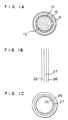
- an inner surface layer 14 in contact with fuel pellet 21 is made of pure zirconium
- an intermediate layer 15 is made of alloy having a relatively high ductility, as shown in Fig. 1A, thereby performing the objects of the invention.
- a surface layers 26 in contact with the reactor water are made of high strength and high corrosion resistance alloy, and an intermediate layer 27 interposed between the surface layers is made of alloy having a high ductility to thereby perform the above-described objects, as shown in Figs. 1B and 1C.
- a Zr-based alloy containing 0.5 to 2.2% Nb-0.5 to 1.5% Sn-0.1 to 0.8% Mo it is preferable to use, as the high ductility alloy, a Zr-based alloy containing 0.5 to 2.0% Sn-0.05 to 0.4% Fe-0.05 to 0.15% Cr-0.03 to 0.2% Ni, a Zr-based alloy containing 0.5 to 2.0% Sn-0.05 to 0.4% Fe-0.03 to 0.2% Ni, a Zr-based alloy containing 0.05 to 2.0% Sn-0.05 to 0.4% Fe-0.05 to 0.15% Cr-0.03 to 0.2% Ni-0.01 to 0.8% Mo, stainless steel or copper alloy.
- a Zr-based alloy containing Nb-Sn-Mo and having preferably a tensile strength of 70 kgf/mm2 or more at room temperature is used in a surface in contact with the reactor water, it is possible to prevent the nodular corrosion and to increase the strength of the member. Furthermore, the degree of the hydrogen absorption of these alloys is small at about 1/5 of that of zircaloy-2 and zircaloy-4. It is thus possible to prevent the hydrogen embrittlement.
- a high ductility alloy preferably with tensile strength of 45 to 60 kgf/mm2 at room temperature and with an elongation rate 25% or more is used as an intermediate layer interposed between the above-described high strength high corrosion resistance alloy which intermediate layer is out of contact with the fuel pellet, or as an intermediate layer interposed between a pure Zr liner layer, which preferably has a tensile strength of 30 to 40 kgf/mm2 and an elongation rate 30% or more, and the high strength high corrosion resistance alloy, the ductility of the member is enhanced, and in particular, the toughness of a member such as a spacer that is subjected to a impact load during the fuel handling is enhanced.
- the elongation rate is preferable 30% or more.
- the intermediate layer As a material forming the intermediate layer, other than those described above, it is preferable to use copper alloy and stainless steel.
- the tensile strength of these materials at room temperature is shown in Table 1.
- the alloy composition must meet the following relationship: [Sn addition amount] (wt%) ⁇ 2 x [Nb addition amount] (wt%) -3.0
- the alloy should be heat-treated in the temperature range of 500 to 700°C after welding. In particular, it is preferable to effect the heat treatment for heating the alloy for 1 to 30 hours in the temperature range of 530 to 610°C.
- the causes for the degradation in corrosion resistance property of the weld zone and the heat-affected zone thereof are that a non-equilibrium phase in which a great amount of Nb exists in a solid-solution state is formed during a heating/cooling process in welding.
- the non-equilibrium phase is formed in such a manner that ⁇ phase stable at a high temperature is formed in the weld zone and the heat-affected zone thereof and is quenched.
- the ⁇ phase remains at the room temperature, or is not decomposed into an ⁇ -Zr phase and a ⁇ -Nb precipitated phase stable at room temperature in the cooling process, and the ⁇ phase is martensite-transformed into ⁇ Zr phase.
- the corrosion resistance property of this phase is extremely low, which causes the reduction in anti-corrosion property in weld zone.
- the purpose of the heat treatment after welding is to decompose the non-equilibrium phase into the ⁇ -Zr phase and the ⁇ -Nb precipitated phase stable at room temperature.
- Sn has an effect for preventing the generation of the non-equilibrium phase during the cooling process in welding and an effect for accelerating the decomposition of the non-equilibrium phase still remaining after welding.
- the upper limit of preferable temperature range is 610°C is that, if the alloy is heated above the upper limit, the ⁇ phase will be again formed and the ⁇ Nb phase that is finely precipitated in the ⁇ Zr phase to enhance the strength will be diffused into the ⁇ phase to thereby remarkably reduce the strength.
- the reason why the lower limit of the preferable temperature range is 530°C is that the worked structure generated by cold working or the like is heated at 530°C or above so as to be recrystallized for enhancing the ductility of the material and for promoting the decomposition of the non-equilibrium phase remaining in the welded portions.
- the heating in the temperature range of 530 to 610°C is performed for the purposes of preventing the crystalline particle of the high ductility alloy interposed between the high strength high anti-corrosion alloys from becoming coarse and of preventing superior ductility being degraded.
- a thickness of the high strength high anti-corrosion alloy be in the range of 5 to 20%. If the thickness is smaller than the lower limit, it would be very difficult to control the thickness during the manufacture. The upper limit thereof depends upon the necessary strength.
- the thickness of the innermost layer is less than 50 »m, it is difficult to control the thickness during the manufacture. Also, the maximum value is 150 »m in view of I2 SCC of the pure zirconium. Therefore, the thickness of the innermost layer is about 5.8 to 17.4% of the total thickness. Preferably, it is 5 to 20% thereof.
- the thickness of the outermost layer is in the range of 100 to 480 »m, that is, in the range of about 11.6 to 55.8% of the total thickness. It is preferable the range of the thickness of the outermost layer be 10 to 60%, and in particular, in case of a cladding tube, it is preferable that the thickness of the outermost layer be 15 to 30%, and as other requisite, it is preferable to make the thickness of a single layer be in the range of 20 to 35%.
- the maximum and minimum values are varied depending upon the mechanical strength of the material to be used.
- An example of the maximum and minimum values in case of the intermediate layer of copper alloy or stainless steel is shown in Table 2. It is preferable to set the thickness of the intermediate layer in the range of 25 to 85%. In particular, in case of the cladding tube, it is preferable to set the intermediate layer thickness in the range of 50 to 70%, and in case of other members, it is preferable to set the intermediate layer thickness in the range of 35 to 60%.
- Interfaces of the three-layer structure are preferably a metallurgically bonded faces.
- Fig. 6 is a view showing an example of a process for producing the fuel structural member according to the present invention.
- the integration is performed by the mutual diffusion of metal atoms between the materials at the time of hot rolling or hot extruding and intermediate annealing after cold rolling.
- a stable phase such as an oxide film is formed on a surface of the material, this phase becomes a barrier against the mutual diffusion, resulting in inferior metallurgical bonding. Accordingly, any work that contaminate the surface must be avoided.
- the materials forming the respective layers are overlapped with each other. At this time, end faces thereof are welded together to prevent air or the like from entering into the interior.
- the welding work is performed in the atmosphere, there is a fear that an oxide layer is formed in the interface in welding. Therefore, it is preferable to perform the welding work under vacuum condition.
- the water cooling rate be 8°C/sec or more. If the cooling rate is lower than this limit, the precipitated phase will become coarse, to degrade the mechanical property.
- the cold rolling and annealing must be performed at least once. Since the ductility of the material cooled from the ⁇ + ⁇ phase or the ⁇ phase is low, it is necessary to grow new crystalline perticles having no strain by heating the material above the recrystallization temperature after forming a working structure through the cold rolling. This treatment recovers the ductility.
- Each of the ingots was forged at a temperature of 980 to 1050°C ( ⁇ forging) and the forged billets were formed into billets having diameters different each other.
- the forged billets were subjected to a heat-treatment ( ⁇ quenching) in which the billets were water-cooled after being held at 1000°C for one hour.
- the billets were subjected to piercing so that the billets were provided with axial holes of diameters different each other.
- the inner diameter of the hole provided in the Zr-Sn-Fe-Nb-Mo alloy pierced cylindrical billet was approximately equal to the outer diameter of the hole provided in the Zr-Sn-Fe-Ni-Cr alloy pierced cylindrical billet, the latter being inserted in the former by use of a press.
- the outer diameter of the hole provided in the pure Zr billet was approximately equal to the inner diameter of the pierced Zr-Sn-Fe-Ni-Cr alloy billet, the pure Zr billet being inserted in the latter billet by use of the press so that the three billets were integrated.
- the inner diameter of the integrated billets was made to be 50 mm and the outer diameter thereof was made to be 150 mm, in which integrated billets the thickness of the Zr-Sn-Nb-Mo alloy was 10 mm, the thickness of the Zr-Sn-Fe-Ni alloy being 30 mm, and the thickness of the pure Zr being 10 mm.
- the boundary portions of the ends of the intergrated billets were welded under a high vacuum not less than 1x10 ⁇ 4 Torr by an electron beam welding device.
- the integrated billets were hot-extruded after being heated to 750°C, with the result that there was produced a tube having an outer diameter of 64 mm and a thickness of 11 mm.
- the tube was cold-rolled two times by use of pilger mills, so that there was obtained a tube having an outer diameter of 19.2 mm and a thickness of 1.9 mm.
- an intermediate annealing treatment was effected at 630°C in 2 hours after the first cold-rolling, then the tube was subjected to a heat-treatment ( ⁇ + ⁇ quenching) in which water was jetted onto the tube to effect the cooling thereof just after the tube passed a high frequency induction coil.
- a heat-treatment ⁇ + ⁇ quenching
- the tube was again rolled two times by the pilger mills to thereby obtain a tube having an outer diameter of 12.3 mm and a thickness of 0.86 mm, the intermediate annealing being effected at 590°C in 2 hours, and the final annealing was effected under vacuum at 570°C for 2 hours.
- test pieces From both the weld zone and the center portion of the resultant fuel rod there were cut out test pieces, which were subjected to a corrosion test and a tensile test.
- the corrosion test was effected at a temperature of 500°C in steam of a pressure of 105 kgf/cm2 by holding them in 24 hours.
- Other test pieces were polished and etched to examine the thickness of each layer.
- the cross-sectional thickness of the pure Zr was 18% of the whole thickness of the fuel cladding tube, that the thickness of the Zr-Sn-Fe-Ni-Cr alloy layer is 62% thereof, and that the thickness of the Zr-Sn-Nb-Mo alloy layer is 20% thereof, that is, the thickness ratio of the layers was in proportion to the thickness ratio of the initial billets forming the integrated billets.
- the tensile strength of the material of the invention was 63 kgf/mm2, the elongation thereof being 38%, so that the tensile strength of the material of the invention is higher by 5 to 8 kgf/mm2 than a conventional fuel cladding tube made of Zircalloy-2 and the elongation of the material of the invention is in the same degree in comparison therewith.
- the ingots were forged at a temperature of 980 to 1050°C to provide slabs of 75 mm in thickness.
- the forged slabs was subjected to ⁇ quenching in which the water cooling thereof was effected after holding the slabs at a temperature of 1000 to 1050°C in 20 minutes.
- the alloy No. 1 shown in Table 5 was hot-rolled at a temperature of 600°C to have a thickness of 35 mm, the alloy No. 2 being hot-rolled at a temperature of 750°C to have a thickness of 20 mm.
- the surfaces of both the alloys were finished by mechanical grinding. Then, the finished alloy No. 1 was sandwiched between two pieces of plates of the alloy No. 2.
- the end faces of the three pieces of plates overlapped each other were integrated by electron beam welding, which integrated plates were hot-rolled two times at 780°C to provide sheet having a thickness of 3 mm, which sheet was further cold-rolled to have a thickness of 2 mm and was subjected to an annealing treatment in which it was held at 650°C in 2 hours. After that, it was held at 870°C in 5 minutes and then cooled by jetting water onto both surfaces of the sheet.
- the sheet was further cold-rolled three times to provide a strip used for a spacer which strip had a thickness of 0.53 mm.
- Annealing was effected between adjacent two cold-rollings at 590°C in 1 hour, while the final annealing was effected at 570°C in 1 hour. From the strip there was formed a spacer band shown in Fig. 4B by punching, and it was subjected to a dimple working.
- the billet of the alloy No. 1 (the intermediate layer billet) was sandwiched by the outer and inner two billets (the outer and inner surface layer billets) of the alloy No. 2 shown in Table 5, which outer surface layer billet of the alloy No. 2 had an outer diameter of 150 mm and a thickness of 15 mm, which intermediate layer billet had a thickness of 20 mm, and which inner surface layer billet had a thickness of 15 mm.
- the production process thereof was the same as the embodiment 1 with the exception of the size as shown above, that is, the end faces defined by those of the billets in a sandwich state was integrated by electron beam welding and then the integrated billets were hot-rolled at 750°C to provide a tube having an outer diameter of 64 mm and a thickness of 11 mm, which tube was rolled one time by a pilger mill to obtain a tube having an outer diameter of 34.9 mm and a thickness of 4.4 mm. The whole length of the tube was then subjected to a treatment in which it was heated to 870°C while passing a high frequency induction heating coil portion and water was jetted thereon to quench the tube at the position just under the heating portion.
- the treatment After the treatment, it was heat-treated at 600°C for 1 hour. Further, the cold working and intermediate annealing were alternately effected three times to obtain a tube having an outer diameter of 14 mm and a thickness of 0.6 mm, the temperature of which intermediate annealing was 590°C.
- the tube was cut to obtain tube members each having a length of 25 mm, which members were plastically worked with a plate spring 28 being attached to each of the tube member so that the tube members was formed into a spacer ring 25 of such configuration as a fuel rod was able to be held in each of the tube members.
- spacer rings were assembled to form a rounded cell type spacer lattice of 9x9 pieces, spacer band 22 being disposed around the outer periphery of the lattice and being spot-welded to thereby obtain a rounded type spacer. After the completion of the assembling thereof, the whole was heat-treated by holding it at 530°C for 10 hours.
- test pieces From the spacer there were cut out test pieces a part of which included a weld zone, the test pieces being subjected to corrosion test in steam of 500°C.
- the content of hydrogen contained in the material of the invention was analyzed, so that the hydrogen absorption rate thereof was 3%.
- a plate material made of the alloy No. 1 alone and another plate material made of the alloy No. 2 alone were subjected to corrosion test in high temperature water, and the hydrogen absorption rates thereof were measured with the results that the hydrogen absorption rate of the alloy No. 1 was 35% while the hydrogen absorption rate of the alloy No. 2 was 3%.
- the hydrogen absorption rate of the structure members of the fuel assembly for nuclear reactor according to the invention is the same level as the alloy No. 2.
- a plate of the alloy No. 2 alone provided with a notch was subjected to impact test with the result that the absorption energy thereof was a low value of 3 kg ⁇ m/mm2, while the absorption energy of the plate of three-layer structure of the invention was 20 kg ⁇ m/mm2 which was a very improved value in comparison with the former.
- the final annealing was effected at 600°C in 2 hours.
- This sheet was bent to a channel shape, by use of which sheet there was produced a tube of a square cross section by TIG welding. After the welding, bead portions occurring in the welding were flattened by rolling. Thereafter, a mandrel made of a stainless steel was inserted in the interior of the tube of square cross-section, which tube was then held at 600°C in 2 hours. During this heat treatment, the square tube was plastically deformed in compliance with the shape of the mandrel because the linear expansion coefficient of the stainless steel is higher than that of the structural member, so that the square tube was formed to have a predetermined size.
- Test pieces were cut out from the weld zone of the channel box thus produced and were subjected to corrosion test, with the result that the same high corrosion resistance as in the Embodiments 1 and 2 was able to be confirmed.
- the invention it is possible to prevent nodular corrosion from occurring and to prevent accelerated corrosion from occurring inherently in a weld zone of an alloy containing Nb. Further, in the invention it is also possible to reduce the hydrogen absorption rate into a degree of not more than 1/10 in comparison with that of the conventional Zircalloy shown in Table 5 and at the same time it is possible to enhance toughness against impact load. Thus, in the invention it is possible to greatly prolong the service life period of a fuel construction member disposed in a nuclear reactor, so that there can be obtained a fuel assembly for nuclear reactor and a member thereof both sufficiently compatible with a tendency to make the degree of burn-up of fuel higher.
Landscapes
- Engineering & Computer Science (AREA)
- Physics & Mathematics (AREA)
- Plasma & Fusion (AREA)
- General Engineering & Computer Science (AREA)
- High Energy & Nuclear Physics (AREA)
- Metallurgy (AREA)
- Fuel-Injection Apparatus (AREA)
- Monitoring And Testing Of Nuclear Reactors (AREA)
- Arc Welding In General (AREA)
- Other Surface Treatments For Metallic Materials (AREA)
Claims (25)
- Strukturteil für eine Brennelementkassette eines Kernreaktors mit einer Dreischichtstruktur, die aufweist:
eine innere Oberflächenschicht, eine äußere Oberflächenschicht und eine dazwischen angeordnete Zwischenschicht, wobei die äußere Oberflächenschicht und gegebenenfalls die innere Oberflächenschicht in Kontakt mit dem Reaktorwasser des Kernreaktors ist bzw. sind,
dadurch gekennzeichnet, daß
die äußere Oberflächenschicht und gegebenenfalls die innere Oberflächenschicht aus einer Zirkoniumlegierung besteht bzw. bestehen die Nb, Sn und Mo enthält und dadurch, daß die Zwischenschicht aus einer Legierung mit hoher Verformbarkeit besteht, deren Verformbarkeit größer ist als die der äußeren Oberflächenschicht und deren Festigkeit größer ist als die der inneren Oberflächenschicht. - Strukturteil nach Anspruch 1,
dadurch gekennzeichnet, daß
das Teil ein Brennstoffhüllrohr (11) ist und wobei die innere Oberflächenschicht (14) mit dem Kernbrennstoff (21) in Kontakt steht, wobei die innere Oberflächenschicht (14) aus reinem Zirkonium besteht und die Zwischenschicht (15) aus einer hochduktilen Legierung besteht, deren Verformbarkeit größer ist als die der äußeren Oberflächenschicht (16) und deren Festigkeit größer ist als die der inneren Oberflächenschicht (14). - Strukturteil nach Anspruch 1,
dadurch gekennzeichnet, daß
das Teil ein Brennstoffabstandshalter (2) ist. - Strukturteil nach Anspruch 1,
dadurch gekennzeichnet, daß
das Teil eine Brennstoff-Channelbox (3) ist. - Strukturteil für Kernreaktoren nach einem der Ansprüche 1 bis 4, wobei eine Zirkoniumlegierung mit Nb, Sn und Mo die äußere Oberflächenschicht (16; 26; 31) bildet und gegebenenfalls die innere Oberflächenschicht 0,5 bis 2,2 Gew.% Nb, 0,5 bis 1,5 Gew.% Sn sowie 0,1 bis 0,8 Gew.% Mo aufweist, wobei der Rest aus Zirkonium und nicht vermeidbaren Verunreinigungen besteht.
- Strukturteil für Kernreaktoren nach einem der Ansprüche 1 bis 5, wobei die hochduktile Legierung, aus der die Zwischenschicht (15; 27) besteht, aus einer Legierung auf Zirkoniumbasis besteht, die Sn, Fe und Ni aufweist.
- Strukturteil für Kernreaktoren nach Anspruch 6, wobei die Legierung hoher Duktilität aus der die Zwischenschicht (15; 27) besteht aus 0,5 bis 2 Gew.% Sn, 0,05 bis 0,4 Gew.% Fe, 0,03 bis 0,2 Gew.% Ni und dem Rest Zirkonium sowie unvermeidbaren Verunreinigungen besteht.
- Strukturteil für Kernreaktoren nach einem der Ansprüche 1 bis 5, wobei die hochduktile Legierung, aus der die Zwischenschicht (15; 27) besteht, eine Legierung auf Zirkoniumbasis ist, die Sn, Fe, Ni und Cr aufweist.
- Strukturelement für Kernreaktoren nach Anspruch 8, bei dem die hochduktile Legierung, aus der die Zwischenschicht (15; 27) besteht 0,5 bis 2 Gew.% Sn, 0,05 bis 0,4 Gew.% Fe, 0,03 bis 0,2 Gew.% Ni, 0,05 bis 0,15 Gew.% Cr, Rest Zirkonium und unvermeidbare Verunreinigungen, aufweist.
- Strukturelement für Kernreaktor nach einem der Ansprüche 1 bis 5, wobei die hochduktile Legierung, aus der die Zwischenschicht (15; 27) besteht, eine Zirkoniumlegierung ist, die Sn, Fe, Ni, Cr und Mo aufweist.
- Strukturteil für Kernreaktoren nach Anspruch 10, wobei die hochduktile Legierung, aus der die Zwischenschicht (15; 27) besteht, aus 0,5 bis 2 Gew.% Sn, 0,05 bis 0,4 Gew.% Fe, 0,03 bis 0,2 Gew.% Ni, 0,05 bis 0,15 Gew.% Cr, 0,01 bis 0,8 Gew.% Mo und dem Rest Zirkonium sowie unvermeidbaren Verunreinigungen besteht.
- Strukturteil für Kernreaktor nach einem der Ansprüche 1 bis 5, wobei die hochduktile Legierung, aus der die Zwischenschicht (15; 27) besteht aus 0,1 bis 0,7 Gew.% Nb, und dem Rest Zirkonium und unvermeidbaren Verunreinigungen besteht.
- Strukturteil für Kernreaktor nach einem der Ansprüche 1 bis 5, wobei die hochduktile Legierung, aus der die Zwischenschicht (15; 27) besteht, ein rostfreier Stahl ist, der nicht mehr als 0,08 Gew.% C, nicht mehr als 2 Gew.% Mn und nicht mehr als 1 Gew.% Si sowie 16,0 bis 20,0 Gew.% Cr, 8,00 bis 14,00 Gew.% Ni und nicht mehr als 3 Gew.% Mo, Rest Eisen und Verunreinigungen aufweist.
- Strukturteil für Kernreaktor nach einem der Ansprüche 1 bis 5, wobei die hochduktile Legierung, aus der die Zwischenschicht (15; 27) besteht eine Kupferlegierung ist, die aus nicht mehr als 3 Gew.% Pb, nicht mehr als 6 Gew.% Fe, nicht mehr als 0,5 Gew.% Zn, nicht mehr als 11 Gew.% Al, nicht mehr als 2 Gew.% Mn, nicht mehr als 33 Gew.% Ni sowie dem Rest Kupfer und Verunreinigungen besteht.
- Strukturteil für Kernreaktor nach einem der Ansprüche 2 und 4 bis 14, wobei bei dem Brennstoffhüllrohr (11) die Dicke der äußeren Oberflächenschicht (16) und gegebenenfalls die Dicke der inneren Oberflächenschicht, die in Kontakt mit dem Reaktorwasser des Kernreaktors steht, 10 bis 30 % der Gesamtdicke des Hüllrohrs (11) ausmacht bzw. ausmachen und in der Channelbox (3) die Dicke der äußeren Oberflächenschicht (31) in Kontakt mit dem Reaktorwasser 20 bis 35 % der Gesamtdicke der Channelbox ausmacht.
- Verfahren zur Herstellung eines Strukturteils für eine Brennelementkassette für Kernreaktoren, wobei das Strukturteil eine Dreischichtstruktur aufweist mit:
einer inneren Oberflächenschicht, einer äußeren Oberflächenschicht und einer Zwischenschicht, wobei die äußere Oberflächenschicht und gegebenenfalls die innere Oberflächenschicht in Kontakt mit dem Reaktorwasser des Kernreaktors steht bzw. stehen,
dadurch gekennzeichnet, daß
die äußere Oberflächenschicht und gegebenenfalls die innere Oberflächenschicht aus einer Zirkoniumlegierung besteht bzw. bestehen, die Nb, Sn und Mo aufweist bzw. aufweisen, die Zwischenschicht aus einer hochduktilen Legierung besteht, deren Verformbarkeit größer ist als die der äußeren Oberflächenschicht und die fester ist als die innere Oberflächenschicht, wobei das Verfahren folgende Schritte aufweist: Integration durch thermisches verbinden der dreischichtigen Struktur mit der Zwischenschicht und der inneren und äußeren Oberflächenschichten, wobei die integrierte dreischichtige Struktur einer Wärmebehandlung unterzogen wird, so daß die Struktur aufgeheizt wird, und auf einer Temperatur gehalten wird, in der die α- + β-Phase der Legierung auf Zirkoniumbasis oder die β-Phase der Legierung auf Zirkoniumbasis erhalten werden, und wobei die Struktur nach dem Aufheizen abgeschreckt wird und einer Kaltverformung und einem Ausglühen unterzogen wird, um Teile geringer Dicke zu erzeugen, wobei die verformung und das Verschweißen der dünnen Teile durchgeführt wird, um Strukturteile der gewünschten Form zu erhalten und wobei die Strukturteile einer Wärmebehandlung bei einer Temperatur zwischen 400 und 700 °C unterzogen werden. - Verfahren nach Anspruch 16,
dadurch gekennzeichnet, daß
das Teil ein rohrförmiges oder plattenförmiges Teil ist und daß der Schritt der Wärmebehandlung bei einer Temperatur von 400 bis 700 °C ausgeführt wird, nachdem die Endflächen des Teils verschweißt sind. - Verfahren nach Anspruch 16 zur Erzeugung des Strukturteils für Kernreaktoren nach einem der Ansprüche 2 und 5 bis 15, wobei das Brennstoffhüllrohr (11) durch ein Verfahren hergestellt wird mit folgenden Schritten: Einführen eines zylinderförmigen Rohlings aus einer Legierung, welcher eine Zwischenschicht (15) wird, in einen anderen zylinderförmigen Rohling, der zur äußeren Oberflächenschicht (16) wird, die in Kontakt mit dem Reaktorwasser des Kernreaktors steht, Einführen eines zylinderförmigen Rohlings, welcher die innere Oberflächenschicht (14) wird, in den Rohling für die Zwischenschicht (15), Zusammenfügen all dieser Rohlinge durch verschweißen ihrer Endflächen und Ziehen der zusammengefügten Rohling bei einer Temperatur von 500 bis 800 °C und mehrmaliges Wiederholen sowohl der Kaltverformung als auch des Glühens.
- Verfahren nach Anspruch 16 zur Herstellung des Strukturteils für Kernreaktor nach einem der Ansprüche 3 und 5 bis 15, wobei der zylinderförmige Brennstoffabstandshalter (2) durch ein Verfahren hergestellt wird mit folgenden Schritten: Einführen eines zylinderförmigen Rohlings aus einer Legierung, der zu der Zwischenschicht (27) wird, in einen weiteren zylinderförmigen Rohling, der zur äußeren Oberflächenschicht (26) in Kontakt mit dem Reaktorwasser des Kernreaktors wird, Einfügen eines zylinderförmigen Rohlings, der zur inneren Oberflächenschicht wird und der aus demselben Material besteht wie die äußere Oberflächenschicht (26), in den Rohling für die Zwischenschicht (27), Zusammenfügen aller Rohlinge durch Verschweißen der jeweiligen Endflächen, Ziehen der verbundenden Rohlinge bei einer Temperatur von nicht weniger als 610 °C und wiederholtes Kaltverformen und Glühen.
- Verfahren nach Anspruch 18 und 19, wobei das Verschweißen unter einem Druck nicht größer als 1 x 10⁻⁴ Torr stattfindet.
- Verfahren nach Anspruch 18 und 19, wobei das zwischenzeitliche Glühen zwischen aufeinanderfolgenden Kaltverformungen bei einer Temperatur von 610 bis 750 °C stattfindet.
- Verfahren nach den Ansprüchen 18 bis 21, wobei mindestens ein Teil des Brennstoffhüllrohrs (11) und des zylinderförmigen Brennstoffabstandhalters (2) einer Wärmebehandlung unterzogen wird, die die Schritte aufweist: Aufheizen der Oberflächenschicht oder Aufheizen der Gesamtdicke des Hüllrohrs (11) bei einer Temperatur von 800 bis 900 °C nach der abschließenden Warmverformung, jedoch vor der abschließenden Kaltverformung und anschließendes Abschrecken.
- Verfahren nach Anspruch 16 zur Herstellung des Strukturteils für Kernreaktoren nach einem der Ansprüche 3 bis 15, wobei mindestens einer des Brennstoffabstandhalters (2) und der Brennstoff-Channelbox (3) durch ein Verfahren hergestellt wird, welches folgende Schritte aufweist: Einfügen einer Platte aus einer Legierung, die zu der Zwischenschicht (27) wird, zwischen Platten, die zur äußeren Oberflächenschicht, die in Kontakt mit dem Reaktorwasser des Kernreaktors ist, wird, Zusammenfügen der Platten durch Verschweißen ihrer Endflächen und Ziehen der zusammengefügten Teile bei einer Temperatur von 500 bis 800 °C sowie wiederholtes Kaltverformen und Glühen.
- Verfahren nach Anspruch 23, wobei ein Zwischenglühen zwischen zwei aufeinanderfolgenden Kaltverformungen bei einer Temperatur von 610 bis 750 °C durchgeführt wird.
- Verfahren nach Anspruch 23 und 24, wobei mindestens einer des Brennstoffabstandhalters (2) und der Brennstoff-Channelbox (3) einer Wärmebehandlung unterzogen wird mit folgenden Schritten: Aufheizen auf eine Temperatur von 800 bis 900 °C nach der letzten Warmverformung, jedoch vor der letzten Kaltverformung bezüglich wenigstens entweder dem Brennstoffhüllrohr (11) und dem zylinderförmigen Brennstoffabstandshalter (2) und anschließendes Abschrecken.
Applications Claiming Priority (2)
| Application Number | Priority Date | Filing Date | Title |
|---|---|---|---|
| JP63192982A JP2580273B2 (ja) | 1988-08-02 | 1988-08-02 | 原子炉用燃料集合体およびその製造方法並びにその部材 |
| JP192982/88 | 1988-08-02 |
Publications (3)
| Publication Number | Publication Date |
|---|---|
| EP0353733A2 EP0353733A2 (de) | 1990-02-07 |
| EP0353733A3 EP0353733A3 (en) | 1990-03-07 |
| EP0353733B1 true EP0353733B1 (de) | 1994-06-15 |
Family
ID=16300268
Family Applications (1)
| Application Number | Title | Priority Date | Filing Date |
|---|---|---|---|
| EP89114266A Expired - Lifetime EP0353733B1 (de) | 1988-08-02 | 1989-08-02 | Brennstoffanordnung für einen Kernreaktor, Verfahren zu deren Herstellung und Strukturteil dafür |
Country Status (4)
| Country | Link |
|---|---|
| US (1) | US5225154A (de) |
| EP (1) | EP0353733B1 (de) |
| JP (1) | JP2580273B2 (de) |
| DE (1) | DE68916124T2 (de) |
Families Citing this family (29)
| Publication number | Priority date | Publication date | Assignee | Title |
|---|---|---|---|---|
| JP2560571B2 (ja) * | 1991-07-15 | 1996-12-04 | 株式会社日立製作所 | 燃料チャンネルボックスの製造方法及び燃料チャンネルボックス |
| FI923892L (fi) * | 1991-09-16 | 1993-03-17 | Siemens Power Corp | Strukturella element foer en kaernreaktors braenslestavsmontering |
| US5223206A (en) * | 1992-06-08 | 1993-06-29 | General Electric Company | Method for producing heat treated composite nuclear fuel containers |
| US5416813A (en) * | 1992-10-30 | 1995-05-16 | Kabushiki Kaisha Toshiba | Moderator rod containing burnable poison and fuel assembly utilizing same |
| US5285485A (en) * | 1993-02-01 | 1994-02-08 | General Electric Company | Composite nuclear fuel container and method for producing same |
| US5469481A (en) * | 1993-07-14 | 1995-11-21 | General Electric Company | Method of preparing fuel cladding having an alloyed zirconium barrier layer |
| US5383228A (en) * | 1993-07-14 | 1995-01-17 | General Electric Company | Method for making fuel cladding having zirconium barrier layers and inner liners |
| US5341407A (en) * | 1993-07-14 | 1994-08-23 | General Electric Company | Inner liners for fuel cladding having zirconium barriers layers |
| US5434897A (en) * | 1994-03-21 | 1995-07-18 | General Electric Company | Hydride damage resistant fuel elements |
| US5805656A (en) * | 1996-04-08 | 1998-09-08 | General Electric Company | Fuel channel and fabrication method therefor |
| US5838753A (en) * | 1997-08-01 | 1998-11-17 | Siemens Power Corporation | Method of manufacturing zirconium niobium tin alloys for nuclear fuel rods and structural parts for high burnup |
| US6233299B1 (en) * | 1998-10-02 | 2001-05-15 | Japan Nuclear Cycle Development Institute | Assembly for transmutation of a long-lived radioactive material |
| US20020106048A1 (en) * | 2001-02-02 | 2002-08-08 | General Electric Company | Creep resistant zirconium alloy and nuclear fuel cladding incorporating said alloy |
| KR100461017B1 (ko) * | 2001-11-02 | 2004-12-09 | 한국수력원자력 주식회사 | 우수한 내식성을 갖는 니오븀 함유 지르코늄 합금핵연료피복관의 제조방법 |
| JP4095920B2 (ja) * | 2003-03-31 | 2008-06-04 | 株式会社資生堂 | 複合粉末、それを配合した化粧料、及び複合粉末の製造方法 |
| ES2336338T3 (es) | 2004-01-15 | 2010-04-12 | Westinghouse Electric Sweden Ab | Separador y unidad de combustible para una central nuclear. |
| SE526381C2 (sv) * | 2004-01-15 | 2005-09-06 | Westinghouse Electric Sweden | Spridare och bränsleenhet för en nukleär anläggning |
| SE528120C2 (sv) | 2004-07-06 | 2006-09-05 | Westinghouse Electric Sweden | Förfarande för framställning av plåt för användning i en kokarvattenkärnreaktor, plåt samt förfarande för framställning av bränslebox, samt bränslebox |
| WO2006004499A1 (en) * | 2004-07-06 | 2006-01-12 | Westinghouse Electric Sweden Ab | Fuel box in a boiling water nuclear reactor |
| SE530673C2 (sv) * | 2006-08-24 | 2008-08-05 | Westinghouse Electric Sweden | Vattenreaktorbränslekapslingsrör |
| US20090285350A1 (en) * | 2008-05-19 | 2009-11-19 | Global Nuclear Fuel-Americas, Llc | Multi-layer fuel channel and method of fabricating the same |
| US8784726B2 (en) * | 2008-09-18 | 2014-07-22 | Terrapower, Llc | System and method for annealing nuclear fission reactor materials |
| US8529713B2 (en) | 2008-09-18 | 2013-09-10 | The Invention Science Fund I, Llc | System and method for annealing nuclear fission reactor materials |
| US8721810B2 (en) | 2008-09-18 | 2014-05-13 | The Invention Science Fund I, Llc | System and method for annealing nuclear fission reactor materials |
| US9287012B2 (en) | 2010-07-25 | 2016-03-15 | Global Nuclear Fuel—Americas, LLC | Optimized fuel assembly channels and methods of creating the same |
| JP6194536B2 (ja) * | 2012-09-18 | 2017-09-13 | 国立研究開発法人日本原子力研究開発機構 | 燃料棒の被覆管試験片作製方法及びこれに使用する内面保護栓 |
| US10217533B2 (en) * | 2013-08-30 | 2019-02-26 | Electric Power Research Institute, Inc. | Fuel rod cladding and methods for making and using same |
| CN106128532B (zh) * | 2016-06-12 | 2018-10-12 | 上海核工程研究设计院 | 一种核燃料元件包壳锆合金钛合金复合管及其制备方法 |
| WO2018023178A1 (pt) * | 2016-08-03 | 2018-02-08 | Indústrias Nucleares Do Brasil Sa - Inb | Composição de liga metálica a base de zircõnio dotada de elevada propriedade mecânica e alta resistência à corrosão e fragilização, destinada à composição de parte estrutural de componentes de reator nuclear e ao revestimento de elemento combustível nuclear |
Family Cites Families (23)
| Publication number | Priority date | Publication date | Assignee | Title |
|---|---|---|---|---|
| US3121034A (en) * | 1962-03-13 | 1964-02-11 | Anderko Kurt | Zirconium alloy treatment process |
| US3620691A (en) * | 1964-04-11 | 1971-11-16 | Siemens Ag | Zirconium structure |
| NO130993C (de) * | 1973-07-09 | 1975-03-25 | Atomenergi Ab | |
| US3925151A (en) * | 1974-02-11 | 1975-12-09 | Gen Electric | Nuclear fuel element |
| US4045288A (en) * | 1974-11-11 | 1977-08-30 | General Electric Company | Nuclear fuel element |
| CA1027781A (en) * | 1975-05-06 | 1978-03-14 | Brian A. Cheadle | High strength sn-mo-nb-zr alloy tubes and method of making same |
| US4372817A (en) * | 1976-09-27 | 1983-02-08 | General Electric Company | Nuclear fuel element |
| US4238251A (en) * | 1977-11-18 | 1980-12-09 | General Electric Company | Zirconium alloy heat treatment process and product |
| US4390497A (en) * | 1979-06-04 | 1983-06-28 | General Electric Company | Thermal-mechanical treatment of composite nuclear fuel element cladding |
| US4452648A (en) * | 1979-09-14 | 1984-06-05 | Atomic Energy Of Canada Limited | Low in reactor creep ZR-base alloy tubes |
| US4445942A (en) * | 1979-11-26 | 1984-05-01 | General Electric Company | Method for forming nuclear fuel containers of a composite construction and the product thereof |
| US4613479A (en) * | 1984-03-14 | 1986-09-23 | Westinghouse Electric Corp. | Water reactor fuel cladding |
| US4664881A (en) * | 1984-03-14 | 1987-05-12 | Westinghouse Electric Corp. | Zirconium base fuel cladding resistant to PCI crack propagation |
| US4649023A (en) * | 1985-01-22 | 1987-03-10 | Westinghouse Electric Corp. | Process for fabricating a zirconium-niobium alloy and articles resulting therefrom |
| FR2579122B1 (fr) * | 1985-03-19 | 1989-06-30 | Cezus Co Europ Zirconium | Procede de fabrication de tubes-gaines composites pour combustible nucleaire et produits obtenus |
| US4671826A (en) * | 1985-08-02 | 1987-06-09 | Westinghouse Electric Corp. | Method of processing tubing |
| US4717428A (en) * | 1985-08-02 | 1988-01-05 | Westinghouse Electric Corp. | Annealing of zirconium based articles by induction heating |
| US4751044A (en) * | 1985-08-15 | 1988-06-14 | Westinghouse Electric Corp. | Composite nuclear fuel cladding tubing and other core internal structures with improved corrosion resistance |
| JPH0625389B2 (ja) * | 1985-12-09 | 1994-04-06 | 株式会社日立製作所 | 高耐食低水素吸収性ジルコニウム基合金及びその製造法 |
| US4842814A (en) * | 1986-02-03 | 1989-06-27 | Hitachi, Ltd. | Nuclear reactor fuel assembly |
| JPH0812259B2 (ja) * | 1986-02-18 | 1996-02-07 | 株式会社東芝 | 核燃料要素 |
| FR2624136B1 (fr) * | 1987-12-07 | 1992-06-05 | Cezus Co Europ Zirconium | Tube, barre ou tole en alliage de zirconium, resistant a la fois a la corrosion uniforme et a la corrosion nodulaire et procede de fabrication correspondant |
| US5076488A (en) * | 1989-09-19 | 1991-12-31 | Teledyne Industries, Inc. | Silicon grain refinement of zirconium |
-
1988
- 1988-08-02 JP JP63192982A patent/JP2580273B2/ja not_active Expired - Fee Related
-
1989
- 1989-08-02 EP EP89114266A patent/EP0353733B1/de not_active Expired - Lifetime
- 1989-08-02 US US07/391,316 patent/US5225154A/en not_active Expired - Lifetime
- 1989-08-02 DE DE68916124T patent/DE68916124T2/de not_active Expired - Fee Related
Also Published As
| Publication number | Publication date |
|---|---|
| US5225154A (en) | 1993-07-06 |
| DE68916124T2 (de) | 1994-11-10 |
| JPH0242387A (ja) | 1990-02-13 |
| DE68916124D1 (de) | 1994-07-21 |
| EP0353733A3 (en) | 1990-03-07 |
| EP0353733A2 (de) | 1990-02-07 |
| JP2580273B2 (ja) | 1997-02-12 |
Similar Documents
| Publication | Publication Date | Title |
|---|---|---|
| EP0353733B1 (de) | Brennstoffanordnung für einen Kernreaktor, Verfahren zu deren Herstellung und Strukturteil dafür | |
| US5517541A (en) | Inner liners for fuel cladding having zirconium barriers layers | |
| EP0674800B1 (de) | Erzeugung eines zirkoniumhüllrohres mit innerer beschichtung | |
| EP0674322B1 (de) | Kernreaktorbrennstoffbündel und Verfahren zur Herstellung | |
| JP2638351B2 (ja) | 燃料集合体 | |
| US20100128834A1 (en) | Zirconium alloys with improved corrosion resistance and method for fabricating zirconium alloys with improved corrosion resistance | |
| EP0155167B1 (de) | Hüllen für Kernbrennstoff | |
| US5618356A (en) | Method of fabricating zircaloy tubing having high resistance to crack propagation | |
| JP2941796B2 (ja) | 耐蝕性の原子炉構成部材、核燃料棒被覆管、水性環境に使用するためのジルコニウム合金、および原子炉燃料集成体用構造部材 | |
| US7127024B2 (en) | Fuel element for a pressurized water reactor | |
| JPH07100845B2 (ja) | ジルコニウム合金板の製法 | |
| EP0899747B1 (de) | Verfahren zur Herstellung von Zirkonium-Zinn-Eisen-Legierungen für Kernreaktorbrennstäbe und Bauteile, die einen hohen Abbrand ermöglichen | |
| JPH07224373A (ja) | ジルコニウムまたはジルコニウム合金製のバリヤー被覆の耐蝕性を改良する方法 | |
| EP0529907A1 (de) | Verfahren zum Glühen von Zirkonlegierungen zur Verbesserung der Lochfrasskorrosionsbeständigkeit | |
| EP0549179A1 (de) | Zirkonium-Wismut-Niob-Legierung für Innenauskleidungsschicht von Kernbrennstoffelemente | |
| EP0533073B1 (de) | Strukturbestandteile für Kernreaktorbrennstoffbündel | |
| JPH01119650A (ja) | 原子炉燃料集合体用チヤンネルボツクスの製造方法 | |
| JPS6224182A (ja) | 原子炉燃料被覆管 | |
| US4933136A (en) | Water reactor fuel cladding | |
| EP0937575A1 (de) | Schichtkörper und Brennstoffkassette mit diesem Schichtkörper | |
| EP2122002B1 (de) | Abstandhaltergitter zur positionierung von brennstäben | |
| JP2814981B2 (ja) | 燃料集合体 | |
| EP0195154B1 (de) | Hüllröhre für den Brennstoff eines Wassergekühlten Reaktors | |
| JP2790138B2 (ja) | 高耐食原子燃料用被覆管,スペーサ及びチャンネルボックスとその燃料集合体並びにその製造法 | |
| JPH01116057A (ja) | 原子炉用スペーサの製造法 |
Legal Events
| Date | Code | Title | Description |
|---|---|---|---|
| PUAI | Public reference made under article 153(3) epc to a published international application that has entered the european phase |
Free format text: ORIGINAL CODE: 0009012 |
|
| PUAL | Search report despatched |
Free format text: ORIGINAL CODE: 0009013 |
|
| AK | Designated contracting states |
Kind code of ref document: A2 Designated state(s): DE FR GB |
|
| AK | Designated contracting states |
Kind code of ref document: A3 Designated state(s): DE FR GB |
|
| 17P | Request for examination filed |
Effective date: 19900309 |
|
| 17Q | First examination report despatched |
Effective date: 19920717 |
|
| GRAA | (expected) grant |
Free format text: ORIGINAL CODE: 0009210 |
|
| AK | Designated contracting states |
Kind code of ref document: B1 Designated state(s): DE FR GB |
|
| REF | Corresponds to: |
Ref document number: 68916124 Country of ref document: DE Date of ref document: 19940721 |
|
| ET | Fr: translation filed | ||
| PLBE | No opposition filed within time limit |
Free format text: ORIGINAL CODE: 0009261 |
|
| STAA | Information on the status of an ep patent application or granted ep patent |
Free format text: STATUS: NO OPPOSITION FILED WITHIN TIME LIMIT |
|
| 26N | No opposition filed | ||
| REG | Reference to a national code |
Ref country code: GB Ref legal event code: IF02 |
|
| PGFP | Annual fee paid to national office [announced via postgrant information from national office to epo] |
Ref country code: FR Payment date: 20040722 Year of fee payment: 16 |
|
| PGFP | Annual fee paid to national office [announced via postgrant information from national office to epo] |
Ref country code: GB Payment date: 20040730 Year of fee payment: 16 |
|
| PGFP | Annual fee paid to national office [announced via postgrant information from national office to epo] |
Ref country code: DE Payment date: 20040903 Year of fee payment: 16 |
|
| PG25 | Lapsed in a contracting state [announced via postgrant information from national office to epo] |
Ref country code: GB Free format text: LAPSE BECAUSE OF NON-PAYMENT OF DUE FEES Effective date: 20050802 |
|
| PG25 | Lapsed in a contracting state [announced via postgrant information from national office to epo] |
Ref country code: DE Free format text: LAPSE BECAUSE OF NON-PAYMENT OF DUE FEES Effective date: 20060301 |
|
| GBPC | Gb: european patent ceased through non-payment of renewal fee |
Effective date: 20050802 |
|
| PG25 | Lapsed in a contracting state [announced via postgrant information from national office to epo] |
Ref country code: FR Free format text: LAPSE BECAUSE OF NON-PAYMENT OF DUE FEES Effective date: 20060428 |
|
| REG | Reference to a national code |
Ref country code: FR Ref legal event code: ST Effective date: 20060428 |