EP0353876B1 - Dispositif de freinage de stationnement - Google Patents
Dispositif de freinage de stationnement Download PDFInfo
- Publication number
- EP0353876B1 EP0353876B1 EP89306936A EP89306936A EP0353876B1 EP 0353876 B1 EP0353876 B1 EP 0353876B1 EP 89306936 A EP89306936 A EP 89306936A EP 89306936 A EP89306936 A EP 89306936A EP 0353876 B1 EP0353876 B1 EP 0353876B1
- Authority
- EP
- European Patent Office
- Prior art keywords
- manipulation
- lever
- actuator
- parking brake
- force
- Prior art date
- Legal status (The legal status is an assumption and is not a legal conclusion. Google has not performed a legal analysis and makes no representation as to the accuracy of the status listed.)
- Expired - Lifetime
Links
- 238000006073 displacement reaction Methods 0.000 claims description 53
- 230000008878 coupling Effects 0.000 claims description 37
- 238000010168 coupling process Methods 0.000 claims description 37
- 238000005859 coupling reaction Methods 0.000 claims description 37
- 238000001514 detection method Methods 0.000 claims description 6
- 238000010276 construction Methods 0.000 description 3
- 238000010586 diagram Methods 0.000 description 3
- 230000002265 prevention Effects 0.000 description 3
- 230000005540 biological transmission Effects 0.000 description 1
- 239000003638 chemical reducing agent Substances 0.000 description 1
Images


Classifications
-
- B—PERFORMING OPERATIONS; TRANSPORTING
- B60—VEHICLES IN GENERAL
- B60T—VEHICLE BRAKE CONTROL SYSTEMS OR PARTS THEREOF; BRAKE CONTROL SYSTEMS OR PARTS THEREOF, IN GENERAL; ARRANGEMENT OF BRAKING ELEMENTS ON VEHICLES IN GENERAL; PORTABLE DEVICES FOR PREVENTING UNWANTED MOVEMENT OF VEHICLES; VEHICLE MODIFICATIONS TO FACILITATE COOLING OF BRAKES
- B60T7/00—Brake-action initiating means
- B60T7/02—Brake-action initiating means for personal initiation
- B60T7/08—Brake-action initiating means for personal initiation hand actuated
-
- B—PERFORMING OPERATIONS; TRANSPORTING
- B60—VEHICLES IN GENERAL
- B60T—VEHICLE BRAKE CONTROL SYSTEMS OR PARTS THEREOF; BRAKE CONTROL SYSTEMS OR PARTS THEREOF, IN GENERAL; ARRANGEMENT OF BRAKING ELEMENTS ON VEHICLES IN GENERAL; PORTABLE DEVICES FOR PREVENTING UNWANTED MOVEMENT OF VEHICLES; VEHICLE MODIFICATIONS TO FACILITATE COOLING OF BRAKES
- B60T11/00—Transmitting braking action from initiating means to ultimate brake actuator without power assistance or drive or where such assistance or drive is irrelevant
- B60T11/10—Transmitting braking action from initiating means to ultimate brake actuator without power assistance or drive or where such assistance or drive is irrelevant transmitting by fluid means, e.g. hydraulic
- B60T11/103—Transmitting braking action from initiating means to ultimate brake actuator without power assistance or drive or where such assistance or drive is irrelevant transmitting by fluid means, e.g. hydraulic in combination with other control devices
-
- B—PERFORMING OPERATIONS; TRANSPORTING
- B60—VEHICLES IN GENERAL
- B60T—VEHICLE BRAKE CONTROL SYSTEMS OR PARTS THEREOF; BRAKE CONTROL SYSTEMS OR PARTS THEREOF, IN GENERAL; ARRANGEMENT OF BRAKING ELEMENTS ON VEHICLES IN GENERAL; PORTABLE DEVICES FOR PREVENTING UNWANTED MOVEMENT OF VEHICLES; VEHICLE MODIFICATIONS TO FACILITATE COOLING OF BRAKES
- B60T13/00—Transmitting braking action from initiating means to ultimate brake actuator with power assistance or drive; Brake systems incorporating such transmitting means, e.g. air-pressure brake systems
- B60T13/74—Transmitting braking action from initiating means to ultimate brake actuator with power assistance or drive; Brake systems incorporating such transmitting means, e.g. air-pressure brake systems with electrical assistance or drive
- B60T13/746—Transmitting braking action from initiating means to ultimate brake actuator with power assistance or drive; Brake systems incorporating such transmitting means, e.g. air-pressure brake systems with electrical assistance or drive and mechanical transmission of the braking action
-
- B—PERFORMING OPERATIONS; TRANSPORTING
- B60—VEHICLES IN GENERAL
- B60T—VEHICLE BRAKE CONTROL SYSTEMS OR PARTS THEREOF; BRAKE CONTROL SYSTEMS OR PARTS THEREOF, IN GENERAL; ARRANGEMENT OF BRAKING ELEMENTS ON VEHICLES IN GENERAL; PORTABLE DEVICES FOR PREVENTING UNWANTED MOVEMENT OF VEHICLES; VEHICLE MODIFICATIONS TO FACILITATE COOLING OF BRAKES
- B60T7/00—Brake-action initiating means
- B60T7/02—Brake-action initiating means for personal initiation
- B60T7/08—Brake-action initiating means for personal initiation hand actuated
- B60T7/10—Disposition of hand control
- B60T7/107—Disposition of hand control with electrical power assistance
-
- B—PERFORMING OPERATIONS; TRANSPORTING
- B60—VEHICLES IN GENERAL
- B60W—CONJOINT CONTROL OF VEHICLE SUB-UNITS OF DIFFERENT TYPE OR DIFFERENT FUNCTION; CONTROL SYSTEMS SPECIALLY ADAPTED FOR HYBRID VEHICLES; ROAD VEHICLE DRIVE CONTROL SYSTEMS FOR PURPOSES NOT RELATED TO THE CONTROL OF A PARTICULAR SUB-UNIT
- B60W10/00—Conjoint control of vehicle sub-units of different type or different function
- B60W10/04—Conjoint control of vehicle sub-units of different type or different function including control of propulsion units
-
- B—PERFORMING OPERATIONS; TRANSPORTING
- B60—VEHICLES IN GENERAL
- B60W—CONJOINT CONTROL OF VEHICLE SUB-UNITS OF DIFFERENT TYPE OR DIFFERENT FUNCTION; CONTROL SYSTEMS SPECIALLY ADAPTED FOR HYBRID VEHICLES; ROAD VEHICLE DRIVE CONTROL SYSTEMS FOR PURPOSES NOT RELATED TO THE CONTROL OF A PARTICULAR SUB-UNIT
- B60W10/00—Conjoint control of vehicle sub-units of different type or different function
- B60W10/18—Conjoint control of vehicle sub-units of different type or different function including control of braking systems
- B60W10/182—Conjoint control of vehicle sub-units of different type or different function including control of braking systems including control of parking brakes
-
- B—PERFORMING OPERATIONS; TRANSPORTING
- B60—VEHICLES IN GENERAL
- B60W—CONJOINT CONTROL OF VEHICLE SUB-UNITS OF DIFFERENT TYPE OR DIFFERENT FUNCTION; CONTROL SYSTEMS SPECIALLY ADAPTED FOR HYBRID VEHICLES; ROAD VEHICLE DRIVE CONTROL SYSTEMS FOR PURPOSES NOT RELATED TO THE CONTROL OF A PARTICULAR SUB-UNIT
- B60W30/00—Purposes of road vehicle drive control systems not related to the control of a particular sub-unit, e.g. of systems using conjoint control of vehicle sub-units
- B60W30/18—Propelling the vehicle
-
- B—PERFORMING OPERATIONS; TRANSPORTING
- B60—VEHICLES IN GENERAL
- B60W—CONJOINT CONTROL OF VEHICLE SUB-UNITS OF DIFFERENT TYPE OR DIFFERENT FUNCTION; CONTROL SYSTEMS SPECIALLY ADAPTED FOR HYBRID VEHICLES; ROAD VEHICLE DRIVE CONTROL SYSTEMS FOR PURPOSES NOT RELATED TO THE CONTROL OF A PARTICULAR SUB-UNIT
- B60W2540/00—Input parameters relating to occupants
- B60W2540/10—Accelerator pedal position
-
- B—PERFORMING OPERATIONS; TRANSPORTING
- B60—VEHICLES IN GENERAL
- B60W—CONJOINT CONTROL OF VEHICLE SUB-UNITS OF DIFFERENT TYPE OR DIFFERENT FUNCTION; CONTROL SYSTEMS SPECIALLY ADAPTED FOR HYBRID VEHICLES; ROAD VEHICLE DRIVE CONTROL SYSTEMS FOR PURPOSES NOT RELATED TO THE CONTROL OF A PARTICULAR SUB-UNIT
- B60W2710/00—Output or target parameters relating to a particular sub-units
- B60W2710/18—Braking system
- B60W2710/186—Status of parking brakes
-
- B—PERFORMING OPERATIONS; TRANSPORTING
- B60—VEHICLES IN GENERAL
- B60W—CONJOINT CONTROL OF VEHICLE SUB-UNITS OF DIFFERENT TYPE OR DIFFERENT FUNCTION; CONTROL SYSTEMS SPECIALLY ADAPTED FOR HYBRID VEHICLES; ROAD VEHICLE DRIVE CONTROL SYSTEMS FOR PURPOSES NOT RELATED TO THE CONTROL OF A PARTICULAR SUB-UNIT
- B60W30/00—Purposes of road vehicle drive control systems not related to the control of a particular sub-unit, e.g. of systems using conjoint control of vehicle sub-units
- B60W30/18—Propelling the vehicle
- B60W30/18009—Propelling the vehicle related to particular drive situations
- B60W30/18109—Braking
-
- Y—GENERAL TAGGING OF NEW TECHNOLOGICAL DEVELOPMENTS; GENERAL TAGGING OF CROSS-SECTIONAL TECHNOLOGIES SPANNING OVER SEVERAL SECTIONS OF THE IPC; TECHNICAL SUBJECTS COVERED BY FORMER USPC CROSS-REFERENCE ART COLLECTIONS [XRACs] AND DIGESTS
- Y10—TECHNICAL SUBJECTS COVERED BY FORMER USPC
- Y10T—TECHNICAL SUBJECTS COVERED BY FORMER US CLASSIFICATION
- Y10T74/00—Machine element or mechanism
- Y10T74/19—Gearing
- Y10T74/19535—Follow-up mechanism
Definitions
- the present invention relates to a parking brake apparatus having an actuator for reducing the manipulated force of a manipulation lever.
- a conventional parking brake apparatus wherein the actuator thereof is operated by the manipulation of a manipulation switch and the parking brake operated.
- This apparatus has its advantage in that the manipulation of a manipulation lever is not needed and the parking brake is easily operated and released only by the manipulation switch.
- the manipulation of a lever is not needed, the lever manipulation is desirable for some people who are not used to the manipulation switch.
- the lever manipulation is more preferably in the start in sloping roads.
- DE-A-3 210 402 discloses a vehicle parking brake system consisting of a brake lever hinged on a shaft at its lower end and carrying a latch which operates on a fixed ratchet. At a fixed distance from the lever shaft a brake cable is secured to the lever to pass round a pulley and on to a friction wheel on the lever shaft. The friction wheel is operated by means of an electric motor mounted on the brake lever. The motor is switched on through a pressure switch in the lever operated by the ratchet latch arrester knob and this provides a parking brake system which is more easily operated.
- Another object is to provide an improved parking brake apparatus which is capable of being operated and released by both a manipulation lever and a manipulation switch.
- a parking brake apparatus comprising: a manipulation lever, an actuator, said apparatus being characterised by further comprising a balance lever connected at one end thereof to the manipulation lever through a first coupling member so that a manipulated force of the manipulation lever acts on the one end of said balance lever, the balance lever being connected at its other end to the actuator through a second coupling member so that an operating force of the actuator acts on the other end of the balance lever, the balance lever having a portion on which a resultant force of the manipulated force and the operating force acts and which is mechanically connected to wheel brake units so that the resultant force is transmitted to the brake units, relative displacement detecting means for detecting a relative displacement between the first coupling member of the manipulation lever and the second coupling member of the actuator, and control means for controlling the actuator so that the relative displacement detected by the relative displacement detecting means is reduced.
- a parking brake apparatus which is operated by the manipulation of a parking brake manipulation lever and wherein an actuator is provided to reduce a manipulated force of the parking brake manipulation lever
- the parking brake apparatus being characterised by manipulation switch means for operating and releasing the actuator without manipulating the manipulation lever; and control means for controlling the operation and release of a parking brake caused by the actuator on the basis of an output of the manipulation switch means, the control means comprising a balance lever having one end on which the manipulated force of the manipulation lever acts through a first coupling member, another end on which the operating force of the actuator acts through a second coupling member, and an intermediate portion on which a brake force of the parking brake acts; relative position displacement detecting means for detecting a relative displacement between the first coupling member and the second coupling member; a brake force detecting switch for detecting the brake force transmitted to the parking brake; and a control part for controlling the actuator on the basis of the output of the manipulation switch means, an output of the relative position displacement detecting means and an output
- a parking brake apparatus in accordance with the present invention.
- a manipulation lever is denoted by 1, an actuator by 2 and a balance lever 3.
- the balance lever 3 is connected at its one end with the manipulation lever 1 so that the manipulated force of the manipulation lever 1 acts on the one end, and at its other end with the actuator 2 so that the operating force of the actuator 2 acts on the other end.
- a parking brake force acts on the intermediate portion of the opposite ends of the balance lever 3.
- the balance lever 3 is connected through a third coupling member 6 with an equalizer 7, which is connected through a bracket member 8 with a brake unit of rear wheels 9 and 10.
- a stop member or stop means 11 is mounted on the third coupling member 6 adjacent the balance member 3, the stop member 11 being adapted to regulate the relative displacement quantity of the balance member 3 less than a fixed value. That is, the stop member 11 regulates the tilt of the balance member 3 less than a fixed value.
- relative displacement detecting switches 12 and 13 On the stop member 11, there is provided a pair of relative displacement detecting switches (relative displacement detecting means) 12 and 13.
- the relative displacement detecting switches 12 and 13 output relative displacement detection signals to a control circuit (control means) 14, respectively.
- the control circuit 14 controls the actuator 2 so that the relative displacement quantity is reduced in response to the relative displacement detection signals of the relative displacement detecting switches 12 and 13.
- Fig. 2 illustrates the construction of the control circuit 14 of Fig. 1.
- the aforesaid relative displacement detecting switch is designated by 12 and the aforesaid relative displacement detecting switch by 13.
- 21 denotes a first relay for motor positive rotation that switches when the switch 12 is closed
- 22 denotes a second relay for motor reverse rotation that switches when the switch 13 is closed.
- the balance lever 3 When the manipulation lever 1 is pulled up, the balance lever 3 is tilted and therefore the relative displacement detecting switch 12 is turned on and the first relay 21 is turned on. Since the normally open contact 23 is closed and the normally closed contact 24 is opened by the first relay 21 that has switched, the electric motor 2A rotates in the positive direction. Because of the positive rotation of the electric motor 2A, the balance lever 3 is balanced. This causes the relative displacement detecting switch 12 and also the first relay 21 to be turned off. As a result, the electric motor 2A is stopped. In this manner, the parking brake can be operated by the assist of the actuator 2.
- the electric motor 2A rotates in the reverse direction. Because of the reverse rotation of the electric motor 2A, the balance lever 3 is balanced. This causes the relative displacement detecting switch 13 and also the second relay 22 to be turned off. As a result, the electric motor 2A is stopped. In this manner, the parking brake can be released.
- the actuator 2 is not operated, if the manipulation lever 1 is pulled, the balance lever 3 will be tilted but not tilted more than a fixed value since it is brought into engagement with the stop member 11. Also, since the coupling member 5 is slidable, the parking brake can be operated without a loss of force.
- a sufficient power assist can be obtained. It is noted that a power assist ratio can be changed by providing the coupled portion of the balance lever and coupling member in a position which is shifted toward the side of the manipulation lever or the side of the actuator. Further, since the stop means is provided so that the relative displacement of the manipulation lever and actuator becomes less than a fixed value and also the coupling members between the balance member and the actuator and between the balance member and the manipulation lever are slidable, the balance member is easily moved and the parking brake can be operated without a loss of force even in the case that the actuator is not operated.
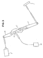
- Fig. 3 shows a second embodiment of the present invention that is like that shown in Figs. 1 and 2, except that an assist lever and a brake lever are provided.
- 1′ denotes a manipulation lever, 2′ an actuator, 3′ a balance lever, 12′ a relative displacement detecting switch, 27 a brake lever, 28 an assist lever, and 29 a parking brake.
- Figs. 4 through 7 show a third embodiment of the present invention.
- 31 denotes a brake pedal and 32 denotes a brake detecting switch for detecting the manipulation of the brake pedal 31.
- the brake detecting switch 32 inputs its detection signal to a control circuit or control means 33.
- 34 denotes an accelerator pedal and 35 denotes an accelerator detecting switch for detecting the manipulation of the accelerator pedal 34.
- the detection signal of the accelerator detecting switch 35 is inputted to the control circuit 33.
- a battery charger 38 supplies an electric power to the control circuit 33.
- a manipulation lever denoted by 39 applies a parking brake force to a brake unit (not shown) of rear wheels 40A and 40B.
- An actuator denoted by 41 is controlled by the control circuit 33 and has a speed reducer 42 and an electric motor 43. The actuator 41 assists the manipulation lever 39 and also applies the parking brake force to the brake unit by the manipulation of the manipulation switches 36 and 37.
- the manipulated force of the manipulation lever 39 acts on one end of a balance lever 44, and the operating force of the actuator 41 acts on the other end of the balance lever 44.
- the aforesaid parking brake force acts on the intermediate portion of the balance lever 44.
- the balance lever 44 is connected through a coupling mechanism 45 with an equalizer 46.
- the coupling mechanism 45 includes a first coupling member 47 disposed adjacent the balance member 44, a second coupling member 48 disposed adjacent the equalizer 46, a cylindrical member 49 fixed to the first coupling member 47 so as to define a very small interstice between the cylindrical member 49 and a large diameter portion 48A of the second coupling member 48, a spring 50 interposed between the cylindrical member 49 and the large diameter portion 48A of the second coupling member 48, a brake force detecting switch or brake detecting means 51 engaged by the cylindrical member 49 and for detecting a brake force of the degree of creep prevention, and a relative position displacement detecting switches or relative position displacement detecting means 52 and 53 for detecting the relative position displacement between the manipulation lever 39 and the actuator 41.
- the brake force detecting switch 51 detects the brake force by the movement of the cylindrical member 49 caused by the movement of the first coupling member 47.
- the relative position displacement detecting switch 52 detects the relative position displacement between the manipulation lever 39 and the actuator 41 by the tilt of the balance lever 44 caused by the manipulation of the manipulation lever 39, while the other relative position displacement detecting switch 53 detects the relative position displacement between the manipulation lever 39 and the actuator 41 by the tilt of the balance lever 44 caused by the operating force of the actuator 41.
- Each output of the relative position displacement detecting switches 52, 53 and the brake force detecting switch 51 is inputted to the control circuit 33, which controls the actuator 41 on the basis of each output of the relative position displacement detecting switches 52, 53, brake force detecting switch 51, manipulation switches 36, 37, accelerator detecting switch 35 and brake detecting switch 32.
- a bracket member denoted by 54 is adapted to fix the sheath of cables to the vehicle body.
- a normally open contact of an ignition relay is designated by 61, a manipulation switch for operation by 36, a brake detecting switch by 32, a brake force detecting switch by 51 and a first relay for creep prevention by 62.
- 63, 64 and 65 are normally open contacts of the first relay 62, the contact 63 being adapted for self holding the first relay 62, the contact 64 being adapted for actuating a second relay 66 for holding a creep prevention state, and the contact 65 being adapted for actuating a third relay 67 for an electric motor.
- 37 is a manipulation switch for release, 35 an accelerator detecting switch, 68 a normally open contact of the second relay 66, and 69 a normally closed contact of the second rely 66.
- 72 is a fourth relay for an electric motor and 73 a normally open contact 73 of the fourth relay 72, and 74 a normally closed contact of the fourth relay 72.
- An electric motor denoted by 43 constitutes the actuator 41, and a resistance 75 is provided between the battery charger 38 and the normally open contact 73 of the fourth relay 72.
- the electric motor 43 rotates in the positive direction, when the normally open contact 70 is closed and the normally closed contact 71 is opened by the operation of the third relay 67, and rotates in the reverse direction, when the normally open contact 73 is closed and the normally closed contact 74 is opened by the operation of the fourth relay 72.
- the balance lever 34 will be tilted and therefore the relative position displacement detecting switch 52 is closed and the third relay 67 is turned on.
- the electric motor 43 rotates in the positive direction and assists the manipulated force of the manipulation lever 39. Because of the positive rotation of the electric motor 43, the balance lever 34 becomes balanced. This causes the relative position displacement detecting switch 52 to be opened and also the third relay 57 to be turned off. As a result, the electric motor 43 is stopped. In this manner, the parking brake can be operated by both the manipulation lever 39 and the electric motor 43.
- the first relay 62 will be turned on. This causes the normally closed contacts 63, 64 and 65 to be closed, and the first relay 62 is self held and the third relay 67 is turned on. Also, the second relay 66 is turned on, the normally open contact 68 is closed and self held, and the normally closed contact 69 is opened.
- the electric motor 43 rotates in the positive direction.
- the balance lever 44 is tilted, the relative position displacement detecting switch 53 is closed, and since, on the other hand, the brake force detecting switch 51 is opened, the first relay 52 is turned off and the third relay 67 is also turned off.
- the electric motor 43 is consequently stopped.
- the parking brake can be operated by the manipulation of the manipulation switch 36.
- the second relay 66 will be turned off and the normally closed contact 69 that has been opened is closed. Also, since the relative position displacement detecting switch 53 has been closed, the fourth relay 72 is turned on. When the electric motor 43 is rotated in the reverse direction by the operation of the fourth relay 62 and thus the balance lever 44 becomes balanced, the relative position displacement detecting switch 53 is opened, the fourth relay 72 is turned off and therefore the electric motor 43 is stopped. Thus, the parking brake can be released by the manipulation switch 37 for release. It is noted that, if the accelerator pedal 34 is pressed down, the accelerator detecting switch 35 will be opened, and thus the parking brake can be automatically released.
- the parking brake can be operated and released by both the manipulation of the manipulation lever and manipulation switch, and the present invention becomes unexpensive since it employs the common actuator. Also, in the case of the manipulation switch, the parking brake can be automatically released by the manipulation of the accelerator pedal.
Landscapes
- Engineering & Computer Science (AREA)
- Transportation (AREA)
- Mechanical Engineering (AREA)
- Chemical & Material Sciences (AREA)
- Combustion & Propulsion (AREA)
- Automation & Control Theory (AREA)
- Braking Systems And Boosters (AREA)
- Braking Elements And Transmission Devices (AREA)
Claims (6)
- Dispositif de freinage de stationnement comprenant :
un levier de manipulation (1) et un actionneur (2) ;
ledit appareil étant caractérisé en ce qu'il comprend en outre :
un levier d'équilibrage (3) connecté à l'une de ses extrémités audit levier de manipulation (1) par l'intermédiaire d'un premier organe de couplage (4) de telle façon qu'une force d'actionnement dudit levier de manipulation (1) agit sur ladite extrémité dudit levier d'équilibrage (3), ledit levier d'équilibrage (3) étant connecté à son autre extrémité audit actionneur (2) par l'intermédiaire d'un second organe de couplage (5) de telle sorte qu'une force de commande dudit actionneur (2) agit sur ladite autre extrémité dudit levier d'équilibrage (3), ledit levier d'équilibrage (3) ayant une portion sur laquelle agit une force résultante de ladite force d'actionnement et de ladite force de commande et qui est connectée mécaniquement à des unités de freinage de roues (9, 10) de telle sorte que ladite force résultante est transmise auxdites unités de freinage (9, 10) ;
des moyens de détection de déplacement relatif (12, 13) pour détecter un déplacement relatif entre ledit premier organe de couplage (4) dudit levier de manipulation (1) et ledit second organe de couplage (5) dudit actionneur (2) ; et
un moyen de commande (14) pour commander ledit actionneur (2) de façon à réduire ledit déplacement relatif détecté par lesdits moyens de détection de déplacement relatif (12, 13). - Dispositif de freinage de stationnement selon la revendication 1, qui comprend en outre un moyen de butée (11) qui est prévu à proximité dudit levier d'équilibrage (3) et adapté pour réguler ledit levier d'équilibrage (3) de telle sorte que ledit déplacement relatif soit maintenu au-dessous d'une valeur déterminée.
- Dispositif de freinage de stationnement selon la revendication 1, dans lequel lesdits premier et second organes de couplage (4, 5) glissent librement par rapport audit levier d'équilibrage (3) de telle sorte que ledit levier d'équilibrage (3) peut être déplacé lorsque seulement l'un dudit levier de manipulation (1) ou dudit actionneur (2) est actionné.
- Dispositif de freinage de stationnement selon la revendication 1, dans lequel seulement l'un desdits premier et second organes de couplage (4, 5) glisse librement par rapport audit levier d'équilibrage (3) de telle sorte que ledit levier d'équilibrage (3) peut être déplacé lorsque seulement l'un dudit levier de manipulation (1) ou dudit actionneur (2) est actionné.
- Dispositif de freinage de stationnement qui est actionné par la manipulation d'un levier de manipulation de frein de stationnement (39) et dans lequel un actionneur (41) est prévu pour réduire la force d'actionnement dudit levier de manipulation de frein de stationnement (39), ledit dispositif de freinage de stationnement étant caractérisé par :
des moyens commutateurs de manipulation (36, 37) pour actionner et relâcher ledit actionneur (41) sans manipuler ledit levier de manipulation (39) ;
un moyen de commande pour commander le fonctionnement et le relâchement d'un freinage de stationnement produit par ledit actionneur (41) en fonction d'une sortie desdits moyens commutateurs de manipulation (36, 37) ;
ledit moyen de commande comprenant un levier d'équilibrage (44) ayant une extrémité sur laquelle agit la force d'actionnement dudit levier de manipulation (39) par l'intermédiaire d'un premier organe de couplage, une autre extrémité sur laquelle agit la force de commande dudit actionneur (41) par l'intermédiaire d'un second organe de couplage, et une portion intermédiaire sur laquelle agit une force de freinage dudit freinage de stationnement ; des moyens de détection de déplacement en position relative (52, 53) pour détecter un déplacement relatif entre ledit premier organe de couplage et ledit second organe de couplage ; un commutateur de détection de force de freinage (51) pour détecter la force de freinage transmise audit frein de stationnement ; et une pièce de commande (33) pour commander ledit actionneur (41) en fonction de ladite sortie desdits moyens commutateurs de manipulation (36, 37), en fonction d'une sortie desdits moyens de détection de déplacement de position relative (52, 53) et en fonction d'une sortie dudit commutateur de détection de force de freinage (51). - Dispositif de freinage de stationnement selon la revendication 5, dans lequel ledit moyen de commande comprend en outre un moyen de détection d'actionnement de frein (32) pour détecter une intensité d'actionnement d'une pédale de frein (31), et un moyen de détection d'actionnement d'accélérateur (35) pour détecter une intensité d'actionnement d'une pédale d'accélérateur (34), de telle sorte que lorsqu'on actionne ledit moyen commutateur de manipulation (36, 37) alors qu'une sortie de détection dudit moyen de détection d'actionnement de frein (32) est présente, ledit frein de stationnement est commandé par ledit actionneur (41), et de telle sorte que lorsqu'une sortie de détection dudit actionnement d'accélérateur est obtenue après le fonctionnement dudit frein de stationnement, ledit frein de stationnement est relâché par ledit actionneur (41).
Applications Claiming Priority (4)
| Application Number | Priority Date | Filing Date | Title |
|---|---|---|---|
| JP92744/88 | 1988-07-13 | ||
| JP1988092743U JPH0645404Y2 (ja) | 1988-07-13 | 1988-07-13 | パーキングブレーキ装置 |
| JP9274488U JPH062848Y2 (ja) | 1988-07-13 | 1988-07-13 | パーキングブレーキ装置 |
| JP92743/88 | 1988-07-13 |
Publications (2)
| Publication Number | Publication Date |
|---|---|
| EP0353876A1 EP0353876A1 (fr) | 1990-02-07 |
| EP0353876B1 true EP0353876B1 (fr) | 1992-12-16 |
Family
ID=26434121
Family Applications (1)
| Application Number | Title | Priority Date | Filing Date |
|---|---|---|---|
| EP89306936A Expired - Lifetime EP0353876B1 (fr) | 1988-07-13 | 1989-07-07 | Dispositif de freinage de stationnement |
Country Status (3)
| Country | Link |
|---|---|
| US (1) | US4991699A (fr) |
| EP (1) | EP0353876B1 (fr) |
| DE (1) | DE68903901T2 (fr) |
Families Citing this family (13)
| Publication number | Priority date | Publication date | Assignee | Title |
|---|---|---|---|---|
| FR2655005B1 (fr) * | 1989-11-27 | 1994-04-08 | Andruet Jean Claude | Dispositif de commande du frein de parc pour un vehicule automobile. |
| DE4023705A1 (de) * | 1990-07-26 | 1992-01-30 | Teves Gmbh Alfred | Anordnung zum halten eines fahrzeugs auf einer geneigten fahrbahn |
| DE4129919C2 (de) * | 1991-09-09 | 2002-05-29 | Bayerische Motoren Werke Ag | Feststellbremsanlage für Kraftwagen, insbesondere Personenkraftwagen |
| US5624352A (en) * | 1995-09-05 | 1997-04-29 | Dura Automotive Systems, Inc. | Ignition-controlled parking brake interlock |
| FR2783481B1 (fr) * | 1998-09-21 | 2000-12-15 | Renault | Frein de parking motorise comprenant une possibilite d'actionnement manuel |
| SE512909C2 (sv) * | 1998-10-01 | 2000-06-05 | Volvo Personvagnar Ab | Anordning vid manöverspak för parkeringsbromsar |
| DE10221740A1 (de) * | 2002-05-16 | 2003-12-04 | Daimler Chrysler Ag | Fahrzeugbremsanlage mit einer Betriebsbremsanlage und einer Feststellbremsanlage |
| ATE287812T1 (de) * | 2002-06-10 | 2005-02-15 | Cnh Oesterreich Gmbh | Betätigungsvorrichtung mit aktuator |
| US6848545B2 (en) * | 2002-07-31 | 2005-02-01 | Ventra Group Inc. | Brake actuation assembly for a vehicle |
| JP2006264384A (ja) * | 2005-03-22 | 2006-10-05 | Toyota Motor Corp | 電動パーキングブレーキ装置 |
| DE102006026736A1 (de) * | 2006-06-08 | 2007-12-13 | Siemens Ag | Verfahren und Steueranordnung zum gesteuerten Lösen zumindest einer elektrischen Parkbremse eines Fahrzeuges |
| FR2918452B1 (fr) * | 2007-07-02 | 2009-10-16 | Peugeot Citroen Automobiles Sa | Procede de reglage d'un frein secondaire |
| CN102328648B (zh) * | 2011-07-29 | 2013-10-16 | 中国人民解放军总后勤部军事交通运输研究所 | 液压与机械制动形式结合的挂车制动系统 |
Family Cites Families (15)
| Publication number | Priority date | Publication date | Assignee | Title |
|---|---|---|---|---|
| US1917488A (en) * | 1928-05-12 | 1933-07-11 | Bethenod Joseph | Electric servo-motor for automobiles or the like |
| US1954801A (en) * | 1929-08-26 | 1934-04-17 | Bucyrus Erie Co | Brake |
| US1998918A (en) * | 1930-01-16 | 1935-04-23 | Bendix Brake Co | Brake control mechanism |
| GB439923A (en) * | 1934-06-07 | 1935-12-09 | Geoffrey Robert Greenbergh Gat | Improvements in servo brake mechanism for vehicles and the like |
| US2724282A (en) * | 1953-02-12 | 1955-11-22 | Siemens Ag | Reversible torque amplifier with take-off shaft |
| US2763990A (en) * | 1955-03-14 | 1956-09-25 | Mercier Jean | Follow-up system |
| US2922400A (en) * | 1956-04-13 | 1960-01-26 | Hughes Tool Co | Hydraulic servomechanism with feedback-energy-dissipating control valve |
| US2910156A (en) * | 1958-01-22 | 1959-10-27 | Joseph Martin | Power operated emergency brake |
| US3270840A (en) * | 1964-08-12 | 1966-09-06 | Gen Motors Corp | Power operated parking brake having an automatic transmission control gear shift release |
| US4077487A (en) * | 1976-04-12 | 1978-03-07 | The Raymond Lee Organization, Inc. | Vehicle auxiliary braking system |
| DE2758644A1 (de) * | 1977-12-29 | 1979-07-05 | Rau Swf Autozubehoer | Einrichtung zum abbremsen von kraftfahrzeugen mit einem bremspedal |
| DE3210402A1 (de) * | 1982-03-22 | 1983-09-22 | SWF-Spezialfabrik für Autozubehör Gustav Rau GmbH, 7120 Bietigheim-Bissingen | Bremsanlage, insbesondere fuer kraftfahrzeuge |
| US4629043A (en) * | 1983-01-31 | 1986-12-16 | Mazda Motor Corporation | Electric parking brake system for a vehicle |
| US4561527A (en) * | 1983-01-31 | 1985-12-31 | Mazda Motor Corporation | Electric parking brake system for a vehicle |
| DE3704018A1 (de) * | 1987-02-10 | 1988-08-18 | Porsche Ag | Bremsvorrichtung |
-
1989
- 1989-07-06 US US07/376,031 patent/US4991699A/en not_active Expired - Fee Related
- 1989-07-07 DE DE8989306936T patent/DE68903901T2/de not_active Expired - Fee Related
- 1989-07-07 EP EP89306936A patent/EP0353876B1/fr not_active Expired - Lifetime
Also Published As
| Publication number | Publication date |
|---|---|
| DE68903901T2 (de) | 1993-07-15 |
| US4991699A (en) | 1991-02-12 |
| DE68903901D1 (de) | 1993-01-28 |
| EP0353876A1 (fr) | 1990-02-07 |
Similar Documents
| Publication | Publication Date | Title |
|---|---|---|
| EP0353876B1 (fr) | Dispositif de freinage de stationnement | |
| US5178237A (en) | Power-assisted parking brake for vehicles | |
| US6704637B1 (en) | Speed control for a work vehicle | |
| US20040251071A1 (en) | Automatic electric power parking brake for a motor vehicle | |
| US6280004B1 (en) | Brake control system for balanced braking of a towed vehicle | |
| EP1795411B1 (fr) | Frein de stationnement électrique | |
| JPS62265424A (ja) | 被動部材制御装置 | |
| JP2720978B2 (ja) | 自動車の操縦方法及びその装置 | |
| US6079794A (en) | Brake-actuating device | |
| JPH0645404Y2 (ja) | パーキングブレーキ装置 | |
| JP2001097069A (ja) | 運転補助装置 | |
| JP3693800B2 (ja) | コラムシフト装置 | |
| EP0405550A3 (fr) | Dispositif de commande de transmission pour véhicule automobile | |
| JP3934824B2 (ja) | 車両用ブレーキ装置 | |
| JPH062848Y2 (ja) | パーキングブレーキ装置 | |
| JP2648345B2 (ja) | パーキングブレーキ装置 | |
| JP2502838Y2 (ja) | パ―キングブレ―キ装置 | |
| KR0113825Y1 (ko) | 변속기 이용의 자동 주차브레이크장치 | |
| KR100380612B1 (ko) | 버튼식 자동 파킹장치 | |
| KR100214716B1 (ko) | 자동차의 운행 제어시스템 | |
| KR100204779B1 (ko) | 4륜구동차의 구동 제어장치 | |
| JPH02248762A (ja) | 車両のギヤコントロール装置 | |
| JPS6347540Y2 (fr) | ||
| JPH02151552A (ja) | パーキングブレーキ装置 | |
| JPS59102648A (ja) | パ−キングブレ−キ自動解除装置 |
Legal Events
| Date | Code | Title | Description |
|---|---|---|---|
| PUAI | Public reference made under article 153(3) epc to a published international application that has entered the european phase |
Free format text: ORIGINAL CODE: 0009012 |
|
| AK | Designated contracting states |
Kind code of ref document: A1 Designated state(s): DE |
|
| 17P | Request for examination filed |
Effective date: 19900405 |
|
| 17Q | First examination report despatched |
Effective date: 19910507 |
|
| GRAA | (expected) grant |
Free format text: ORIGINAL CODE: 0009210 |
|
| AK | Designated contracting states |
Kind code of ref document: B1 Designated state(s): DE |
|
| REF | Corresponds to: |
Ref document number: 68903901 Country of ref document: DE Date of ref document: 19930128 |
|
| PLBE | No opposition filed within time limit |
Free format text: ORIGINAL CODE: 0009261 |
|
| STAA | Information on the status of an ep patent application or granted ep patent |
Free format text: STATUS: NO OPPOSITION FILED WITHIN TIME LIMIT |
|
| 26N | No opposition filed | ||
| PGFP | Annual fee paid to national office [announced via postgrant information from national office to epo] |
Ref country code: DE Payment date: 19991026 Year of fee payment: 11 |
|
| PG25 | Lapsed in a contracting state [announced via postgrant information from national office to epo] |
Ref country code: DE Free format text: LAPSE BECAUSE OF NON-PAYMENT OF DUE FEES Effective date: 20010501 |